EP1544355B1 - Barrière pour véhicules - Google Patents
Barrière pour véhicules Download PDFInfo
- Publication number
- EP1544355B1 EP1544355B1 EP04029527A EP04029527A EP1544355B1 EP 1544355 B1 EP1544355 B1 EP 1544355B1 EP 04029527 A EP04029527 A EP 04029527A EP 04029527 A EP04029527 A EP 04029527A EP 1544355 B1 EP1544355 B1 EP 1544355B1
- Authority
- EP
- European Patent Office
- Prior art keywords
- barrier
- arm
- boom
- barrier assembly
- spring
- Prior art date
- Legal status (The legal status is an assumption and is not a legal conclusion. Google has not performed a legal analysis and makes no representation as to the accuracy of the status listed.)
- Expired - Lifetime
Links
Images
Classifications
-
- E—FIXED CONSTRUCTIONS
- E01—CONSTRUCTION OF ROADS, RAILWAYS, OR BRIDGES
- E01F—ADDITIONAL WORK, SUCH AS EQUIPPING ROADS OR THE CONSTRUCTION OF PLATFORMS, HELICOPTER LANDING STAGES, SIGNS, SNOW FENCES, OR THE LIKE
- E01F13/00—Arrangements for obstructing or restricting traffic, e.g. gates, barricades ; Preventing passage of vehicles of selected category or dimensions
- E01F13/04—Arrangements for obstructing or restricting traffic, e.g. gates, barricades ; Preventing passage of vehicles of selected category or dimensions movable to allow or prevent passage
- E01F13/06—Arrangements for obstructing or restricting traffic, e.g. gates, barricades ; Preventing passage of vehicles of selected category or dimensions movable to allow or prevent passage by swinging into open position about a vertical or horizontal axis parallel to the road direction, i.e. swinging gates
Definitions
- the invention relates to a barrier with a cabinet column and a drive for pivoting the barrier boom about a horizontal axis between the locking and the open position and a pivot joint with a vertical axis about which the barrier boom upon violent opening is pivotally, according to the preamble of Claim 1.
- Such barriers are mainly used as vehicle barriers, especially as parking barriers to control the entrance and exit of parking areas.
- parking barriers in the barrier boom have a predetermined breaking point.
- the object of the invention is to design a conventional barrier with the least possible changes so that its function is not impaired if it is forcibly opened by a vehicle or otherwise.
- the barrier is designed in such a way that, when the barrier boom is in the blocking position and is locked by a vehicle or otherwise, e.g. is forcibly opened by a person, automatically, for example, by a corresponding drive back to its locked position.
- the barrier boom is not destroyed during the violent opening. This prevents that after a violent opening of the barrier, the coming vehicles can pass the barrier without authorization.
- the barrier according to the invention can also be opened if, for example, the drive for opening the barrier can not be actuated. Lock position is to be understood not only the position in which the barrier boom is completely closed, but any position in which the passage of a vehicle is prevented.
- a pivot joint is provided, around which the barrier boom during violent opening and when moving back into the locked position is pivoted.
- the pivot joint may be provided on the barrier boom, preferably adjacent to the pivot axis of the barrier boom, about which it is pivotable on the barrier pillar for opening and closing the barrier.
- the swivel joint can also be located on the cabinet pillar.
- the pivot joint normally has a vertical pivot axis, so that when a vehicle is against the Barrier moves, he can dodge to the side.
- the pivot joint is preferably designed so that the barrier boom can move laterally both in the direction of travel as in the opposite direction. This prevents, for example, that a vehicle that has passed the exit barrier properly when returning, for example, rolling back from an exit ramp to the exit barrier, ie in the opposite direction, destroys the closed barrier tree.
- a further pivot joint may be provided, which has a horizontal pivot axis, so that the barrier boom can also move up and / or down. This can prevent a person from attempting to destroy the barrier boom by forcibly pressing them up and / or down so that he can not return to the blocking position.
- the barrier according to the invention is preferably designed such that the barrier boom is designed so as to be able to be deflected sideways and upwards for protection against forced opening.
- a predetermined force In order to forcibly open the barrier according to the invention with the barrier boom in the blocking position, a predetermined force must be overcome.
- This force can be specified by appropriate regulations.
- a conventional barrier boom with predetermined breaking points according to relevant standards should break if a force of 20 kg acts on it. Accordingly, in the barrier according to the invention, the barrier boom is moved out of its locked position only when a force of e.g. 10 to 50 kg acts.
- the pivot joint for forcibly opening the barrier boom and for moving back into the blocking position can be formed, for example, by the fact that the barrier column, on the the barrier boom is pivotally mounted for opening and closing, consists of two parts rotatable relative to each other, wherein the barrier boom is hinged to open and close the barrier to one part pivotally, while the other part forms the foot with which the cabinet column at the bottom supported and fixed to the ground.
- the part to which the boom is hinged to open and close the barrier can be formed by the barrier column of a conventional, commercially available barrier.
- the barrier column of the conventional barrier only needs to be rotatable relative to the other part, which forms the foot of the barrier according to the invention, so as to be rotatable about a vertical axis extending in the direction of the barrier column.
- a conventional barrier with motor and gear in the rack column can be used virtually without any change to the construction of the barrier according to the invention.
- the barrier pillar of the conventional barrier can be arranged as an inner part in an outer part with a corresponding inner recess, for example a tube, and e.g. be rotatably mounted with a rolling element bearing relative to the outer part.
- a spring may be provided, which is arranged for example in the inner part, ie the pillar pillar of the conventional barrier, and outwards against, for example, by a ball, roller or the same rolling elements formed locking member presses, which in a receptacle in engages the outer part forming the foot.
- the force to be overcome during the violent opening of the barrier boom is then formed by the force that is necessary for the spring-loaded locking member to disengage, that is to say it is moved out of the receptacle.
- the barrier according to the invention can be abused if, for example, a person deliberately opens the barrier by force, that is to say by overcoming said predetermined force.
- the possibility of abuse is not greater than in the known barrier with predetermined breaking point, of course, without the barrier according to the invention in abuse case does not have the initially described disadvantages of the known barrier.
- the abuse in the barrier according to the invention can be counteracted in the same way as in the conventional barrier, e.g. through a video surveillance or the like.
- a device for detecting a vehicle is preferably provided in the movement area of the barrier boom, with which a person may also be detected can.
- This device may comprise video image processing or a light barrier, an ultrasonic sensor, an induction loop or the like.
- a time measuring device may be provided to move back the barrier boom after a predetermined period of time after the violent opening. This period of time can be adjustable. The time measuring device can, for example, by a Kontrollund Safety device, such as an image processing device are triggered.
- the barrier boom of the barrier according to the invention may be formed as a rigid tube.
- the barrier according to the invention may be a kink barrier, that is to say comprise a barrier boom with at least one joint pivotable about a horizontal axis, as used, for example, in low-altitude parking spaces. Furthermore, it is advantageous to make the barrier tree illuminated.
- a drive may be provided for automatic retraction of the barrier boom in the locked position after the violent opening.
- a drive may be provided.
- the drive to move back the barrier boom in the locked position after violent opening of the barrier may be formed by a material with memory effect, which resumes its original shape after deformation.
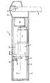
- the single figure shows a barrier with longitudinally cut cabinet column and partially illustrated barrier boom.
- the barrier has a barrier column 1, which consists of two parts, namely an inner part 2 and an outer tube forming an outer tube 3, which are opposite one another around a vertical axis S are rotatably mounted, which also forms the longitudinal axis of the cabinet column 1.
- the inner part 2 has an inner tube 4 as a housing.
- a radial bearing with rolling elements 5 is provided, which roll on a race 6 on the inner wall of the outer tube 3.
- the outer tube 3 forms the foot, with which the cabinet column 1 is supported on the ground and fixed to the ground.
- the inner part 2 is formed by the barrier column of a conventional barrier. That is, the inner tube 4, the housing of the barrier pillar of the conventional barrier, wherein in the inner tube 4 or housing the motor 7 and the gear 8 are arranged for driving the barrier boom 9 to him about a horizontal axis between the illustrated position, in the barrier boom 9 is pivoted downwards, and the open position in which the barrier boom 9 is pivoted upwards to pivot.
- the barrier boom 9 is attached to a arranged on the head 12 of the inner part 2 shaft 11, which is driven by the motor 7 via the gear 8 to pivot the barrier boom 9 about the horizontal axis H.
- the barrier boom 9 Due to the rotatable mounting of the inner tube 4 in the outer tube 3 about the vertical axis S of the barrier boom 9 from the locking position shown in the drawing to the side, ie pivoted in the direction of travel from the road when a vehicle drives up on him.
- the barrier boom 9 is pivoted in the locked position only when driving a vehicle or in another violent action to the side, a device for generating a predetermined force is provided, which must be overcome during the violent opening of the closed barrier boom 9.
- a radially displaceable, with a spring 13 outwardly loaded e.g. formed as a rolling element formed member 14 which engages in a (not shown) recess in the raceway 6 on the outer tube 3.
- a spring 13 outwardly loaded, e.g. formed as a rolling element formed member 14 which engages in a (not shown) recess in the raceway 6 on the outer tube 3.
- a motor 15 is provided in the inner tube 4, on the motor shaft 16, a gear 17 is seated, which meshes with a ring gear 18 which meshes with the Inside the outer tube 3 is fixed.
Landscapes
- Engineering & Computer Science (AREA)
- Architecture (AREA)
- Civil Engineering (AREA)
- Structural Engineering (AREA)
- Refuge Islands, Traffic Blockers, Or Guard Fence (AREA)
- Vehicle Interior And Exterior Ornaments, Soundproofing, And Insulation (AREA)
- Glass Compositions (AREA)
- Automatic Cycles, And Cycles In General (AREA)
Claims (8)
- Barrière avec un montant de barrière (1) et un entraînement (7) pour faire pivoter la lisse de barrière (9) autour d'un axe horizontal (H) entre la position de barrage et la position d'ouverture, une articulation pivotante avec un axe vertical (S), autour duquel la lisse de barrière (9) peut pivoter en cas d'ouverture en force, un dispositif pour produire une force prédéterminée à surmonter lors de l'ouverture en force de la lisse de barrière (9) et un entraînement pour ramener automatiquement la lisse de barrière (9) basculée en force dans sa position initiale, caractérisée en ce que pour former l'articulation pivotante, le montant de barrière (1) se compose d'au moins deux parties (2, 3) pouvant tourner l'une par rapport à l'autre autour de l'axe vertical (S), la lisse de barrière (9) étant articulée de manière pivotante pour ouvrir et fermer la barrière sur une partie (2) et l'autre partie (3) formant le pied d'appui et de fixation du montant de barrière (1).
- Barrière selon la revendication 1, caractérisée en ce que les deux parties pouvant tourner l'une par rapport à l'autre (2, 3) sont formées de deux tubes de diamètre différent emmanchés l'un dans l'autre.
- Barrière selon la revendication 1 ou 2, caractérisée en ce que l'entraînement (7) pour l'actionnement de la lisse de barrière (9) est fixé sur la partie (2) sur laquelle la lisse de barrière (9) est articulée de manière pivotante.
- Barrière selon la revendication 2 et 3, caractérisée en ce que la partie (2) sur laquelle la lisse de barrière (9) est articulée de façon pivotante est le tube intérieur.
- Barrière selon la revendication 1, caractérisée en ce que l'entraînement pour ramener automatiquement la lisse de barrière (9) ouverte en force dans sa position initiale est formé par un ressort, un moteur et/ou un dispositif pneumatique ou hydraulique.
- Barrière selon la revendication 1, caractérisée en ce que le dispositif pour produire une force prédéterminée à vaincre en cas d'ouverture forcée de la lisse de barrière (9) est formé par un ressort (13).
- Barrière selon la revendication 6, caractérisée en ce que le ressort (13) contraint un organe de verrouillage (14) disposé dans une partie (2) en direction de l'autre partie, qui est dotée d'un logement pour l'organe de verrouillage (14).
- Barrière selon l'une des revendications précédentes, caractérisée en ce qu'afin d'empêcher le retour de la lisse de barrière (9) ouverte en force si un véhicule ou une personne se trouve dans la zone de mouvement de la lisse de barrière (9), il est prévu un dispositif pour la détection des véhicules et/ou des personnes.
Applications Claiming Priority (2)
| Application Number | Priority Date | Filing Date | Title |
|---|---|---|---|
| DE10359383 | 2003-12-18 | ||
| DE10359383A DE10359383A1 (de) | 2003-12-18 | 2003-12-18 | Fahrzeugschranke |
Publications (2)
| Publication Number | Publication Date |
|---|---|
| EP1544355A1 EP1544355A1 (fr) | 2005-06-22 |
| EP1544355B1 true EP1544355B1 (fr) | 2008-12-03 |
Family
ID=34485457
Family Applications (1)
| Application Number | Title | Priority Date | Filing Date |
|---|---|---|---|
| EP04029527A Expired - Lifetime EP1544355B1 (fr) | 2003-12-18 | 2004-12-14 | Barrière pour véhicules |
Country Status (4)
| Country | Link |
|---|---|
| US (1) | US7263803B2 (fr) |
| EP (1) | EP1544355B1 (fr) |
| AT (1) | ATE416276T1 (fr) |
| DE (2) | DE10359383A1 (fr) |
Cited By (1)
| Publication number | Priority date | Publication date | Assignee | Title |
|---|---|---|---|---|
| DE102020109086A1 (de) | 2020-04-01 | 2021-10-07 | ELKA Torantriebe GmbH u. Co. Betriebs KG | Schrankenbaum zur Montage an einer Schrankensäule einer Schranke sowie Schranke mit einem an einer Schrankensäule montierten Schrankenbaum |
Families Citing this family (10)
| Publication number | Priority date | Publication date | Assignee | Title |
|---|---|---|---|---|
| US7775738B2 (en) | 2004-10-22 | 2010-08-17 | Darcy Daniel T | Vehicle barrier system |
| US20060090408A1 (en) * | 2004-10-22 | 2006-05-04 | Darcy Daniel T | Vehicle barrier system |
| US7818920B2 (en) * | 2007-11-06 | 2010-10-26 | Causey Lynn R | Barrier gate with torque limiter |
| US8983677B2 (en) * | 2008-10-01 | 2015-03-17 | Honeywell International Inc. | Acoustic fingerprinting of mechanical devices |
| US20100082180A1 (en) * | 2008-10-01 | 2010-04-01 | Honeywell International Inc. | Errant vehicle countermeasures |
| EA015905B1 (ru) * | 2009-08-19 | 2011-12-30 | Николай Викторович СУХАЧЕВ | Комбинированное устройство для ограничения проезда транспортных средств |
| DE102009054224A1 (de) * | 2009-11-21 | 2011-05-26 | AR&T, Applied Robot & Technologies UG (haftungsbeschränkt) | Ein automatisches ein- und ausfahrbares Pfostensystem |
| US8618906B2 (en) * | 2010-08-18 | 2013-12-31 | Ahmed I.S.I. Al-Jafar | Remote control parking barrier |
| GB2523405B (en) * | 2014-02-25 | 2018-02-21 | Newgate (Newark) Ltd | A barrier with an actuation system and manual actuation means mounted on a removably insertable common support frame |
| DE202014004389U1 (de) | 2014-05-24 | 2014-06-23 | Magnetic Autocontrol Gmbh | Schrankenbaum |
Family Cites Families (15)
| Publication number | Priority date | Publication date | Assignee | Title |
|---|---|---|---|---|
| DE1907056U (de) * | 1964-07-31 | 1964-12-23 | Speiser G M B H Bau Und Indust | Absperrvorrichtung fuer parkplaetze, einfahrten od. dgl. |
| DE1755548A1 (de) * | 1968-05-21 | 1971-09-30 | Railroad Accessories Corp | Verkehrsregelungsvorrichtung |
| DE3015284C2 (de) * | 1980-04-21 | 1984-02-02 | Norbert 2056 Glinde Kille | Antriebsmechanismus für eine Schranke |
| US4364200A (en) * | 1980-12-29 | 1982-12-21 | Kettering Medical Center | Automatically operable automotive vehicle gate apparatus provided with self protection and automotive protection |
| US4844653A (en) * | 1987-06-23 | 1989-07-04 | Dickinson Harry D | Cable-beam trafficway barrier |
| DE9212297U1 (de) * | 1992-09-11 | 1992-12-17 | Reinhold, Günter, 8035 Gauting | Parkplatzsicherung für PKW-Stellplätze |
| AT402311B (de) | 1995-03-20 | 1997-04-25 | Skidata Gmbh | Absperreinrichtung |
| FR2768447B1 (fr) * | 1997-09-18 | 1999-12-03 | Auxiliaire De Construction D O | Portique pour la limitation de la hauteur d'un passage |
| US6370821B1 (en) * | 1999-05-27 | 2002-04-16 | Mccord David W. | Flexible gate |
| US6470626B2 (en) * | 2001-01-17 | 2002-10-29 | Mtr, Inc. | Gate release mechanism with detent and plunger, and gate incorporating same |
| US6618993B2 (en) * | 2001-03-19 | 2003-09-16 | Thomas J. Burke | Railroad grade crossing assembly |
| US20020152682A1 (en) * | 2001-04-24 | 2002-10-24 | Walter Parsadayan | Method and apparatus for breakaway mounting of security gate to drive mechanism |
| US7062879B2 (en) * | 2001-08-08 | 2006-06-20 | Federal Apd, Inc. | Security gate |
| WO2003027398A1 (fr) * | 2001-09-21 | 2003-04-03 | Prospective Concepts Ag | Barriere pneumatique |
| US6997417B2 (en) * | 2003-12-31 | 2006-02-14 | Nicholas Zarkades | Apparatus for controlling traffic flow along a pathway |
-
2003
- 2003-12-18 DE DE10359383A patent/DE10359383A1/de not_active Withdrawn
-
2004
- 2004-12-14 DE DE502004008578T patent/DE502004008578D1/de not_active Expired - Lifetime
- 2004-12-14 AT AT04029527T patent/ATE416276T1/de active
- 2004-12-14 EP EP04029527A patent/EP1544355B1/fr not_active Expired - Lifetime
- 2004-12-16 US US11/014,634 patent/US7263803B2/en not_active Expired - Fee Related
Cited By (1)
| Publication number | Priority date | Publication date | Assignee | Title |
|---|---|---|---|---|
| DE102020109086A1 (de) | 2020-04-01 | 2021-10-07 | ELKA Torantriebe GmbH u. Co. Betriebs KG | Schrankenbaum zur Montage an einer Schrankensäule einer Schranke sowie Schranke mit einem an einer Schrankensäule montierten Schrankenbaum |
Also Published As
| Publication number | Publication date |
|---|---|
| US7263803B2 (en) | 2007-09-04 |
| US20050150165A1 (en) | 2005-07-14 |
| DE502004008578D1 (de) | 2009-01-15 |
| ATE416276T1 (de) | 2008-12-15 |
| DE10359383A1 (de) | 2005-07-28 |
| EP1544355A1 (fr) | 2005-06-22 |
Similar Documents
| Publication | Publication Date | Title |
|---|---|---|
| DE69109897T2 (de) | Schranke für Begrenzungsbarriere. | |
| EP0309488B1 (fr) | Poteau de barriere sans points de serrage | |
| DE69000686T2 (de) | Wagenparkanlage fuer individuelles und automatisches parken im stadtbereich. | |
| DE69617251T2 (de) | Parkhaus für fahrräder | |
| EP1544355A1 (fr) | Barrière pour véhicules | |
| DE2824937A1 (de) | Vorrichtung zum reservieren einzelner parkflaechen fuer kraftfahrzeuge | |
| EP3658734B1 (fr) | Système de porte | |
| DE69101266T2 (de) | Anzeigevorrichtung. | |
| EP1447272A2 (fr) | Rampe déployable pour véhicules | |
| DE19531284A1 (de) | Schienenfahrzeug für den Personenverkehr | |
| DE2915190A1 (de) | Versperrbare gattermechanik mit selbsttaetiger neueinstellung | |
| EP4045756B1 (fr) | Agencement pour un système de passage et procédé pour faire fonctionner un agencement | |
| EP0443052B1 (fr) | Dispositif barrière pour des emplacements dans un parking | |
| EP0617188B1 (fr) | Porte pivotante pour un portillon | |
| DE29620291U1 (de) | Absperreinrichtung | |
| EP4087997B1 (fr) | Dispositif de stationnement équipé d'un ensemble de porte | |
| DE8713254U1 (de) | Klemmstellenfreier Absperrpfosten | |
| DE4314026A1 (de) | Schwenktüre für einen Personendurchgang | |
| DE19909700A1 (de) | Vorrichtung zur Erleichterung des Ein- und Aussteigens an einem Fahrzeug des öffentlichen Personenverkehrs, insbesondere einem Bahnsteige anfahrenden Fahrzeug | |
| DE29701462U1 (de) | Vorrichtung zur automatischen Steuerung von Toren oder Türen | |
| DE2503238A1 (de) | Abrollsicherung fuer elektromotorisch betaetigte rolltore | |
| DE4446403A1 (de) | Gepanzerte Schiebetür für gegen Einbruch, Beschuß, Aufbruch und unbefugten Zugang zu sichernde Räume | |
| DE1800697A1 (de) | Energieabsorbierende Fahrzeuglenkung | |
| EP1081313B1 (fr) | Station de transfert pour l'emmagasinage et le démagasinage de véhicules automobiles dans un garage à étages | |
| DE4309067A1 (de) | Schwenktüre für einen Personendurchgang |
Legal Events
| Date | Code | Title | Description |
|---|---|---|---|
| PUAI | Public reference made under article 153(3) epc to a published international application that has entered the european phase |
Free format text: ORIGINAL CODE: 0009012 |
|
| AK | Designated contracting states |
Kind code of ref document: A1 Designated state(s): AT BE BG CH CY CZ DE DK EE ES FI FR GB GR HU IE IS IT LI LT LU MC NL PL PT RO SE SI SK TR |
|
| AX | Request for extension of the european patent |
Extension state: AL BA HR LV MK YU |
|
| 17P | Request for examination filed |
Effective date: 20051122 |
|
| AKX | Designation fees paid |
Designated state(s): AT BE BG CH CY CZ DE DK EE ES FI FR GB GR HU IE IS IT LI LT LU MC NL PL PT RO SE SI SK TR |
|
| 17Q | First examination report despatched |
Effective date: 20071221 |
|
| GRAP | Despatch of communication of intention to grant a patent |
Free format text: ORIGINAL CODE: EPIDOSNIGR1 |
|
| GRAS | Grant fee paid |
Free format text: ORIGINAL CODE: EPIDOSNIGR3 |
|
| GRAA | (expected) grant |
Free format text: ORIGINAL CODE: 0009210 |
|
| AK | Designated contracting states |
Kind code of ref document: B1 Designated state(s): AT BE BG CH CY CZ DE DK EE ES FI FR GB GR HU IE IS IT LI LT LU MC NL PL PT RO SE SI SK TR |
|
| REG | Reference to a national code |
Ref country code: GB Ref legal event code: FG4D Free format text: NOT ENGLISH |
|
| REG | Reference to a national code |
Ref country code: CH Ref legal event code: EP |
|
| REG | Reference to a national code |
Ref country code: IE Ref legal event code: FG4D Free format text: LANGUAGE OF EP DOCUMENT: GERMAN |
|
| REF | Corresponds to: |
Ref document number: 502004008578 Country of ref document: DE Date of ref document: 20090115 Kind code of ref document: P |
|
| PG25 | Lapsed in a contracting state [announced via postgrant information from national office to epo] |
Ref country code: LT Free format text: LAPSE BECAUSE OF FAILURE TO SUBMIT A TRANSLATION OF THE DESCRIPTION OR TO PAY THE FEE WITHIN THE PRESCRIBED TIME-LIMIT Effective date: 20081203 Ref country code: ES Free format text: LAPSE BECAUSE OF FAILURE TO SUBMIT A TRANSLATION OF THE DESCRIPTION OR TO PAY THE FEE WITHIN THE PRESCRIBED TIME-LIMIT Effective date: 20090314 |
|
| PG25 | Lapsed in a contracting state [announced via postgrant information from national office to epo] |
Ref country code: SI Free format text: LAPSE BECAUSE OF FAILURE TO SUBMIT A TRANSLATION OF THE DESCRIPTION OR TO PAY THE FEE WITHIN THE PRESCRIBED TIME-LIMIT Effective date: 20081203 Ref country code: PL Free format text: LAPSE BECAUSE OF FAILURE TO SUBMIT A TRANSLATION OF THE DESCRIPTION OR TO PAY THE FEE WITHIN THE PRESCRIBED TIME-LIMIT Effective date: 20081203 Ref country code: FI Free format text: LAPSE BECAUSE OF FAILURE TO SUBMIT A TRANSLATION OF THE DESCRIPTION OR TO PAY THE FEE WITHIN THE PRESCRIBED TIME-LIMIT Effective date: 20081203 |
|
| REG | Reference to a national code |
Ref country code: IE Ref legal event code: FD4D |
|
| PG25 | Lapsed in a contracting state [announced via postgrant information from national office to epo] |
Ref country code: EE Free format text: LAPSE BECAUSE OF FAILURE TO SUBMIT A TRANSLATION OF THE DESCRIPTION OR TO PAY THE FEE WITHIN THE PRESCRIBED TIME-LIMIT Effective date: 20081203 Ref country code: IE Free format text: LAPSE BECAUSE OF FAILURE TO SUBMIT A TRANSLATION OF THE DESCRIPTION OR TO PAY THE FEE WITHIN THE PRESCRIBED TIME-LIMIT Effective date: 20081203 Ref country code: MC Free format text: LAPSE BECAUSE OF NON-PAYMENT OF DUE FEES Effective date: 20081231 Ref country code: BG Free format text: LAPSE BECAUSE OF FAILURE TO SUBMIT A TRANSLATION OF THE DESCRIPTION OR TO PAY THE FEE WITHIN THE PRESCRIBED TIME-LIMIT Effective date: 20090303 Ref country code: RO Free format text: LAPSE BECAUSE OF FAILURE TO SUBMIT A TRANSLATION OF THE DESCRIPTION OR TO PAY THE FEE WITHIN THE PRESCRIBED TIME-LIMIT Effective date: 20081203 |
|
| REG | Reference to a national code |
Ref country code: CH Ref legal event code: PL |
|
| PG25 | Lapsed in a contracting state [announced via postgrant information from national office to epo] |
Ref country code: CZ Free format text: LAPSE BECAUSE OF FAILURE TO SUBMIT A TRANSLATION OF THE DESCRIPTION OR TO PAY THE FEE WITHIN THE PRESCRIBED TIME-LIMIT Effective date: 20081203 Ref country code: PT Free format text: LAPSE BECAUSE OF FAILURE TO SUBMIT A TRANSLATION OF THE DESCRIPTION OR TO PAY THE FEE WITHIN THE PRESCRIBED TIME-LIMIT Effective date: 20090504 Ref country code: IS Free format text: LAPSE BECAUSE OF FAILURE TO SUBMIT A TRANSLATION OF THE DESCRIPTION OR TO PAY THE FEE WITHIN THE PRESCRIBED TIME-LIMIT Effective date: 20090403 Ref country code: SE Free format text: LAPSE BECAUSE OF FAILURE TO SUBMIT A TRANSLATION OF THE DESCRIPTION OR TO PAY THE FEE WITHIN THE PRESCRIBED TIME-LIMIT Effective date: 20090303 |
|
| PG25 | Lapsed in a contracting state [announced via postgrant information from national office to epo] |
Ref country code: SK Free format text: LAPSE BECAUSE OF FAILURE TO SUBMIT A TRANSLATION OF THE DESCRIPTION OR TO PAY THE FEE WITHIN THE PRESCRIBED TIME-LIMIT Effective date: 20081203 |
|
| PLBE | No opposition filed within time limit |
Free format text: ORIGINAL CODE: 0009261 |
|
| STAA | Information on the status of an ep patent application or granted ep patent |
Free format text: STATUS: NO OPPOSITION FILED WITHIN TIME LIMIT |
|
| PG25 | Lapsed in a contracting state [announced via postgrant information from national office to epo] |
Ref country code: DK Free format text: LAPSE BECAUSE OF FAILURE TO SUBMIT A TRANSLATION OF THE DESCRIPTION OR TO PAY THE FEE WITHIN THE PRESCRIBED TIME-LIMIT Effective date: 20081203 Ref country code: LI Free format text: LAPSE BECAUSE OF NON-PAYMENT OF DUE FEES Effective date: 20081231 Ref country code: CH Free format text: LAPSE BECAUSE OF NON-PAYMENT OF DUE FEES Effective date: 20081231 |
|
| 26N | No opposition filed |
Effective date: 20090904 |
|
| PG25 | Lapsed in a contracting state [announced via postgrant information from national office to epo] |
Ref country code: CY Free format text: LAPSE BECAUSE OF FAILURE TO SUBMIT A TRANSLATION OF THE DESCRIPTION OR TO PAY THE FEE WITHIN THE PRESCRIBED TIME-LIMIT Effective date: 20081203 Ref country code: HU Free format text: LAPSE BECAUSE OF FAILURE TO SUBMIT A TRANSLATION OF THE DESCRIPTION OR TO PAY THE FEE WITHIN THE PRESCRIBED TIME-LIMIT Effective date: 20090604 Ref country code: LU Free format text: LAPSE BECAUSE OF NON-PAYMENT OF DUE FEES Effective date: 20081214 |
|
| PG25 | Lapsed in a contracting state [announced via postgrant information from national office to epo] |
Ref country code: TR Free format text: LAPSE BECAUSE OF FAILURE TO SUBMIT A TRANSLATION OF THE DESCRIPTION OR TO PAY THE FEE WITHIN THE PRESCRIBED TIME-LIMIT Effective date: 20081203 |
|
| PG25 | Lapsed in a contracting state [announced via postgrant information from national office to epo] |
Ref country code: GR Free format text: LAPSE BECAUSE OF FAILURE TO SUBMIT A TRANSLATION OF THE DESCRIPTION OR TO PAY THE FEE WITHIN THE PRESCRIBED TIME-LIMIT Effective date: 20090304 |
|
| PG25 | Lapsed in a contracting state [announced via postgrant information from national office to epo] |
Ref country code: IT Free format text: LAPSE BECAUSE OF FAILURE TO SUBMIT A TRANSLATION OF THE DESCRIPTION OR TO PAY THE FEE WITHIN THE PRESCRIBED TIME-LIMIT Effective date: 20081203 |
|
| REG | Reference to a national code |
Ref country code: FR Ref legal event code: PLFP Year of fee payment: 12 |
|
| REG | Reference to a national code |
Ref country code: FR Ref legal event code: PLFP Year of fee payment: 13 |
|
| PGFP | Annual fee paid to national office [announced via postgrant information from national office to epo] |
Ref country code: NL Payment date: 20161221 Year of fee payment: 13 Ref country code: DE Payment date: 20161213 Year of fee payment: 13 Ref country code: GB Payment date: 20161222 Year of fee payment: 13 |
|
| PGFP | Annual fee paid to national office [announced via postgrant information from national office to epo] |
Ref country code: AT Payment date: 20161222 Year of fee payment: 13 Ref country code: FR Payment date: 20161222 Year of fee payment: 13 Ref country code: BE Payment date: 20161221 Year of fee payment: 13 |
|
| REG | Reference to a national code |
Ref country code: DE Ref legal event code: R119 Ref document number: 502004008578 Country of ref document: DE |
|
| REG | Reference to a national code |
Ref country code: NL Ref legal event code: MM Effective date: 20180101 |
|
| REG | Reference to a national code |
Ref country code: AT Ref legal event code: MM01 Ref document number: 416276 Country of ref document: AT Kind code of ref document: T Effective date: 20171214 |
|
| GBPC | Gb: european patent ceased through non-payment of renewal fee |
Effective date: 20171214 |
|
| PG25 | Lapsed in a contracting state [announced via postgrant information from national office to epo] |
Ref country code: NL Free format text: LAPSE BECAUSE OF NON-PAYMENT OF DUE FEES Effective date: 20180101 |
|
| REG | Reference to a national code |
Ref country code: FR Ref legal event code: ST Effective date: 20180831 |
|
| REG | Reference to a national code |
Ref country code: BE Ref legal event code: MM Effective date: 20171231 |
|
| PG25 | Lapsed in a contracting state [announced via postgrant information from national office to epo] |
Ref country code: DE Free format text: LAPSE BECAUSE OF NON-PAYMENT OF DUE FEES Effective date: 20180703 Ref country code: FR Free format text: LAPSE BECAUSE OF NON-PAYMENT OF DUE FEES Effective date: 20180102 |
|
| PG25 | Lapsed in a contracting state [announced via postgrant information from national office to epo] |
Ref country code: AT Free format text: LAPSE BECAUSE OF NON-PAYMENT OF DUE FEES Effective date: 20171214 Ref country code: GB Free format text: LAPSE BECAUSE OF NON-PAYMENT OF DUE FEES Effective date: 20171214 Ref country code: BE Free format text: LAPSE BECAUSE OF NON-PAYMENT OF DUE FEES Effective date: 20171231 |