EP1544392A1 - Charnière, particulièrement pour soutenir des cadres, et méthode pour atteindre au moins un de ses composants - Google Patents
Charnière, particulièrement pour soutenir des cadres, et méthode pour atteindre au moins un de ses composants Download PDFInfo
- Publication number
- EP1544392A1 EP1544392A1 EP04029974A EP04029974A EP1544392A1 EP 1544392 A1 EP1544392 A1 EP 1544392A1 EP 04029974 A EP04029974 A EP 04029974A EP 04029974 A EP04029974 A EP 04029974A EP 1544392 A1 EP1544392 A1 EP 1544392A1
- Authority
- EP
- European Patent Office
- Prior art keywords
- hinge
- cavity
- bushing
- segment
- pintle
- Prior art date
- Legal status (The legal status is an assumption and is not a legal conclusion. Google has not performed a legal analysis and makes no representation as to the accuracy of the status listed.)
- Withdrawn
Links
- 238000000034 method Methods 0.000 title claims description 18
- 239000000463 material Substances 0.000 claims description 14
- 238000004080 punching Methods 0.000 claims description 12
- 239000002184 metal Substances 0.000 claims description 9
- 239000004033 plastic Substances 0.000 claims description 8
- 238000007789 sealing Methods 0.000 claims description 7
- 238000005520 cutting process Methods 0.000 claims description 3
- 238000006073 displacement reaction Methods 0.000 claims description 2
- 239000007769 metal material Substances 0.000 claims description 2
- 230000000284 resting effect Effects 0.000 claims 1
- 230000000630 rising effect Effects 0.000 claims 1
- 230000009471 action Effects 0.000 description 6
- 230000008878 coupling Effects 0.000 description 5
- 238000010168 coupling process Methods 0.000 description 5
- 238000005859 coupling reaction Methods 0.000 description 5
- 239000003795 chemical substances by application Substances 0.000 description 4
- 238000003780 insertion Methods 0.000 description 3
- 230000037431 insertion Effects 0.000 description 3
- 238000004519 manufacturing process Methods 0.000 description 3
- 230000008901 benefit Effects 0.000 description 2
- 238000000605 extraction Methods 0.000 description 2
- 238000003801 milling Methods 0.000 description 2
- 238000000465 moulding Methods 0.000 description 2
- 230000008569 process Effects 0.000 description 2
- 238000012545 processing Methods 0.000 description 2
- 238000013519 translation Methods 0.000 description 2
- 241001391944 Commicarpus scandens Species 0.000 description 1
- 230000008859 change Effects 0.000 description 1
- 230000000694 effects Effects 0.000 description 1
- 230000005489 elastic deformation Effects 0.000 description 1
- 238000005304 joining Methods 0.000 description 1
- 238000012423 maintenance Methods 0.000 description 1
- 230000003647 oxidation Effects 0.000 description 1
- 238000007254 oxidation reaction Methods 0.000 description 1
- 230000000717 retained effect Effects 0.000 description 1
- 239000002023 wood Substances 0.000 description 1
- 230000003245 working effect Effects 0.000 description 1
Images



Classifications
-
- E—FIXED CONSTRUCTIONS
- E05—LOCKS; KEYS; WINDOW OR DOOR FITTINGS; SAFES
- E05D—HINGES OR SUSPENSION DEVICES FOR DOORS, WINDOWS OR WINGS
- E05D5/00—Construction of single parts, e.g. the parts for attachment
- E05D5/10—Pins, sockets or sleeves; Removable pins
- E05D5/12—Securing pins in sockets, movably or not
- E05D5/128—Securing pins in sockets, movably or not the pin having a recess or through-hole engaged by a securing member
-
- E—FIXED CONSTRUCTIONS
- E05—LOCKS; KEYS; WINDOW OR DOOR FITTINGS; SAFES
- E05D—HINGES OR SUSPENSION DEVICES FOR DOORS, WINDOWS OR WINGS
- E05D5/00—Construction of single parts, e.g. the parts for attachment
- E05D5/10—Pins, sockets or sleeves; Removable pins
- E05D5/12—Securing pins in sockets, movably or not
- E05D5/125—Non-removable, snap-fitted pins
-
- E—FIXED CONSTRUCTIONS
- E05—LOCKS; KEYS; WINDOW OR DOOR FITTINGS; SAFES
- E05D—HINGES OR SUSPENSION DEVICES FOR DOORS, WINDOWS OR WINGS
- E05D5/00—Construction of single parts, e.g. the parts for attachment
- E05D5/10—Pins, sockets or sleeves; Removable pins
- E05D5/14—Construction of sockets or sleeves
-
- E—FIXED CONSTRUCTIONS
- E05—LOCKS; KEYS; WINDOW OR DOOR FITTINGS; SAFES
- E05D—HINGES OR SUSPENSION DEVICES FOR DOORS, WINDOWS OR WINGS
- E05D7/00—Hinges or pivots of special construction
- E05D7/10—Hinges or pivots of special construction to allow easy separation or connection of the parts at the hinge axis
- E05D7/1005—Hinges or pivots of special construction to allow easy separation or connection of the parts at the hinge axis by axially moving free pins, balls or sockets
- E05D7/1022—Hinges or pivots of special construction to allow easy separation or connection of the parts at the hinge axis by axially moving free pins, balls or sockets with snap-fitted pins
-
- E—FIXED CONSTRUCTIONS
- E05—LOCKS; KEYS; WINDOW OR DOOR FITTINGS; SAFES
- E05Y—INDEXING SCHEME ASSOCIATED WITH SUBCLASSES E05D AND E05F, RELATING TO CONSTRUCTION ELEMENTS, ELECTRIC CONTROL, POWER SUPPLY, POWER SIGNAL OR TRANSMISSION, USER INTERFACES, MOUNTING OR COUPLING, DETAILS, ACCESSORIES, AUXILIARY OPERATIONS NOT OTHERWISE PROVIDED FOR, APPLICATION THEREOF
- E05Y2600/00—Mounting or coupling arrangements for elements provided for in this subclass
- E05Y2600/50—Mounting methods; Positioning
- E05Y2600/52—Toolless
- E05Y2600/53—Snapping
-
- E—FIXED CONSTRUCTIONS
- E05—LOCKS; KEYS; WINDOW OR DOOR FITTINGS; SAFES
- E05Y—INDEXING SCHEME ASSOCIATED WITH SUBCLASSES E05D AND E05F, RELATING TO CONSTRUCTION ELEMENTS, ELECTRIC CONTROL, POWER SUPPLY, POWER SIGNAL OR TRANSMISSION, USER INTERFACES, MOUNTING OR COUPLING, DETAILS, ACCESSORIES, AUXILIARY OPERATIONS NOT OTHERWISE PROVIDED FOR, APPLICATION THEREOF
- E05Y2600/00—Mounting or coupling arrangements for elements provided for in this subclass
- E05Y2600/60—Mounting or coupling members; Accessories therefor
- E05Y2600/634—Spacers
- E05Y2600/636—Washers
Definitions
- the present invention concerns a hinge, particularly to support frames.
- the present invention also concerns a method to obtain a pintle or hinge of the female type.
- Frames commonly used to make, for example, doors, windows, dormer windows and skylights, present in buildings of various types, are equipped, in order to pass from an open position to a closed position, and vice versa, with movable parts, which can close, or alternatively leave open, the compartments, made inside the walls of the buildings, which house the frames themselves.
- the movable parts consist of one or more wings, which can be opened by means of a rotation imparted thereto around a pre-determined axis, generally vertical and coinciding with one end of said wings.
- the wings of the frames are connected to a framework, or directly to the wall, by means of hinges of a known type, positioned between them, which at the same time offer a support to the wings themselves.
- hinges are commonly used for which characteristics of strength, simplicity and resistance are required, and also a pleasant aesthetic appearance and limited bulk.
- hinges of a known type consisting of a first pintle, generally cylindrical in shape, arranged vertically and equipped with a first axial cavity open at the upper part in correspondence with at least one end thereof, irremovably constrained to the lateral wall of a compartment present in a wall.
- a second pintle is rigidly constrained to the wing, shaped like the first pintle and therefore equipped with a second cylindrical cavity of about the same size as the first cavity, arranged vertically and open at both ends, which during the assembly step is superimposed above the first pintle, so that it rests on the upper face of the latter, the first and second cavities thus being aligned.
- a pin is inserted from above, the axial position of which is defined by a head made at one end thereof and abutting against the upper wall of the second pintle, the pin constituting the axis of rotation of the wing when the wing is opened or closed.
- Another disadvantage is that, since the first and second pintles are in direct contact, the rubbing between the respective surfaces gives rise to a movement of relative rotation that is not very uniform and subject to sticking, especially in the case where atmospheric agents have caused phenomena of oxidation on the pintles.
- a second type of hinge for frames is known, similar to the one described above, from which it differs in that the pin, in proximity with its end that faces downwards, has a truncated cone shape: on the cavity made inside the first pintle a counter-shaped surface is defined, able to achieve a fixed coupling with said pin, thanks to the fact that the latter is driven inside the cavity.
- a variant of this type of known hinge is obtained by making a knurling on at least one zone of the lateral surface of the pin, able to achieve a coupling through interference between said pin and the cavity made inside the first pintle.
- a further disadvantage is that to make couplings through interference pre-supposes the application on the pin of an axial force of considerable entity, for example imparted by means of a hammer or a mallet, which can damage the pin or, especially in the case of interference achieved by means of knurling on the pin, can cause the pin to be misaligned with respect to the axis of the cavity of the first pintle, so that in both cases the rotation of the wing of the frame is impeded, if not totally prevented.
- Another hinge which, with respect to the first type described above, comprises a washer, made of plastic material, approximately cylindrical in shape and with a hole in the center, able to be positioned between the first and the second pintle, and equipped with a plurality of fins protruding radially towards the inside of its central hole.
- the pin In the zone situated, once the pin has been inserted into the cavity made in the first pintle, in correspondence with the radial fins of the washer, the pin has a throat, inside which the fins are housed, which thus oppose a possible action intended to loosen the pin from the first pintle.
- a further disadvantage of this known type of hinge is that it requires a large number of components, which can easily be lost during assembly or dis-assembly of the hinge.
- a method is also known to achieve a pintle or hinge of the female type, which consists in obtaining, by means of an appropriate machine, an axial hole on a metal blank which affects part of the length.
- this blank is removed from the machine and formed, by means of molding, on a second machine, so as to obtain the first axial cavity inside the first pintle.
- This known method requires high production costs, due to the use of several machine tools and the time needed to move the pieces from one machine to the next.
- a first purpose of the present invention is therefore to solve the technical problems shown above, eliminating the disadvantages of the prior art cited and hence devising an invention which allows to obtain a hinge, particularly to support frames, which when the wings are closed prevents the pin from coming off the first pintle, and which at the same time is easy and quick to assemble.
- Another purpose of the present invention is to embody a hinge which allows the wings of a frame to rotate homogeneously and constantly over time, even after long exposure to atmospheric agents.
- Another purpose achieved by the invention is to make a hinge that is aesthetically pleasing and of limited size.
- Another purpose is to embody a hinge which is structurally simple, with limited production costs.
- a hinge which comprises a first pintle on which a first axial cavity is made, substantially cylindrical in shape, open at one end and into which a pin is able to be axially and at least partly inserted, equipped with an annular throat, and which is characterized in that it also comprises clamping means to prevent said pin becoming axially removed from said axial cavity of said first pintle, and in that said clamping means comprise at least an elastically deformable element, which can be a bushing or a sealing ring, which cooperates both with an annular seating made in said first cavity, and also with said annular throat present in said pin.
- Said annular seating is advantageously shaped so as to have a throat formed by two segments, inclined with respect to each other, which define a substantially V-shaped transverse section.
- clamping means consist of a bushing, this is advantageously shaped so as to have at least an elastically deformable appendix.
- Another purpose of the present invention is to perfect a method that allows to obtain, with production costs that are limited with respect to the state of the art, a pintle or hinge of the female type, having an axial cavity open at one end thereof, for the rotatable interconnection to a pin, and shaped so as to accommodate axial clamping means, positioned between the pin and the female-type pintle or hinge.
- Said throat advantageously comprises two segments, inclined with respect to each other, which define a substantially V-shaped transverse section of said annular seating.
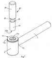
- a hinge 1 comprising an attachment element 2, for example cylindrical in shape, able to be constrained to a wall, not shown in the drawings, in proximity with or inside an opening, made in the wall and constituting the compartment for example for a door or window.
- the attachment element 2 is able to be partly inserted inside said wall, so that one end 2a protrudes therefrom, approximately orthogonally.
- the attachment element 2 supports a first pintle 3, of the female type, constrained thereto, for example cylindrical in shape, whose axis is arranged approximately orthogonally with respect to that of the attachment element 2.
- the first pintle 3 can have, as an alternative to the cylindrical shape, any prismatic shape whatsoever, for example with a square, rectangular, elliptical base or other.
- a first cavity 4 is made, cylindrical, open in correspondence with one upper end 5 of the first pintle 3.
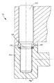
- the lateral surface of the first cavity 4 has an annular seating 6, whose profile comprises a first plane segment 7 (figs. 4 and 5), including a slight inclination, for example equal to about 15°, with respect to a diametric plane, the height of said first segment increasing as it is radially distanced from the axis X of the first cavity 4.
- the profile of the annular seating 6 also comprises a second segment 8, plane, consecutive to the first segment 7 and including a slight inclination, for example equal to about 15°, with respect to the axis X of the first cavity 4, and arranged in the direction of the narrowing of the annular seating 6, from the bottom upwards, along the axial direction.
- the annular seating 6 therefore comprises a throat, which defines an undercut formed by the two segments 7 and 8, inclined with respect to each other and arranged so that the transverse section of the annular seating 6 is substantially V-shaped.
- the second segment 8 is then connected at the upper part to a second surface 10, defining a third segment 11, plane, consecutive to said second segment 8 and inclined by about 45° with respect to the axis X of the first cavity 4.
- the third segment 11 is then connected to a first upper surface 9, plane, of the first pintle 3.
- the hinge 1 also comprises a bushing 12, with a circular shape (figs. 1, 2, 3 and 4), able to be associated in snap-in manner above the first pintle 3.
- the bushing 12 comprises an abutment body 13 (figs. 3 and 4), substantially T-shaped, defining a head 13a, plane, and at the lower part of which a third annular surface 14 (fig. 4) is defined, able to abut against the first upper surface 9 of the first pintle 3, so as to define the positioning of the bushing 12.
- a hole 12a is made, with a diameter substantially equal to that of the first cavity 4.
- a shank 13b protrudes at the lower part, having on the outside a fourth surface 15, with a profile consisting of a fourth segment 16, inclined with respect to the third annular surface 14 by an angle equal to that defined by the third segment 11, so that said fourth surface 15 corresponds with the second surface 10, defined on the first pintle 3, when the bushing 12 is coupled on the latter.
- the hole 12a made axially on the bushing 12, has in correspondence with the head 13a a diameter about equal to that of the first cavity 4, made inside the first pintle 3.
- the bushing 12 also comprises, below the shank 13b, an elastically deformable appendix 17, also with an annular conformation, whose outer profile is defined, along its outer surface, by a fifth segment 18, plane, consecutive to the fourth segment 16 and slightly inclined, by an angle for example equal to about 10° when the appendix 17 is inactive, in its non-deformed configuration, with respect to the axis X of the bushing 12, in the direction of the widening of the bushing 12 proceeding from the top downwards along the axis X of the latter.
- the angle formed by the fifth segment 18 with respect to the axis of the bushing 12, when the appendix 17 is in its non-deformed configuration, is less than the angle formed by the second rectilinear segment 8 with respect to the axis of the first cavity 4.
- the outer profile of the elastically deformable appendix 17 is defined at the lower part by a sixth segment 19, plane, consecutive to the fifth segment 18 and including an inclination, with respect to a horizontal direction, equal to that defined by the first segment 7.
- the inner profile of the appendix 17, starting from the lower end contiguous to the sixth segment 19, consists of a seventh segment 20, plane, approximately parallel to the axis X of the bushing 12, and of an eighth segment 21, consecutive to the seventh segment 20 and slightly inclined with respect thereto, facing from the bottom upwards in the direction of distancing from the axis X of the bushing 12.
- the seventh segment 20 is located, with the appendix in its non-deformed configuration, at a distance from the axis X of the bushing 12 less than the radius of the first cylindrical cavity 4, defining, in correspondence with the elastic appendix 17, a section 22 that is smaller than that of the hole 12a.
- the bushing 12 can be made for example of plastic material.
- a plurality of axial slits 12b (fig. 6), affecting the elastic appendix 17 and possible part of the shank 13b, can be made on the bushing 12, so as to further increase the elasticity of the elastic appendix 17.
- slits 12b there can be for example four slits 12b, positioned off-set circumferentially by about 90° one from the other.
- one or more of the edges of the profile of said bushing 12, corresponding to the joining points of two consecutive segments, can be rounded or bevelled.
- the hinge 1 also comprises a pin 23 (figs. 1 and 2), with a substantially cylindrical conformation including at the lower part a first zone 24, which extends from a first lower end 23a of the pin 23 for a length at least equal to the depth of the first cavity 4 present on the first pintle 3, and with a diameter a little less than that of the first cavity 4, so that it can be inserted therein with minimum play.
- a pin 23 (figs. 1 and 2), with a substantially cylindrical conformation including at the lower part a first zone 24, which extends from a first lower end 23a of the pin 23 for a length at least equal to the depth of the first cavity 4 present on the first pintle 3, and with a diameter a little less than that of the first cavity 4, so that it can be inserted therein with minimum play.
- a second zone 26 Adjacent to the first zone 24 of the pin 23 there is a second zone 26 which can have a diameter greater than that of the first zone 24, and possibly be connected thereto by means of a flare 27.
- annular throat 25 is made, with a smaller diameter than that of the first zone 24, and about equal to that of the reduced section 22 present on the bushing 12 in correspondence with the elastically deformable appendix 17.
- the annular throat 25 is made at a distance from the first end 23a of the pin 23 about equal to that between the annular seating 6 made on the first cavity 4 and the bottom of the first cavity; in this way, when the pin 23 is inserted inside the first pintle 3, the annular throat 25 is positioned in correspondence with the annular seating 6.
- the hinge 1 also comprises a second pintle 28, able to be removably constrained to a wing of a frame, not shown in the drawings.
- the second pintle 28 is, for example, cylindrical in shape and is provided axially with a second, through cavity 29, with a diameter a little more than that of the second zone 26 of the pin 23, so that the latter can be inserted therein with play.
- the second pintle 28 has a substantially plane lower surface 31, perpendicular to its longitudinal axis.
- the hinge 1 according to the invention is assembled by associating in snap-in manner the bushing 12 with the first pintle 3, in correspondence with the upper end 5 of the latter.
- the bushing 12 is inserted by means of a direct action along the axis X of the first cavity 4, so that its appendix 17 is positioned in correspondence with the annular seating 6.
- the elastically deformable appendix 17 interacts with the third segment 11 (fig. 4) of the annular seating 6, which imposes on the appendix 17 a deformation sufficient to allow the bushing 12 to pass and the appendix 17 to be housed inside the annular seating 6.
- the sixth segment 19 of the profile of the appendix 17 is in contact with the first segment 7 of the profile of the annular seating 6; the appendix 17 protrudes for a part inside the first cavity 4, while the fourth segment 16 and the fifth annular surface 15 abut respectively against the third segment 11 and the first upper surface 9 defined on the first pintle 3, in proximity with its upper end 5.
- the fifth segment 18, which constitutes the outer profile of the appendix 17, on the contrary is detached from the second segment 8 of the profile of the annular seating 6, so that between the bushing 12 and the annular seating 6 an interspace 30 is defined, which develops in an annular direction.
- the first pintle 3, on which the bushing 12 has been coupled, can therefore be constrained to a wall, by means of the attachment element 2, in correspondence or in proximity with the compartment of a window or door, so that the axis X of the first cavity 4 is arranged vertically, the aperture of said cavity facing upwards.
- the pin 23 can therefore be inserted, in correspondence with its first zone 24, inside the first cavity 4, through the hole 12a present on the head 13a of the bushing 12.
- the annular throat 25 is in correspondence with the appendix 17, so that the latter can re-acquire its non-deformed configuration, the inner part of its profile occupying the annular throat 25, so as to constitute clamping means to prevent the axial loosening of the pin 23.
- the diameter of the annular throat 25 can also be slightly more than that of the reduced section 22 of the hole 12a, so that the appendix 17 maintains, once the pin 23 has been completely inserted, a slight residual deformation.
- the second pintle 28 is positioned above the first pintle 3, so that the second zone 26 of the pin 23 is housed inside the second cavity 29 and the lower surface 31 rests on the head 13a of the bushing 12, clamping it.
- the wing of the frame, connected to the second pintle 28, is hence supported by the first pintle 3, by means of the bushing 12, and is free to rotate with respect to the pin 23, in order to achieve the opening and closing movement of said frame.
- the bushing 12 can advantageously be made of plastic material, equipped with good resistance to wear and with low friction coefficients, so as to render the rotation of the second pintle 28 homogeneous and free from jamming, even after long use or in the event of exposure to atmospheric agents.
- the assembly of the hinge 1 as described above is very simple, especially because the bushing 12 is univocally positioned on the first pintle 3 and hence automatically centered thereon; as a consequence the insertion of the pin 23 is very easy.
- An axial movement of the pin 23, facing upwards, entails an action in the same direction by the first zone 24 of the pin 23, in correspondence with the lateral wall of the annular throat 25 arranged below, on the portion of the sixth segment 19 of the profile of the appendix 17 protruding inside the annular throat 25 itself.
- the bushing 12 opposes resistance to a vertical movement, because its appendix 17, in order to pass over the upper edge of the annular seating 6, would have to be subject to a radial deformation directed towards the axis X of the bushing 12, which is however prevented precisely by the presence of the pin 23, which is in this way forced to remain inside the first cavity 4, at least until the force acting in the direction of extraction is so intense as to cause the appendix 17 to yield.
- a further obstacle to a vertical motion of the bushing 12 also derives from the weight of the wing of the frame supported by the hinge 1, which acts on the head 13a by means of the second pintle 28.
- a second form of embodiment of the hinge according to the invention differs from the embodiment described above in that it comprises, instead of the bushing 12, a sealing ring 135, open, that is, cut, and with a circular or polygonal section, preferably made of metal material.
- the sealing ring 135 can also be of the closed type and made of deformable material, such as rubber or plastic.
- the sealing ring 135 is located between the annular seating 106 and the annular throat 125, made on the pin 123.
- the sealing ring 135 constitutes a clamping means against the removal of the pin 123 from the pintle 103 since, as it is retained inside the annular throat 125, it acts, with a part protruding towards the inside of the annular throat 125, on the lateral wall of said annular throat arranged at the lower part.
- the method to achieve the pintle, but also a hinge, of the female type, which is also the object of the present invention, comprises a first step that consists in cutting, from a metal drawn piece, preferably with a circular section, a blank 52 (fig. 8).
- the forming of the pre-hole 54 is achieved by means of a first punching process, for which a first punch is used, of a known type and appropriately shaped. This first punching allows part of the material that constitutes the blank 52 to rise vertically, all around it.
- the first forming step thus achieves a slight increase in the height of the blank 52, due to the plastic deformation imposed, which however does not yet correspond to the definitive height.
- This height is obtained by means of a second punching, made on the pre-hole 54 by means of a second punch, also of a known type and suitably shaped.
- This second punching gives rise to the plastic displacement of material from the central zone of the blank 52 towards the upper and outer zones.
- the axial cavity 4 has a diameter of less than that of the pre-hole 54, so that, in proximity with the upper end of the axial cavity 4, a stepped zone 57 is defined.
- the method then provides to deform the stepped zone 57, by using a third, suitably shaped punch which plastically displaces the material, determining the creation of the annular seating 6 (fig. 11), which comprises the undercut throat defined by the segments 7 and 8 (fig. 5), and having a V-shaped transverse section. Consequently the upper flare is formed that defines the third segment 11.
- the method as described heretofore therefore allows to obtain a pintle, or a hinge, of the female type, that has all the characteristics of use proper to female hinges of a known type, with a suitably shaped annular seating, but with the advantage that it is obtained in a cold molding cycle, in a same machine, as previously specified, and hence without requiring the piece to be picked up in the various working sequences, nor any processing of chip removal.
- a further purpose obtained is that of achieving an invention that allows the rotation of the wings of a frame that is homogeneous and constant in time, even when it is exposed to the action of atmospheric agents.
- Another purpose obtained by the invention is that it achieves an aesthetically pleasing hinge, of limited size.
Landscapes
- Engineering & Computer Science (AREA)
- Mechanical Engineering (AREA)
- Pivots And Pivotal Connections (AREA)
Applications Claiming Priority (4)
| Application Number | Priority Date | Filing Date | Title |
|---|---|---|---|
| ITTV20030163 | 2003-12-19 | ||
| ITTV20030163 ITTV20030163A1 (it) | 2003-12-19 | 2003-12-19 | Procedimento per l'ottenimento di una cerniera femmina. |
| ITTV20030162 | 2003-12-19 | ||
| ITTV20030162 ITTV20030162A1 (it) | 2003-12-19 | 2003-12-19 | Cerniera, particolarmente per il sostegno di serramenti. |
Publications (1)
| Publication Number | Publication Date |
|---|---|
| EP1544392A1 true EP1544392A1 (fr) | 2005-06-22 |
Family
ID=34525110
Family Applications (1)
| Application Number | Title | Priority Date | Filing Date |
|---|---|---|---|
| EP04029974A Withdrawn EP1544392A1 (fr) | 2003-12-19 | 2004-12-17 | Charnière, particulièrement pour soutenir des cadres, et méthode pour atteindre au moins un de ses composants |
Country Status (1)
| Country | Link |
|---|---|
| EP (1) | EP1544392A1 (fr) |
Cited By (8)
| Publication number | Priority date | Publication date | Assignee | Title |
|---|---|---|---|---|
| EP1818486A2 (fr) | 2006-02-14 | 2007-08-15 | Rahrbach GmbH | Charnière réglable pour porte |
| EP1842997A1 (fr) * | 2006-04-07 | 2007-10-10 | ZF Lemforder Mecacentre | Gond d'articulation pour vantaux |
| FR2904351A1 (fr) * | 2006-07-28 | 2008-02-01 | Tordo Belgrano Sa Ets | Gond notamment pour l'articulation d'un vantail |
| DE202006019226U1 (de) * | 2006-12-19 | 2008-04-30 | Dr. Hahn Gmbh & Co. Kg | Band für Fenster, Türen u.dgl. |
| ES2306552A1 (es) * | 2005-10-05 | 2008-11-01 | Universidad De La Rioja | Bisagra para puertas, ventanas y similares. |
| FR3011264A1 (fr) * | 2013-09-27 | 2015-04-03 | Plastigond | Gond a structure modulaire, comportant des moyens de verrouillage du pivot dans le corps de gond |
| FR3094738A1 (fr) * | 2019-04-04 | 2020-10-09 | Etablissements Robert Ludmann | Paumelle, plus particulièrement pour armoire électrique |
| CN112338124A (zh) * | 2020-09-30 | 2021-02-09 | 贵州安大航空锻造有限责任公司 | 一种前翼作动筒支座梁锻件的锻造方法及预锻模 |
Citations (5)
| Publication number | Priority date | Publication date | Assignee | Title |
|---|---|---|---|---|
| GB2156898A (en) * | 1984-03-15 | 1985-10-16 | Worcester Parsons Limited | Hinges |
| EP0196599A1 (fr) * | 1985-04-05 | 1986-10-08 | OTLAV S.p.A. | Méthode de fabrication de charnières et charnières ainsi obtenues |
| FR2640674A3 (fr) * | 1988-12-16 | 1990-06-22 | Memo Spa | Charniere a axe d'articulation orientale |
| EP0467122A1 (fr) * | 1990-07-16 | 1992-01-22 | Dr. Hahn GmbH & Co. KG | Douille pour broches de ferrures ou charnières |
| EP1319785A2 (fr) * | 2001-12-13 | 2003-06-18 | van Parys, Remi Emiel | Charnière et élément de charnière correspondant |
-
2004
- 2004-12-17 EP EP04029974A patent/EP1544392A1/fr not_active Withdrawn
Patent Citations (5)
| Publication number | Priority date | Publication date | Assignee | Title |
|---|---|---|---|---|
| GB2156898A (en) * | 1984-03-15 | 1985-10-16 | Worcester Parsons Limited | Hinges |
| EP0196599A1 (fr) * | 1985-04-05 | 1986-10-08 | OTLAV S.p.A. | Méthode de fabrication de charnières et charnières ainsi obtenues |
| FR2640674A3 (fr) * | 1988-12-16 | 1990-06-22 | Memo Spa | Charniere a axe d'articulation orientale |
| EP0467122A1 (fr) * | 1990-07-16 | 1992-01-22 | Dr. Hahn GmbH & Co. KG | Douille pour broches de ferrures ou charnières |
| EP1319785A2 (fr) * | 2001-12-13 | 2003-06-18 | van Parys, Remi Emiel | Charnière et élément de charnière correspondant |
Cited By (11)
| Publication number | Priority date | Publication date | Assignee | Title |
|---|---|---|---|---|
| ES2306552A1 (es) * | 2005-10-05 | 2008-11-01 | Universidad De La Rioja | Bisagra para puertas, ventanas y similares. |
| ES2306552B1 (es) * | 2005-10-05 | 2009-09-16 | Universidad De La Rioja | Bisagra para puertas, ventanas y similares. |
| EP1818486A2 (fr) | 2006-02-14 | 2007-08-15 | Rahrbach GmbH | Charnière réglable pour porte |
| EP1818486A3 (fr) * | 2006-02-14 | 2007-12-05 | Rahrbach GmbH | Charnière réglable pour porte |
| EP1842997A1 (fr) * | 2006-04-07 | 2007-10-10 | ZF Lemforder Mecacentre | Gond d'articulation pour vantaux |
| FR2899625A1 (fr) * | 2006-04-07 | 2007-10-12 | Zf Lemforder Mecact Soc Par Ac | Gond d'articulation pour vantaux |
| FR2904351A1 (fr) * | 2006-07-28 | 2008-02-01 | Tordo Belgrano Sa Ets | Gond notamment pour l'articulation d'un vantail |
| DE202006019226U1 (de) * | 2006-12-19 | 2008-04-30 | Dr. Hahn Gmbh & Co. Kg | Band für Fenster, Türen u.dgl. |
| FR3011264A1 (fr) * | 2013-09-27 | 2015-04-03 | Plastigond | Gond a structure modulaire, comportant des moyens de verrouillage du pivot dans le corps de gond |
| FR3094738A1 (fr) * | 2019-04-04 | 2020-10-09 | Etablissements Robert Ludmann | Paumelle, plus particulièrement pour armoire électrique |
| CN112338124A (zh) * | 2020-09-30 | 2021-02-09 | 贵州安大航空锻造有限责任公司 | 一种前翼作动筒支座梁锻件的锻造方法及预锻模 |
Similar Documents
| Publication | Publication Date | Title |
|---|---|---|
| US4094490A (en) | Hard wall fastener | |
| US6874200B2 (en) | Hinge and hinge part therefor | |
| AU636503B2 (en) | Hinge housing | |
| EP2246516B1 (fr) | Couvercle à embout pour persienne | |
| EP1267691A1 (fr) | Separation de douche et profile utilise a cet effet | |
| JP4218921B2 (ja) | 対震蝶番及びその製造方法 | |
| KR200349137Y1 (ko) | 롤 블라인드의 브래킷 | |
| KR100493521B1 (ko) | 도어용 피벗힌지 및 피벗힌지용 베어링 | |
| KR20190002968A (ko) | 슬라이딩 도어용 피봇홀더 선택 설치형 연동장치 | |
| KR102709899B1 (ko) | 위치 조절 기능을 가진 경첩 | |
| KR20220145486A (ko) | 방수턱 거푸집용 고정부재 | |
| JP4749264B2 (ja) | 室内面格子の取付け機構 | |
| KR200300473Y1 (ko) | 방화문틀 구조 | |
| CN222436093U (zh) | 用于门窗结构件的操作把手 | |
| EP1030020B1 (fr) | Broche de charnière, en particulier pour chassis de fenêtre ou de porte, et procédé de fabrication | |
| KR200221617Y1 (ko) | 장식창용 형틀바 | |
| KR102414296B1 (ko) | 여닫이창에 설치되는 방충망 창호 | |
| KR102818155B1 (ko) | 손끼임 방지 도어 | |
| KR102249468B1 (ko) | 도어용 록 장치 | |
| KR102025185B1 (ko) | 연동 도어 장착용 도어 수직 프레임 | |
| EP2087189A1 (fr) | Poignée | |
| KR100663748B1 (ko) | 파티션 | |
| KR200300591Y1 (ko) | 도어용 힌지장치 | |
| KR200184340Y1 (ko) | 출입문의 손잡이를 겸한 도어록장치 | |
| KR200164815Y1 (ko) | 도어용 힌지 고정용 치구 |
Legal Events
| Date | Code | Title | Description |
|---|---|---|---|
| PUAI | Public reference made under article 153(3) epc to a published international application that has entered the european phase |
Free format text: ORIGINAL CODE: 0009012 |
|
| AK | Designated contracting states |
Kind code of ref document: A1 Designated state(s): AT BE BG CH CY CZ DE DK EE ES FI FR GB GR HU IE IS IT LI LT LU MC NL PL PT RO SE SI SK TR |
|
| AX | Request for extension of the european patent |
Extension state: AL BA HR LV MK YU |
|
| 17P | Request for examination filed |
Effective date: 20051220 |
|
| AKX | Designation fees paid |
Designated state(s): AT BE BG CH CY CZ DE DK EE ES FI FR GB GR HU IE IS IT LI LT LU MC NL PL PT RO SE SI SK TR |
|
| RAP1 | Party data changed (applicant data changed or rights of an application transferred) |
Owner name: OTLAV SPA |
|
| STAA | Information on the status of an ep patent application or granted ep patent |
Free format text: STATUS: THE APPLICATION IS DEEMED TO BE WITHDRAWN |
|
| 18D | Application deemed to be withdrawn |
Effective date: 20110701 |