EP1544404A1 - Grille à barreaux amovibles verrouillés - Google Patents
Grille à barreaux amovibles verrouillés Download PDFInfo
- Publication number
- EP1544404A1 EP1544404A1 EP04291015A EP04291015A EP1544404A1 EP 1544404 A1 EP1544404 A1 EP 1544404A1 EP 04291015 A EP04291015 A EP 04291015A EP 04291015 A EP04291015 A EP 04291015A EP 1544404 A1 EP1544404 A1 EP 1544404A1
- Authority
- EP
- European Patent Office
- Prior art keywords
- bars
- coupling
- section
- longitudinal
- bar
- Prior art date
- Legal status (The legal status is an assumption and is not a legal conclusion. Google has not performed a legal analysis and makes no representation as to the accuracy of the status listed.)
- Granted
Links
- 230000008878 coupling Effects 0.000 claims abstract description 87
- 238000010168 coupling process Methods 0.000 claims abstract description 87
- 238000005859 coupling reaction Methods 0.000 claims abstract description 87
- 230000010196 hermaphroditism Effects 0.000 claims description 6
- 238000005304 joining Methods 0.000 claims description 4
- 230000004323 axial length Effects 0.000 claims description 3
- 241000237858 Gastropoda Species 0.000 abstract 4
- 230000002457 bidirectional effect Effects 0.000 description 3
- 230000000873 masking effect Effects 0.000 description 3
- 238000007789 sealing Methods 0.000 description 3
- 230000000903 blocking effect Effects 0.000 description 2
- 229910003460 diamond Inorganic materials 0.000 description 2
- 239000010432 diamond Substances 0.000 description 2
- 230000009977 dual effect Effects 0.000 description 2
- 206010017577 Gait disturbance Diseases 0.000 description 1
- 230000000295 complement effect Effects 0.000 description 1
- 238000006880 cross-coupling reaction Methods 0.000 description 1
- 238000005520 cutting process Methods 0.000 description 1
- 230000003292 diminished effect Effects 0.000 description 1
- 230000005484 gravity Effects 0.000 description 1
- 238000007373 indentation Methods 0.000 description 1
- 239000007937 lozenge Substances 0.000 description 1
- 238000004519 manufacturing process Methods 0.000 description 1
- 239000002184 metal Substances 0.000 description 1
- 238000007747 plating Methods 0.000 description 1
- 230000000717 retained effect Effects 0.000 description 1
- 230000000630 rising effect Effects 0.000 description 1
- 125000006850 spacer group Chemical group 0.000 description 1
- 238000003860 storage Methods 0.000 description 1
- 230000001131 transforming effect Effects 0.000 description 1
- 238000003466 welding Methods 0.000 description 1
Images

Classifications
-
- E—FIXED CONSTRUCTIONS
- E06—DOORS, WINDOWS, SHUTTERS, OR ROLLER BLINDS IN GENERAL; LADDERS
- E06B—FIXED OR MOVABLE CLOSURES FOR OPENINGS IN BUILDINGS, VEHICLES, FENCES OR LIKE ENCLOSURES IN GENERAL, e.g. DOORS, WINDOWS, BLINDS, GATES
- E06B9/00—Screening or protective devices for wall or similar openings, with or without operating or securing mechanisms; Closures of similar construction
- E06B9/01—Grilles fixed to walls, doors, or windows; Grilles moving with doors or windows; Walls formed as grilles, e.g. claustra
Definitions
- the present invention relates to constituting a grid.
- a grid is constituted by a mesh of two mutually orthogonal sets of bars parallel metal welded together.
- some of the bars may have a shape shapely and, in addition, ironwork patterns may be welded between neighboring bars.
- a disadvantage of such grids is that the user can not customize them and furthermore the manufacturer must manage a stock of grids of all Possible sizes.
- GB 2 268 956 A teaches a grid comprising a horizontal bar with a side notch on which comes laterally by sliding a branch of a slider or elastic clip in a clothespin, pushed down to the horizontal bar to be imprisoned axially by the two sides of the notch.
- the slide thus fixed in axial position on the horizontal bar, is himself prisoner inside a vertical bar consisting of two opposite U-shaped angles.
- the present invention aims to simplify the assembly of locking in the mutual position of the bars.
- the invention relates first of all to a set of grid elements, including a first plurality of longitudinal bars each comprising a second plurality of securing sections with respectively a said second plurality of sections of coupling belonging to cross bars, characterized in that each coupling section has a transverse cut and each section of solidarisation comprises a segment of solidarity, shape and length adapted to be received in the cutting, segment limited by a shoulder of a relief lateral axial positioning arranged for then find axially opposite a stop surface making part of stop means belonging to the section of coupling considered.
- the shoulder opposes any lateral force that would be exercised, voluntarily or not, on the associated crossbar, and would be likely to separate it from a neighbor.
- This set of elements therefore presents itself, in storage, in the form of free elements, which are then assembled into a grid.
- the longitudinal bars extend substantially horizontally and transverse bars substantially vertically.
- first plurality and / or second plurality of bars can each be limited to one bar.
- the grid can for example be used to protect a opening or constitute a kind of ladder serving for example support for shelves.
- the section of coupling is of the female type, the cutout being a hole of cross coupling with a clearance template adapted to be able to ensure the free passage of a longitudinal bar when it forms an axis having an axis direction aligned with a template direction of passage defined by the hole, each section of solidarization being of the male type and the shoulder being arranged for, by misalignment between the axis directions and jig passage, come axially opposite the stop surface.
- So called horizontal bars are pins for the vertical bars that we put on slip, as long as the orientations of the associated sections agree, then the vertical bars are then locked in position by misalignment when they have reached the respective axial positions provided on the horizontal bars.
- the respective coupling sections and of solidarity are arranged so that misalignment obtained by axial rotation of at least one of the longitudinal bar and the crossbar considered or by a relative pivoting between the longitudinal bar and the associated crossbar.
- the user rotates each bar vertically around its axis and then seals at least two to at least one end without must seal the horizontal bars, prisoners of the vertical bars, or it turns each bar horizontal around its axis to position angularly said lateral relief axially opposite the abutment surface of the female coupling section.
- the user pivotally, the user assembles the bars according to a lattice forming mesh having the angle initial phase allowing the desired assembly between the bars, example of lozenges, then he deforms the lattice in his plan for the meshes to take the form intended for perform the desired locking, for example rectangles. In this case, only a minimum of points sealing to maintain the coupling.
- the shoulder is turned away from another shoulder, arranged to cooperate with another abutment surface forming part of abutment means.
- the coupling hole has a non-circular passage template with a recess to which is substantially adjusted a protuberance of the transverse profile of the bar longitudinal, except that the solidarisation has a recessed profile, limiting the bottom of a notch whose first edge is the said shoulder, the recessed profile existing over a length axial notch determined and being shaped provided for allow axial rotation of the male section so that the shoulder comes out of the jig passage.
- the notch preferably has a second edge, constituting the second shoulder, separated from the first edge at least one said notch length corresponding to a length of the coupling hole, to form a pair of jaws able to trap axially two mouths opposite of the coupling hole by respectively the first and second edges. Locking in position, in this embodiment, is thus provided in both directions.
- the securing notch can be separated axially into two sub-segments by a portion of a section having said protuberance, constituting an expected index to be received in a cavity in a wall of the coupling hole.
- the index thus ensures a lock bidirectional axial.
- the securing and securing sections respectively coupling can for example have edges respectively threaded and tapped, on at least one sector angular, rack, respectively corresponding to the lateral relief and abutment means. Locking Bidirectional is distributed.
- the securing section can present a lengthwise elongated cross-section reduced, however, having a length greater than said flattening width of the jig passage.
- the rotation of the longitudinal bar is thus limited to one angular sector, at one end of which it is engaged with the coupling hole, while it is free to a other end of the sector.
- the coupling holes respective two crossbars present between them a specular symmetry, so that the said rotation axial of the securing section, causing the exit of the shoulder off the clearance template, represents a relative shift in one direction from one of the two cross bars around the longitudinal bar, and represents a relative shift, in the opposite direction, of the other of the two crossbars.
- the respective holes, at a given height, bars cross-sections having been aligned it is first necessary to the successive transverse bars respectively of a side and the other of the planned plane of the grid, that is to say that it has a lateral profile in V. Then, by pivoting according to a given angular sector in a plane perpendicular to the planned common plane, each bar cross-section is folded into the planned common plane, thus transforming the profile of "V" into an "I".
- the clearance template may be intended to be gradually flattened by the misalignment of gauge direction of passage relative to the direction axis, following a said relative pivoting or a said rotation of the crossbar, until the clearance template does not fully enclose the shoulder.
- At least one pair of associated bars, longitudinal and transverse, is hermaphrodite, with respectively one said section of female coupling and a said male securing section. The mutual locking of the bars is thus better ensured.
- the set of bars can in particular comprise two so-called pairs of hermaphrodite bars planned for to form a parallelogram presenting a pair of couplings of a first type, inverse of the first type, that is to say dual, according to a diagonal and a pair of couplings of a second type according to another diagonal.
- the mesh of Mutual locking of the bars is thus optimal.
- the male section of a first longitudinal bar of this kind can be followed by another male stretch and the female section of a second longitudinal bar of this kind can be followed by another female stretch. It offers several possibilities for various montages of others bars.
- a crossbar that is to say, with holes coupling, can be provided to be mounted in position longitudinal coupling of the coupling hole with a cross-bar.
- Such a bar is therefore versatile because it can be transversal, and thus offer a hole in coupling and stop but it can just as well serve spindle for another crossbar, that is to say have the function of a longitudinal bar.
- This bar versatile will therefore have a reduced section to be able to cross the hole of the associated crossbar, or well the crossbar actually will have a hole with elongated section according to the extension direction of this crossbar, and the multi-purpose bar will present then an elongated section of the same.
- the bars longitudinal and transverse bars have said cutouts distributed on two opposite sides of the bars.
- Some of the longitudinal bars and transverse bars preferably comprise end sections arranged to be sealed.
- Some of the crossbars may present a folded conformation according to a decorative pattern determined size, with two coupling holes opposite and aligned, to be slipped on a single bar longitudinal, inserted between two transverse bars elongated each strung on the plurality of bars cross.
- the user can thus successively patterns of different shapes, for example in a circle, diamond, heart, S or other, on each of the bars longitudinal, and thus customize its grid.
- these patterns constitute spacers between the bars elongate transversals and contribute to blockage in translation of the other cross bars on the bars longitudinal.
- this form feature a crossbar is independent of the means, integrated or not, locking in position of the bars.
- the invention also relates to a transverse bar for forming a set of grid elements according to the invention, characterized by the fact that it comprises a said first plurality of coupling sections each having a cross cut, receiving a bar longitudinal, associated with abutment means comprising an abutment surface provided to cooperate with a shoulder of the longitudinal bar.
- the coupling section is preferably of the type female, the cutout being a transverse coupling hole having a clearance template adapted to be likely to ensure the free passage of a bar longitudinal when it forms an axis with a direction axis aligned with a clearance template direction defined by the coupling hole, the said cooperation of the stop surface being obtained by misalignment between axis directions and clearance gauge.
- the invention finally relates to a longitudinal bar to form a set of grid elements according to the invention, characterized in that it comprises a said second plurality of securing sections with respectively a said second plurality of sections of coupling belonging to transverse bars presenting reception cuts, each joining section including a segment of solidarity, shape and length adapted to be received in a said cut, segment limited by a shoulder of a lateral relief of Axial positioning arranged to then be found axially opposite an abutment surface forming part of stop means belonging to the coupling section considered.
- each securing section is then of the male type and the shoulder is arranged for, by misalignment between the axis and jig directions of passage, coming axially opposite the abutment surface.
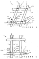
- Figures 1 to 4 show details of elements of coupling exposing the first embodiment of bars constituting a grid 1, serving as protection in this example, whose general appearance is represented on the Figures 5 and 6, which further expose the second form of production.
- grid 1 includes a first plurality of here two bars 2 and 3, said longitudinal, here identical and horizontal in this example and serving further here at anchor grid 1, and a second plurality of here two bars 4, 5, transversely extending, here orthogonal in final position (Fig. 6), compared at the longitudinal bars 2 and 3.
- the transverse bars 4, 5 are identical here and serve for masking a opening, not shown, whose excessive height forbidden to use only the two longitudinal bars 2 and 3, or whose excessive width would require bars longitudinal 2, 3 too long and therefore easy to dismiss mutually.
- the bars or bars 2 to 5 are rectilinear. It can be expected that the sections ends of the longitudinal bars 2, 3 have a Forked or other form of seal, not drawn, for to better anchor.
- the anchor requires that one of the two sets of bars 2, 3 and 4, 5 is more long as the corresponding dimension of the opening protected and that the other series of bars is shorter than the other dimension of the opening if the grid 1 extends next to the edge of the opening, we could consider that it is the crossbars that are anchored, in particular in a case for which they would be few, for example as here in the number of two.
- the longitudinal bars 2, 3 would then be used to maintaining the desired pitch between masking bars 4, 5.
- the anchor function is independent of the way to assemble the various bars 2 to 5.
- FIGS. 1 and 2 show a joining section 21 of the longitudinal bar 2 with the cross bar 4.
- the longitudinal bar 2 presents, in this example, a cross-section of substantially elliptical shape, or lenticular, that is to say, vertical oval around an axis geometric extension 20, here therefore horizontal, limited by two faces of small opposite planes sides 26 and 27, so-called upper and lower, and by two long sides or opposed curved faces 28 and 29, respectively back and front in Figure 1.
- the face upper 26 is thus limited by two edges upper longitudinal members 268 and 269, respectively back and front, while the underside 27 is limited by two lower longitudinal edges 278 and 279, respectively say back and front.
- the upper edge before 269 has a notch 24 with a substantially planar bottom 241, limited by two radial abutment flank surfaces 242 and 243, axially opposite and at a mutual distance defining a securing segment 22 corresponding to a value thickness of the crossbar 4.
- the bottom 241 is inclined forwardly since substantially the upper rear edge 268.
- the ridge lower rear 278 has a lower notch 25 (FIG 2) substantially identical to the notch 24, with a bottom 251, substantially parallel to the bottom 241, and two axially opposite thrust flanks 252 and 253.
- Figures 3 and 4 show a coupling section female 41 of crossbar 4 with the stretch of fastening 21, the coupling section 41 comprising a coupling hole 42 with walls substantially parallel to a global geometric axis 42A, defining a direction of clearance template for the passage of the bar longitudinal 2, direction 42A here perpendicular to an axis geometric 40 extension, here so vertical, of the bar crossbar 4.
- the crossbar 4 presents here a cross-section of substantially oval shape, and precisely in this example, identical to the section of the longitudinal bar 2.
- the cross section of the bar transversal 4 is limited by two small flat surfaces opposite, 46 and 47, respectively rear and front, and two large curved surfaces opposite 48 and 49, respectively from right and left in FIG.
- FIG. 4 represents the large right-hand surface 48, traversed by the coupling hole 42, the template of which general passage is mixed, that is to say that it corresponds to a superposition of two elementary passage templates mutually angularly offset.
- the first template of passage, of 42A1 geometric axis, allowing to skewer the crossbar 4 in an adjusted way, is identical to the substantially oval section of the longitudinal bar 2 (FIG 2), that is to say that it has an elongated shape, substantially in ellipse, approximately extension direction defined by axis 40, this shape elongated being here with axis of extension slightly inclined on this direction.
- the second jig of passage, axis geometric 42A2 is smaller, that is to say corresponds to the cross section of the segment of solidarisation 22, that is to say the first template of elementary passage but diminished by notches 24 and 25.
- the second passage template is generally of the same type of elongated shape substantially elliptical than the first clearance template and here it is extension axis perfectly parallel to the axis 40.
- the general passage template is limited by a small upper surface 426, intended for receive axial sliding the upper face 26, and by two large concave surfaces respectively rear 428 and before 429, intended to receive axial sliding respective large faces 28 and 29.
- the shape of the back surface 428 corresponds to that of the face rear 28 in the zone of segment 22, that is to say without the part of low surface that has disappeared because of the presence of the lower notch 25.
- the shape of the front surface 429 only corresponds to the part high, of the front face 29, located, outside the segment 22, to the height of the upper notch 24.
- the surface upper 426 descends to the rear side 46, of an angle, compared to a normal to the axis 40, of about here 10 degrees.
- the general passage template is limited by a large front surface 429A, with overall extension parallel to the vertical axis 40 in this example, intended for receive, as a lateral stop, the portion of the face before 29 located in the segment 22, that is to say axially at the notches 24 and 25.
- the front surface 429A is a complement of the surface before 429, their "sum” corresponding to the front face 29.
- the large area before 429A continues, to the front large area 429, by an oblique surface 424, intended to receive in look, with or without stop, the bottom 241 of the notch 24.
- a small lower surface 425 connects the bottom of the front surface 429A at the bottom of the back surface 428, rising at an angle corresponding to the slope of the bottom 251 of the lower notch 25.
- the space between the virtual extension of the upper part of the front surface 429 (first elementary passage template) and the surface before 429A (second elementary passage template) is a kind of side pocket offering a game allowing lateral movement, here essentially by axial rotation, of the longitudinal bar 2 when the axial advance of the segment 22 brings the upper cavity 24 opposite the front surface 429, located above the pocket mentioned above.
- the longitudinal bar 2 serves as a pin by passing through sliding in the coupling hole 42, the axis 20 being then collinear with the axis 42A1.
- the presence of the upper notch 24 causes the fact that the front face 429 no longer constitutes a lateral abutment, if although the longitudinal bar 2 can turn around its axis 20, until the front face 29 abuts, by its central and low parts, on the front surface 429A.
- the rotation of the bar longitudinal 2 is accompanied by a translation of the axis 20 remaining horizontal, with forward descent for become collinear with the 42A2 axis.
- this descent of the longitudinal bar when it locks is particularly interesting since gravity the will hold in place, so without need of sealing.
- the rotation of the longitudinal bar 2 takes place substantially around the ridge connecting the rear surfaces 428 and lower 425.
- the flanks 242 and 243 then constitute a pair of jaws axially opposite which are opposite two mouth areas 48B, 49B respectively of the surfaces of right 48 and left 49, thus trapping the cross bar 4, that is to say the blocking in the corresponding axial position on the longitudinal bar 2.
- the rotation of the bar longitudinal 2 causes the flanks 252 and 253 of the lower notch 25 come out of the jig passage global, that is to say, fall below the level of the surface lower slope 425 and form a second pair of jaws having the same function as the first pair of jaws or fangs 242, 243 of axial abutment against both respective mouth surfaces 48B and 49B.
- the longitudinal bar 2 could have a profile other, as if notch 25 extended over the entire length of the longitudinal bar 2, or the template of general passage could, correspondingly, be widened at the bottom.
- rotation of the axis 20 could, in variant, be free of lateral fall translation associated with this example or, on the contrary, be replaced by a simple lateral, horizontal and / or vertical.
- the notches 24 and 25 may be globally replaced by a length notch less than the length of the coupling hole 42, which then, in addition to the desired crossing template, function of the notch over a certain axial length of the hole 42, an enlarged jig size on the rest of its length.
- the template of fitted passage as described or its variants, may not wear only on a web, or rib, radial, protruding on the walls of the coupling hole 42.
- the notches 24 and 25 may be globally replaced by a dual relief, that is to say an index with radial extension coming to lodge, by rotation of the axis 20, in a lateral cavity or pocket constituting a radial groove in at least one of the front surfaces 429, 429A and rear 428.
- Notch 25, can be omitted and segment 22 is split into two sub-segments, or two sub-notches respectively.
- the index is equivalent to two flanks, turned the opposite, belonging to two notches axially adjacent.
- Notch 24, thus double, thus having the index in any axial position, can then extend, from both sides of the index, on any axial length desired.
- the coupling hole 142 has a template of passage having substantially the shape of the section of the longitudinal bar 2 and the securing segment 122 belonging to the securing section 121, with however, the clearance gauge axis or direction 142A of the coupling hole 142 and also slot 142F, inclined at a certain angle, about 25 degrees, compared to a normal to the so-called vertical axis 40. Seen according to this inclined orientation, the template of passage presents, in height, a set of determined size, that is to say that the edges of the slot 142F constitute, in view according to the axis 142A, two opposite lateral jaw hooks 142B, 142C.
- the axis 20 of the longitudinal bar 2 is first aligned parallel to the axis 142A and the longitudinal bar 2 can thus be introduced laterally into the coupling hole 142 through the slot 142F.
- the set of bars 2 to 5 thus mounted forms a parallelepiped mesh, in diamond.
- a relative pivoting in their plane common, between the longitudinal bars 2, 3 and the bars 4, 5, to form a mesh rectangular causes misalignment of the axis 20 by relative to the passage template axis direction 142A, this which brings two ends, of hook, diagonally opposite two jaws 142B and 142C facing two zones, respectively high and low of the front panel 128, grabbed and imprisoned.
- the face upper 126 has a shoulder lateral relief 126E, here in the form of a notch, and, alternatively, in the form of a protuberance.
- the shoulder 126E is intended to abut on the left mouth 149B, and the face lower 127 likewise has a shoulder notch 127E intended to abut on the mouth of the right 148B.
- the pair of jaws 142B and 142C here ensures both the Hold function of the longitudinal bar 2, by the ends of the jaws 124B and 142C laterally opposite, and the blocking function of the crossbar 4 in the desired axial position on the securing section 21 of the longitudinal bar 2, this by the base area of the jaws 142B and 142C which is located at the associated mouth 148B, 149B.
- the jaws 142B and 142C can therefore in fact be limited to two such fangs diagonally opposite each end of the coupling hole 142.
- the relative movement pivot between the two games bars 2, 3 and 4, 5 thus causes pinching or flattening of the height of the jig of passage, which entails the setting in cooperation of the lateral elements of stop, that is to say, on the one hand, the mouths 149B and 148B with respectively the shoulders 126E and 127E and, on the other hand, the fangs 142B, 142C with large faces before 128 and back 129.
- At least one pair 2, 4 bars associated, longitudinal and transverse is hermaphrodite, with, in addition to the respective sections of joining 21 or 121 and coupling 41 or 141, respectively, a coupling section 41 or 141, female, and a said securing section 21 or 121, male.
- the grid 1 can even include two such pairs 2, 4 and 3, 5 of hermaphrodite bars planned to form a parallelogram presenting a pair of couplings of a first type on a diagonal 42, 53 and a pair of couplings of a second type, inverse of the first type, according to another diagonal 43, 52. There is thus an inversion of male / female coupling, between the two bars considered, at the level of "junctions" 52 and 43.
- the longitudinal bar 2 may thus comprise, at level of its junction (52) with the crossbar 5, a female section, similar to hole 41, followed by a section male (21) as described in detail, and the bar longitudinal axis 3 may comprise, opposite (53), a section male 21, securing with the crossbar 5, tracking (43) of a female section 41 as described.
- the section male 21 ("junction" 142) of the longitudinal bar 2 can be followed by another male section (21), not drawn, and the female section (“junction” 43) of the longitudinal bar 3 can similarly be followed by another female stretch, no drawn.
- Such a configuration offers great freedom to add more bars 2 to 5.
- an additional bar of transverse type as the bars 4, 5, that is to say female with holes 142, to be mounted in longitudinal position, here horizontal, by coupling its coupling hole (s) 41 with one or more transverse bars 4, 5.
- the additional female bar then having its holes spaced at the desired horizontal pitch, is thus skewed in parallel by all crossbars 4, 5 and thus locks them to the desired horizontal pitch.
- the longitudinal bars 2, 3 may have, at the level of the fastening section 21, a lateral cavity profile substantially identical to that of the laterally open hole 142, to hold each other. It is thus formed of generally "C" profiles which fit together in mutually crossed position, at right angles or not. This is also valid for the first embodiment, with the lateral translation coupling mentioned above, although then a decoupling of the "U” allows only one sliding between bars, which would remain in the plane common, so without immediate disassembly. If the pivoting of locking is not provided, for example if the profiles are in “U” and not in "C”, it is then necessary to seal the ends of the bars to keep them coupled by keeping in the grid plan 1. It may, however, interleaving, that is to say that the indentations or slots 142F of some of the bars 2 to 5 are then distributed on the two large faces 28, 29 or 148, 149, which prevents any exit from the common plane.
- a rotation of the bar transverse 4 about its longitudinal axis 40 can be designed to pinch in width the template for the hole 42, 142, with the same provision for cooperation thrust reliefs.
Landscapes
- Engineering & Computer Science (AREA)
- Structural Engineering (AREA)
- Architecture (AREA)
- Civil Engineering (AREA)
- Mutual Connection Of Rods And Tubes (AREA)
Abstract
Description
- les figures 1 et 2 représentent, respectivement en perspective et en vue de bout, un tronçon d'une barre dite longitudinale, selon la première forme de réalisation,
- les figures 3 et 4 représentent, respectivement en perspective et en vue de côté, un tronçon d'une barre dite transversale, de masquage d'ouverture, comportant un trou de passage de la barre longitudinale, et
- les figures 5 et 6 sont des vues de face d'une grille selon la seconde forme de réalisation, respectivement en cours de montage et après montage.
Claims (23)
- Ensemble d'éléments de grille (1), comportant une première pluralité de barres longitudinales (2, 3) comprenant chacune une seconde pluralité de tronçons (21) de solidarisation avec respectivement une dite seconde pluralité de tronçons de couplage (41, 141) appartenant à des barres transversales (4, 5), caractérisé par le fait que chaque tronçon de couplage (41, 141) présente une découpe transversale (42, 142) et chaque tronçon de solidarisation (21) comprend un segment de solidarisation (22, 122), de forme et de longueur adaptées pour être reçue dans la découpe (42, 142), segment (22, 122) limité par un épaulement (242, 243) d'un relief latéral (24, 25) de positionnement axial agencé pour alors se trouver axialement en regard d'une surface de butée (248B, 249B) faisant partie de moyens de butée appartenant au tronçon de couplage (41, 141) considéré.
- Ensemble selon la revendication 1, dans lequel le tronçon de couplage (41, 141) est de type femelle, la découpe étant un trou de couplage transversal (42, 142) présentant un gabarit de passage adapté pour être susceptible d'assurer le libre passage d'une barre longitudinale (2, 3) lorsqu'elle forme un axe ayant une direction d'axe (20) alignée sur une direction de gabarit de passage (42A, 142A) définie par le trou (42, 142), chaque tronçon de solidarisation (21, 121) étant de type mâle et l'épaulement (242, 243) étant agencé pour, par désalignement entre les directions d'axe (20) et de gabarit de passage (42A, 142A), venir axialement en regard de la surface de butée (248B, 249B).
- Ensemble selon la revendication 2, dans lequel les tronçons respectivement de couplage (41) et de solidarisation (21) sont agencés pour que le désalignement soit obtenu par rotation axiale de l'une au moins parmi la barre longitudinale (2, 3) et la barre transversale (4, 5) considérées ou par un pivotement relatif entre la barre longitudinale (2, 3) et la barre transversale (4, 5) associée.
- Ensemble selon l'une des revendications 1 à 3, dans lequel l'épaulement (242, 243) est tourné à l'opposé d'un autre épaulement (243, 242), agencé pour coopérer avec une autre surface de butée (249B, 248B) faisant partie de moyens de butée.
- Ensemble selon l'une des revendications 2 à 4, dans lequel le trou de couplage (42) présente un gabarit de passage non circulaire, comportant un renfoncement auquel est sensiblement ajustée une protubérance du profil transversal de la barre longitudinale (2, 3), hormis le fait que le segment de solidarisation (22) présente un profil en retrait, limitant le fond d'une encoche de solidarisation dont un premier bord (242, 243) constitue le dit épaulement, le profil en retrait existant sur une longueur axiale d'encoche déterminée et étant de forme prévues pour permettre une rotation axiale du tronçon de solidarisation (21) afin que l'épaulement sorte du gabarit de passage.
- Ensemble selon la revendication 5, dans lequel l'encoche de solidarisation (24, 25) présente un second bord (243, 242), constituant le second épaulement, écarté du premier bord (242, 243) d'au moins une dite longueur d'encoche correspondant à une longueur du trou de couplage (42), pour constituer une paire de mâchoires aptes à emprisonner axialement deux embouchures opposées (248B, 249B) du trou de couplage (42, 142, par respectivement le premier bord (242) et le second bord (243).
- Ensemble selon l'une des revendications 5 et 6, dans lequel l'encoche de solidarisation (24, 25) est séparée axialement en deux sous-segments par une portion de tronçon comportant la dite protubérance, constituant un index prévu pour être reçu dans une cavité ménagée dans une paroi (428, 429, 429A) du trou de couplage (42).
- Ensemble selon l'une des revendications 5 à 7, dans lequel les tronçons respectivement de solidarisation (21) et de couplage (41) présentent des pourtours respectivement filetés et taraudés, sur au moins un secteur angulaire, de crémaillère, correspondant respectivement au relief latéral et aux moyens de butée.
- Ensemble selon la revendication 8, dans lequel, le gabarit de passage présentant une forme allongée de taille déterminée par deux parois opposées (428, 429) présentant un maximum déterminé de largeur d'aplatissement et dont au moins l'une porte un dit secteur de crémaillère, le tronçon de solidarisation (21) présente une section transversale de forme allongée de taille réduite présentant toutefois une longueur supérieure à la dite largeur d'aplatissement du gabarit de passage.
- Ensemble selon l'une des revendications 5 à 9, dans lequel les trous de couplage (42) respectifs de deux barres transversales (4, 5) présentent entre eux une symétrie spéculaire, pour que la dite rotation axiale du tronçon de solidarisation (21), provoquant la sortie de l'épaulement (242, 243) hors du gabarit de passage, représente un basculement relatif, dans un sens déterminé, de l'une des deux barres transversales (4, 5) autour de la barre longitudinale (2, 3), et représente un basculement relatif, dans un sens opposé, de l'autre des deux barres transversales (4, 5).
- Ensemble selon l'une des revendications 2 et 3 ensemble, et éventuellement l'une des revendications 4 à 10, dans lequel le gabarit de passage est prévu pour être progressivement aplati, par le désalignement de la direction de gabarit de passage (42A) par rapport à la direction d'axe (20), suite à un dit pivotement relatif ou une dite rotation de la barre transversale (4, 5), jusqu'à ce que le gabarit de passage n'englobe plus totalement l'épaulement (242, 243).
- Ensemble selon l'une des revendications 2 à 11, dans lequel au moins une paire (2, 4) de barres associées, longitudinale et transversale, est hermaphrodite, avec respectivement un dit tronçon de couplage (41) femelle et un dit tronçon de solidarisation (21) mâle.
- Ensemble selon la revendication 12, comportant deux dites paires (2, 4 et 3, 5) de barres hermaphrodites prévues pour former un parallélogramme présentant une paire de couplages d'un premier type selon une diagonale et une paire de couplages d'un second type, inverse du premier type, selon une autre diagonale.
- Ensemble selon la revendication 13, dans lequel le tronçon mâle (21) d'une première barre longitudinale (2) est suivi d'un autre tronçon mâle (21) et le tronçon femelle (41) d'une deuxième barre longitudinale (3) est suivi d'un autre tronçon femelle (41).
- Ensemble selon l'une des revendications 1 à 14, dans lequel les barres longitudinales (2, 3) et les barres transversales (4, 5) présentent des dites découpes (42, 142) réparties sur deux côtés opposés des barres (2, 3, 4, 5).
- Ensemble selon l'une des revendications 2 à 15, dans lequel une dite barre transversale (5) est prévue pour être montée en position longitudinale par couplage du trou de couplage (41) avec une barre transversale (4).
- Ensemble selon l'une des revendications 1 à 16, dans lequel certaines, parmi les barres longitudinales (2, 3) et les barres transversales (4, 5), comprennent des tronçons d'extrémité agencés pour être scellés.
- Ensemble selon l'une des revendications 2 à 17, dans lequel le gabarit de passage présente une forme allongée selon sensiblement une direction d'extension de la barre transversale considérée (4, 5).
- Ensemble selon l'une des revendications 1 à 18, dans lequel certaines des barres transversales (4, 5) présentent une conformation repliée selon un motif décoratif d'encombrement déterminé, avec deux trous de couplage opposés et alignés, pour être enfilées sur une seule barre longitudinale (2, 3), en insertion entre deux barres transversales allongées (4, 5) enfilées chacune sur la pluralité de barres longitudinales (2, 3).
- Barre transversale (2, 3) pour former un ensemble d'éléments de grille (1) selon l'une des revendications 1 à 18, caractérisée par le fait qu'elle comporte une dite première pluralité de tronçons de couplage (41) présentant chacun une découpe transversale (42, 43), de réception d'une barre longitudinale (2, 3), associée à des moyens de butée comprenant une surface de butée (248B, 249B) prévue pour coopérer avec un épaulement de la barre longitudinale (2, 3).
- Barre transversale selon la revendication 20, dans laquelle le tronçon de couplage (41) est de type femelle, la découpe étant un trou de couplage transversal (42, 43) présentant un gabarit de passage adapté pour être susceptible d'assurer le libre passage d'une barre longitudinale (2, 3) lorsqu'elle forme un axe ayant une direction d'axe (20) alignée sur une direction de gabarit de passage (42A, 142A) définie par le trou de couplage (42, 142A), la dite coopération de la surface de butée (248B, 249B) étant obtenue par désalignement entre les directions d'axe (20) et de gabarit de passage (42A, 142A).
- Barre longitudinale (2, 3) pour former un ensemble d'éléments de grille (1) selon des revendications 1 à 19, caractérisée par le fait qu'elle comporte une dite seconde pluralité de tronçons (21) de solidarisation avec respectivement une dite seconde pluralité de tronçons de couplage (41) appartenant à des barres transversales (4, 5) présentant des découpes de réception (42, 142), chaque tronçon de solidarisation (21) comprenant un segment de solidarisation (22), de forme et de longueur adaptées pour être reçu dans une dite découpe (42, 142), segment (22) limité par un épaulement (242, 243) d'un relief latéral de positionnement axial agencé pour alors se trouver axialement en regard d'une surface de butée (248B, 249B) faisant partie de moyens de butée appartenant au tronçon de couplage (41) considéré.
- Barre longitudinale selon la revendication 22, dans laquelle, le tronçon de couplage (41) étant de type femelle et la découpe étant un trou de couplage transversal (42, 43) présentant un gabarit de passage adapté pour être susceptible d'assurer le libre passage de la barre longitudinale (2, 3) lorsqu'elle forme un axe ayant une direction d'axe (20) alignée sur une direction de gabarit de passage (42A, 142A) définie par le trou de couplage (42, 142), chaque tronçon de solidarisation (21) est de type mâle et l'épaulement (242, 243) est agencé pour, par désalignement entre les directions d'axe (20) et de gabarit de passage(42A, 142A), venir axialement en regard de la surface de butée 248B, 249B).
Applications Claiming Priority (2)
| Application Number | Priority Date | Filing Date | Title |
|---|---|---|---|
| FR0314990 | 2003-12-19 | ||
| FR0314990A FR2864201B1 (fr) | 2003-12-19 | 2003-12-19 | Grille a barreaux amovibles verrouilles |
Publications (2)
| Publication Number | Publication Date |
|---|---|
| EP1544404A1 true EP1544404A1 (fr) | 2005-06-22 |
| EP1544404B1 EP1544404B1 (fr) | 2012-03-28 |
Family
ID=34508713
Family Applications (1)
| Application Number | Title | Priority Date | Filing Date |
|---|---|---|---|
| EP20040291015 Expired - Lifetime EP1544404B1 (fr) | 2003-12-19 | 2004-04-16 | Grille à barreaux amovibles verrouillés |
Country Status (2)
| Country | Link |
|---|---|
| EP (1) | EP1544404B1 (fr) |
| FR (1) | FR2864201B1 (fr) |
Citations (1)
| Publication number | Priority date | Publication date | Assignee | Title |
|---|---|---|---|---|
| US1782789A (en) * | 1928-11-30 | 1930-11-25 | Michelman Nathan | Grating |
-
2003
- 2003-12-19 FR FR0314990A patent/FR2864201B1/fr not_active Expired - Fee Related
-
2004
- 2004-04-16 EP EP20040291015 patent/EP1544404B1/fr not_active Expired - Lifetime
Patent Citations (1)
| Publication number | Priority date | Publication date | Assignee | Title |
|---|---|---|---|---|
| US1782789A (en) * | 1928-11-30 | 1930-11-25 | Michelman Nathan | Grating |
Also Published As
| Publication number | Publication date |
|---|---|
| FR2864201B1 (fr) | 2006-02-10 |
| FR2864201A1 (fr) | 2005-06-24 |
| EP1544404B1 (fr) | 2012-03-28 |
Similar Documents
| Publication | Publication Date | Title |
|---|---|---|
| EP0657672B1 (fr) | Dispositif de raccordement bout à bout de tronçons de chemins de câbles perforés | |
| EP3399123B1 (fr) | Kit pour réaliser une clôture, procédé de montage de la clôture a l aide de ce kit et clôture ainsi montée | |
| CA2574061A1 (fr) | Ensemble modulaire de rangement et de stockage | |
| EP0900037A1 (fr) | Siege compose d'elements assemblables | |
| FR2956590A1 (fr) | Jeu de construction | |
| FR2530937A1 (fr) | Bati porteur, notamment pour casier ou rayonnage | |
| EP1728962B1 (fr) | Dispositif pour l'attelage d'un tablier de volet roulant, et volet roulant equipe d'un tel dispositif | |
| EP1905299A1 (fr) | Châssis pour panier-siège de pêcheur | |
| EP1544404B1 (fr) | Grille à barreaux amovibles verrouillés | |
| EP1900303B1 (fr) | Feuille de matériau de construction | |
| EP1013197B1 (fr) | Meuble d'étagères | |
| EP2290174A1 (fr) | Poteau de clôture | |
| EP0770832A1 (fr) | Grille modulable | |
| EP1376807B1 (fr) | Dispositif de fixation rapide d'un conduit de cheminement de câbles à une paroi | |
| EP1617155B1 (fr) | Grille de ventilation | |
| EP4455429B1 (fr) | Panneau brise-vue ou d'occultation de clôtures en treillis rigide et son procédé de fixation | |
| FR2700724A1 (fr) | Etui pour une série d'outils, notamment de clés mâles coudées. | |
| FR2880640A1 (fr) | Dispositif de revetement de mur | |
| CH539406A (fr) | Bracelet, notamment bracelet de montre, et procédé de fabrication de celui-ci | |
| EP1838931B1 (fr) | Elements de construction et mur de soutenement realise avec de tels elements | |
| FR3132116A1 (fr) | Dispositif brise-vue ou d’occultation de clôtures en treillis rigide et panneau associé | |
| FR3165936A1 (fr) | Kit d’assemblage, ensemble comprenant un tel kit et procédé d’assemblage | |
| WO2001096681A2 (fr) | Poteau d'angle pour l'assemblage de panneaux isolants | |
| FR2852998A1 (fr) | Elements de grille de protection | |
| EP3346072B1 (fr) | Structure de store |
Legal Events
| Date | Code | Title | Description |
|---|---|---|---|
| PUAI | Public reference made under article 153(3) epc to a published international application that has entered the european phase |
Free format text: ORIGINAL CODE: 0009012 |
|
| AK | Designated contracting states |
Kind code of ref document: A1 Designated state(s): AT BE BG CH CY CZ DE DK EE ES FI FR GB GR HU IE IT LI LU MC NL PL PT RO SE SI SK TR |
|
| AX | Request for extension of the european patent |
Extension state: AL HR LT LV MK |
|
| 17P | Request for examination filed |
Effective date: 20051208 |
|
| AKX | Designation fees paid |
Designated state(s): BE DE GB |
|
| GRAP | Despatch of communication of intention to grant a patent |
Free format text: ORIGINAL CODE: EPIDOSNIGR1 |
|
| GRAS | Grant fee paid |
Free format text: ORIGINAL CODE: EPIDOSNIGR3 |
|
| GRAA | (expected) grant |
Free format text: ORIGINAL CODE: 0009210 |
|
| AK | Designated contracting states |
Kind code of ref document: B1 Designated state(s): BE DE GB |
|
| REG | Reference to a national code |
Ref country code: GB Ref legal event code: FG4D Free format text: NOT ENGLISH |
|
| REG | Reference to a national code |
Ref country code: DE Ref legal event code: R096 Ref document number: 602004037093 Country of ref document: DE Effective date: 20120524 |
|
| PGFP | Annual fee paid to national office [announced via postgrant information from national office to epo] |
Ref country code: DE Payment date: 20120426 Year of fee payment: 9 Ref country code: BE Payment date: 20120425 Year of fee payment: 9 |
|
| PGFP | Annual fee paid to national office [announced via postgrant information from national office to epo] |
Ref country code: GB Payment date: 20120426 Year of fee payment: 9 |
|
| PLBE | No opposition filed within time limit |
Free format text: ORIGINAL CODE: 0009261 |
|
| STAA | Information on the status of an ep patent application or granted ep patent |
Free format text: STATUS: NO OPPOSITION FILED WITHIN TIME LIMIT |
|
| 26N | No opposition filed |
Effective date: 20130103 |
|
| REG | Reference to a national code |
Ref country code: DE Ref legal event code: R097 Ref document number: 602004037093 Country of ref document: DE Effective date: 20130103 |
|
| BERE | Be: lapsed |
Owner name: ETS DECAYEUX Effective date: 20130430 |
|
| GBPC | Gb: european patent ceased through non-payment of renewal fee |
Effective date: 20130416 |
|
| PG25 | Lapsed in a contracting state [announced via postgrant information from national office to epo] |
Ref country code: DE Free format text: LAPSE BECAUSE OF NON-PAYMENT OF DUE FEES Effective date: 20131101 Ref country code: GB Free format text: LAPSE BECAUSE OF NON-PAYMENT OF DUE FEES Effective date: 20130416 Ref country code: BE Free format text: LAPSE BECAUSE OF NON-PAYMENT OF DUE FEES Effective date: 20130430 |
|
| REG | Reference to a national code |
Ref country code: DE Ref legal event code: R119 Ref document number: 602004037093 Country of ref document: DE Effective date: 20131101 |