EP1544448A2 - Feuille de base segmentée pour une tuyère et procédé de fabrication correspondant - Google Patents
Feuille de base segmentée pour une tuyère et procédé de fabrication correspondant Download PDFInfo
- Publication number
- EP1544448A2 EP1544448A2 EP04257660A EP04257660A EP1544448A2 EP 1544448 A2 EP1544448 A2 EP 1544448A2 EP 04257660 A EP04257660 A EP 04257660A EP 04257660 A EP04257660 A EP 04257660A EP 1544448 A2 EP1544448 A2 EP 1544448A2
- Authority
- EP
- European Patent Office
- Prior art keywords
- basesheet
- leading
- trailing
- segment
- leading edge
- Prior art date
- Legal status (The legal status is an assumption and is not a legal conclusion. Google has not performed a legal analysis and makes no representation as to the accuracy of the status listed.)
- Granted
Links
Images


Classifications
-
- F—MECHANICAL ENGINEERING; LIGHTING; HEATING; WEAPONS; BLASTING
- F02—COMBUSTION ENGINES; HOT-GAS OR COMBUSTION-PRODUCT ENGINE PLANTS
- F02K—JET-PROPULSION PLANTS
- F02K1/00—Plants characterised by the form or arrangement of the jet pipe or nozzle; Jet pipes or nozzles peculiar thereto
- F02K1/06—Varying effective area of jet pipe or nozzle
- F02K1/12—Varying effective area of jet pipe or nozzle by means of pivoted flaps
-
- B—PERFORMING OPERATIONS; TRANSPORTING
- B23—MACHINE TOOLS; METAL-WORKING NOT OTHERWISE PROVIDED FOR
- B23K—SOLDERING OR UNSOLDERING; WELDING; CLADDING OR PLATING BY SOLDERING OR WELDING; CUTTING BY APPLYING HEAT LOCALLY, e.g. FLAME CUTTING; WORKING BY LASER BEAM
- B23K11/00—Resistance welding; Severing by resistance heating
- B23K11/10—Spot welding; Stitch welding
- B23K11/11—Spot welding
- B23K11/115—Spot welding by means of two electrodes placed opposite one another on both sides of the welded parts
-
- B—PERFORMING OPERATIONS; TRANSPORTING
- B64—AIRCRAFT; AVIATION; COSMONAUTICS
- B64D—EQUIPMENT FOR FITTING IN OR TO AIRCRAFT; FLIGHT SUITS; PARACHUTES; ARRANGEMENT OR MOUNTING OF POWER PLANTS OR PROPULSION TRANSMISSIONS IN AIRCRAFT
- B64D33/00—Arrangement in aircraft of power plant parts or auxiliaries not otherwise provided for
- B64D33/04—Arrangement in aircraft of power plant parts or auxiliaries not otherwise provided for of exhaust outlets or jet pipes
-
- F—MECHANICAL ENGINEERING; LIGHTING; HEATING; WEAPONS; BLASTING
- F02—COMBUSTION ENGINES; HOT-GAS OR COMBUSTION-PRODUCT ENGINE PLANTS
- F02K—JET-PROPULSION PLANTS
- F02K1/00—Plants characterised by the form or arrangement of the jet pipe or nozzle; Jet pipes or nozzles peculiar thereto
- F02K1/78—Other construction of jet pipes
- F02K1/80—Couplings or connections
- F02K1/805—Sealing devices therefor, e.g. for movable parts of jet pipes or nozzle flaps
-
- B—PERFORMING OPERATIONS; TRANSPORTING
- B23—MACHINE TOOLS; METAL-WORKING NOT OTHERWISE PROVIDED FOR
- B23K—SOLDERING OR UNSOLDERING; WELDING; CLADDING OR PLATING BY SOLDERING OR WELDING; CUTTING BY APPLYING HEAT LOCALLY, e.g. FLAME CUTTING; WORKING BY LASER BEAM
- B23K2101/00—Articles made by soldering, welding or cutting
- B23K2101/001—Turbines
-
- F—MECHANICAL ENGINEERING; LIGHTING; HEATING; WEAPONS; BLASTING
- F05—INDEXING SCHEMES RELATING TO ENGINES OR PUMPS IN VARIOUS SUBCLASSES OF CLASSES F01-F04
- F05D—INDEXING SCHEME FOR ASPECTS RELATING TO NON-POSITIVE-DISPLACEMENT MACHINES OR ENGINES, GAS-TURBINES OR JET-PROPULSION PLANTS
- F05D2230/00—Manufacture
- F05D2230/20—Manufacture essentially without removing material
-
- Y—GENERAL TAGGING OF NEW TECHNOLOGICAL DEVELOPMENTS; GENERAL TAGGING OF CROSS-SECTIONAL TECHNOLOGIES SPANNING OVER SEVERAL SECTIONS OF THE IPC; TECHNICAL SUBJECTS COVERED BY FORMER USPC CROSS-REFERENCE ART COLLECTIONS [XRACs] AND DIGESTS
- Y10—TECHNICAL SUBJECTS COVERED BY FORMER USPC
- Y10T—TECHNICAL SUBJECTS COVERED BY FORMER US CLASSIFICATION
- Y10T29/00—Metal working
- Y10T29/49—Method of mechanical manufacture
- Y10T29/49346—Rocket or jet device making
Definitions
- This invention relates generally to gas turbine engine nozzles and, more particularly, to methods and apparatus for sealing gas turbine engine nozzles with segmented flap basesheets.
- variable geometry exhaust nozzles varies throat and exit areas of the exhaust nozzle using flaps and seals.
- flaps and seals are the General Electric F110 and the F414.
- the flaps and seals define the flowpath and the seals as their name implies seal against adjacent flaps. Because the exhaust nozzles are subjected to high temperatures and thermal gradients as a result of hot combustion gases exiting the engine, the variable geometry nozzle must maintain a coherent flowpath while shielding nozzle structural components.
- each flap basesheet is unshielded and exposed to the combustion gases.
- the flap basesheet edges are exposed to less heat than the center portion of the basesheet, and as a result, a circumferential thermal gradient may be induced to the basesheet.
- Continued operation with the thermal gradient may induce thermal stresses into the basesheet which over time, may lead to warping, thermally induced distortion, cracking, or premature failure of the flaps.
- At least some known engines include a "floating" basesheet design. More specifically, within such designs, a unitary basesheet is used to establish a portion of the flowpath. Because the basesheet is not rigidly joined to the backbone, the basesheet may thermally expand more than the backbone, thus facilitating reducing thermal gradients in comparison to designs having basesheets that are attached rigidly to or formed integrally with the backbone. However, because the center portion of the associated flap basesheets are still exposed to the hot combustion gases, thermal gradients between the basesheet edges and basesheet center portion may cause warping, cracking, or thermally induced distortion within the flap assembly.
- One known flap incorporates a longitudinally segmented basesheet design having a central portion connected to the edge portions by channels which are crimped on the basesheet.
- the channels extend across and are attached to a backside of the basesheet and facilitate reducing thermally induced stresses by permitting differential thermal growth of the predominately cold portion of the seal assembly and the predominately hot portion of the segmented basesheet.
- aligning the basesheets while attaching the channel to the backside of the basesheets may be time consuming.
- continued thermal cycling may create local stress concentrations between the channel and the basesheet.
- a method for assembling a gas turbine engine variable exhaust nozzle having flaps with backbone and basesheet assemblies is disclosed in U.S. Patent Application No. 10/061,618, entitled “Methods and Apparatus for Sealing Gas Turbine Engine Nozzles", filed February 1, 2002, and published August 7, 2003.
- the method includes providing a flap basesheet having a width defined between a pair of side edges extending between a leading edge and a trailing edge.
- At least one stiffener extends between the basesheet side edges and includes an intermediate portion that has a width that is smaller than that of the basesheet.
- the stiffener is bonded to or formed integrally with the basesheet.
- the basesheet is mounted to the gas turbine engine exhaust nozzle with a backbone assembly. Other embodiments are described in the publication.
- a basesheet in accordance with the invention for use in a flap of a gas turbine engine exhaust nozzle includes a plurality of basesheet segments extending between basesheet longitudinally extending spaced apart basesheet leading and trailing edges, respectively, of the basesheet. Right and left hand basesheet side edges, respectively, extending longitudinally between the basesheet leading and trailing edges.
- Each basesheet segment includes a panel body defined between a pair of segment side edges longitudinally extending between segment leading and trailing edges, respectively. Stiffeners having leading and trailing edge ribs at the segment leading and trailing edges of aft and forward ones of the basesheet segments, respectively, extend widthwise across the panel body.
- leading and trailing edge ribs are joined together only at intermediate sections of the stiffeners centered between left and right hand expansion sections, respectively, of the stiffener.
- Forwardly extending side trailing edge flanges of the trailing edge ribs in the left and right hand expansion sections of the stiffeners are connected substantially parallel to the panel bodies of the basesheet segments by a hem at the segment leading edges.
- Forwardly extending side leading edge flanges of the leading edge ribs in the left and right hand expansion sections of the stiffeners are connected substantially parallel to the panel bodies of the basesheet segments by jogs in the leading edge ribs at the segment leading edges.
- the side leading edge flanges have rolled over tabs bent inwardly towards the panel bodies.
- the exemplary embodiment of the basesheet includes each of the stiffeners having a forwardly extending intermediate trailing edge flange of the trailing edge rib in the intermediate section of the stiffener connected, so as to be substantially parallel to the panel body of the forward basesheet segment, by the hem.
- a forwardly extending intermediate leading edge flange of the leading edge rib in the intermediate section of the stiffener is connected substantially parallel to the panel body by a jog at the segment leading edge of the aft basesheet segment.
- the leading edge and trailing edge ribs of each stiffener are joined together only along the intermediate trailing and leading edge flanges.
- the intermediate trailing and leading edge flanges are resistance welded together with spot welds centered on the intermediate trailing and leading edge flanges.
- An exemplary method of forming the stiffeners includes resistance welding together each pair of adjacent ones of the intermediate trailing and leading edge flanges by placing the copper shunt between and contacting both the intermediate trailing edge flange and the panel body to which the intermediate trailing edge flange is connected by the hem. Then pressing a first electrode against the intermediate leading edge flange, pressing a second electrode against the intermediate trailing and leading edge flanges, and using the electrodes to weld the pair of intermediate trailing and leading edge flanges together.
- the resistance welding may be resistance spot welding.
- a more general application of the resistance welding method can be applied to joining first and second sheet metal elements using the copper shunt between and in contact with the first sheet metal element and a third sheet metal element.
- the third sheet metal element being spaced apart from and connected to the first sheet metal element.
- a second sheet metal element is placed in contact with the first sheet metal element along an interface between the first and second sheet metal elements.
- the first electrode is pressed against the second sheet metal element and the second electrode is pressed against the first sheet metal element.
- the welding current is passed between the electrodes through the copper shunt, thus, welding the first and second sheet metal elements together along the interface.
- FIGS. 1 and 2 Illustrated in FIGS. 1 and 2 is a gas turbine engine variable geometry exhaust nozzle 20 including convergent flaps 32 and seals 174 and divergent flaps 40 and seals 172.
- Flowpath sides 42 of the divergent flaps 40 are exposed to hot exhaust gases 43 exiting the exhaust nozzle 20 and, thus, flowpath sides 42 define a portion of a flowpath 36 through the nozzle.
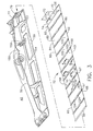
- FIG. 3 Illustrated in FIG. 3 is a partially exploded view of the divergent flap 40 which includes a longitudinally extending backbone 50 supporting a frame 53 for holding a removable basesheet 52.
- the basesheet 52 is constructed from a plurality of basesheet segments 80 connected together.
- the frame 53 is more particularly illustrated in cross-section in FIG. 6.
- the frame 53 supports a widthwise extending out-rigger 152 and includes longitudinally extending axial ribs 150.
- the cross-ribs 154 extend widthwise outwardly from the extending axial rib 150 of the frame 53.
- the basesheet 52 has right and left hand basesheet side edges 60 and 62, respectively, extending longitudinally between spaced apart basesheet leading and trailing edges 56 and 58.
- the basesheet 52 is slidably mounted to the frame 53 by the right and left hand basesheet side edges 60 and 62 as more particularly illustrated in FIG. 6.
- the right and left hand basesheet side edges 60 and 62 slidingly engage longitudinally extending frame slots 55 of rails 57 along frame side edges 59 of the frame 53 which are supported by the cross-ribs 154.
- the basesheet 52 is slid into the frame slots 55 of the rails 57.
- the basesheet side edges 60 and 62 are tapered inwardly in the forward or upstream direction from the basesheet trailing edge 58 to the basesheet leading edge 56 such that the basesheet trailing edge 58 is wider than the basesheet leading edge 56.
- the basesheet side edges 60 and 62 may be substantially parallel, and the basesheet leading and trailing edges 56 and 58, respectively, may be substantially parallel, and substantially perpendicular with respect to the basesheet side edges 60 and 62.
- the basesheet trailing edge 58 includes an aft retaining bend 70 on an aftmost basesheet segment 82.
- a retaining flange 71 of the retaining bend 70 is bent so as to be substantially normal to the basesheet 52.
- the retaining flange 71 includes retainer slots 73 which are used to secure the basesheet 52 to the frame 53 of the backbone 50.
- the retaining bend 70 and the retaining flange 71 are formed integrally with the aftmost basesheet segment 82 of the basesheet 52.
- the retaining bend 70 has a retaining bend width 72 that is less than a basesheet width 74 between the basesheet side edges 60 and 62 of basesheet 52.
- the basesheet segments 80 are identical except for the aftmost basesheet segment 82 which includes the basesheet trailing edge 58 and the retaining flange 70.
- the basesheet segments 80 are fabricated from a metallic material in the embodiment illustrated herein, but may otherwise be fabricated from different materials such as a silicon-carbon graphite material.
- the basesheet segments 80 are connected together, as described below, and extend between the basesheet leading and trailing edges 56 and 58, respectively, and between basesheet side edges 60 and 62.
- Each basesheet segment 80 has a panel body 92 defined between a pair of right and left hand segment side edges 84 and 86 longitudinally extending between segment leading and trailing edges 88 and 90, respectively.
- the panel body 92 is tapered inwardly as is the basesheet 52, the segment side edges 84 and 86 are angled inwardly, and the segment leading and trailing edges 88 and 90 are substantially parallel.
- edges 88 and 90 are substantially perpendicular to the segment side edges 84 and 86.
- a leading edge rib 96 is formed integrally with the panel body 92 at the segment leading edge 88 and extends widthwise across the panel body 92 between the segment side edges 84 and 86. The leading edge rib 96 is bent over.
- a bent over trailing edge rib 97 having a segment channel 100 is integrally formed with the panel body 92 at the basesheet segment trailing edge 90 and extends widthwise across panel body 92 between the segment side edges 84 and 86.
- the channel 100 is semi-circular and, thus, substantially arcuate such that channel 100 has a curved cross-section 103 that enables the channel 100 to conform to the leading edge rib 96.
- Each segment panel body 92 has a flowpath side 101 that is adjacent the nozzle exhaust flowpath, and a back side 102 that is between flowpath side 101 and backbone 50.
- the channel 100 is contoured to mate against an adjacent one of the leading edge ribs 96 to form a stiffener 106 that extends widthwise across panel body 92.
- leading edge and trailing edge ribs 96 and 97 provide increased structural integrity of each respective basesheet segment 80 and the stiffener 106 is designed to prevent the basesheet 52 from warping and also prevents vibrations by providing a tight fit in the frame slots 55 of the rails 57.
- Adjacent basesheet segments 80 are securely connected together to form the basesheet 52 and to form the stiffeners 106. Adjacent basesheet segments 80 are connected at the stiffeners 106. Aft and forward ones 105 and 109 of the adjacent basesheet segments 80 are welded, brazed, or otherwise joined or bonded together at the stiffeners 106. The adjacent basesheet segments 80 are bonded together only at an intermediate section 110 of each of the stiffeners 106. Bonding of the basesheet segments 80 at the intermediate sections 110 forms a basesheet 52 that is contiguous through the intermediate sections 110.
- Each stiffener intermediate section 110 has a width 112 that is smaller than basesheet width 74. In the exemplary embodiment, stiffener intermediate section width 112 is approximately equal one third of basesheet assembly width 74.
- the intermediate section 110 is centered between left and right hand expansion sections 116 and 118, respectively, of the stiffener 106.
- the left and right hand expansion sections 116 and 118 extend between the right and left hand basesheet side edges 60 and 62, respectively, and the intermediate section 110.
- the intermediate section 110 is delineated from the left and right hand expansion sections 116 and 118, respectively, by rounded notches 124.
- the intermediate section 110 is constructed differently than the left and right hand expansion sections 116 and 118, respectively, of the stiffener 106 as illustrated in FIGS. 4 and 5. Cross-sections of the intermediate section 110 are illustrated in FIG. 4 and the left and right hand expansion sections 116 and 118 are illustrated in FIG. 5.
- the bent over trailing edge rib 97 in the intermediate section 110 has a segment channel 100.
- the leading edge rib 96 is formed integrally with the segment leading edge 88 and extends widthwise across the panel body 92 between the segment side edges 84 and 86.
- the leading edge rib 96 is bent over and, in the embodiment illustrated herein, has a substantially semi-circular annular cross-section. Rib 96 facilitates increasing a structural integrity of each respective basesheet segment 80.
- a bent over trailing edge rib 97 having a segment channel 100 is integrally formed with the basesheet segment trailing edge 90 and extends widthwise across panel body 92 between the segment side edges 84 and 86.
- the channel 100 is substantially arcuate such that channel 100 has a curved cross-section 103 that enables the channel 100 to conform to the leading edge rib 96.
- Each segment panel body 92 has a flowpath side 101 that is adjacent the nozzle exhaust flowpath, and a back side 102 that is between flowpath side 101 and backbone 50.
- the channel 100 is contoured to mate against an adjacent one of the leading edge ribs 96 to form a stiffener 106 that extends widthwise across panel body 92.
- the stiffener 106 is designed to prevent the basesheet 52 from warping and also prevents vibration by providing a tight fit in the frame slots 55 of the rails 57.
- the bent over trailing edge rib 97 in the intermediate section 110 of the stiffener 106 has a forwardly extending intermediate trailing edge flange 120 connected, so as to be substantially parallel to the panel body 92 of the basesheet segment 80, by a hem 94 at the segment trailing edge 90.
- the leading edge rib 96 in the intermediate section 110 of the stiffener 106 has a forwardly extending intermediate leading edge flange 122 connected substantially parallel to the panel body 92 of the basesheet segment 80 by a jog 107 at the segment leading edge 88.
- the intermediate trailing edge flange 120 is parallel to and substantially in contact with the intermediate leading edge flange 122 because the channel 100 of the trailing edge rib 97 conforms to the leading edge rib 96.
- This design allows the intermediate trailing and leading edge flanges 120 and 122 to be joined or bonded together, such as by welding or brazing, only at the intermediate trailing and leading edge flanges 120 and 122.
- the leading edge and trailing edge ribs 96 and 97 of each stiffener 106 are joined together only along the intermediate trailing and leading edge flanges 120 and 122.
- the embodiment of the basesheet 52 illustrated herein has 3 spot welds 99 centered on the intermediate trailing and leading edge flanges 120 and 122.
- FIG. 7 Illustrated in FIG. 7 is a copper shunt 128 that is positioned between the intermediate trailing edge flange 120 and the panel body 92 at the basesheet segment trailing edge 90 before welding together the intermediate trailing and leading edge flanges 120 and 122.
- the copper shunt 128 remains between the intermediate trailing and leading edge flanges 120 and 122 during welding providing an electron path to the interface 132 between the flanges and also providing pressure and, thus, good contact between the flanges at the interface.
- a method for making a gas turbine engine exhaust nozzle basesheet 52 includes forming a plurality of the basesheet segments 80.
- the leading and trailing edge ribs 96 and 97 are formed at the segment leading and trailing edges 88 and 90 of aft and forward ones 105 and 109 of the basesheet segments 80, respectively, extending widthwise across the panel body 92 between the segment side edges 84 and 86 as illustrated in FIG. 2.
- the forwardly extending intermediate trailing edge flanges 120 are formed between the pairs of the forwardly extending side trailing edge flanges 142 of the trailing edge ribs 97 as illustrated in FIGS. 4 and 5.
- the forwardly extending intermediate trailing edge flanges 120 are formed connected substantially parallel to the panel bodies 92 of the respective basesheet segments 80 by hems 94.
- the forwardly extending intermediate leading edge flanges 122 as illustrated in FIG. 4 are formed between pairs of the forwardly extending side leading edge flanges 144 of the leading edge ribs 96 as illustrated in FIGS. 2 and 5.
- the forwardly extending intermediate leading edge flanges 122 are formed connected substantially parallel to the panel bodies 92 of the respective basesheet segments 80 by the jogs 107.
- the leading edge and trailing edge ribs 96 and 97 are welded together only along the intermediate trailing and leading edge flanges 120 and 122 as illustrated in FIG. 7.
- the intermediate trailing and leading edge flanges 120 and 122 are welded together by resistance welding, and in the exemplary embodiment illustrated herein, by resistance spot welding. Each pair of the intermediate trailing and leading edge flanges 120 and 122 are welded together by placing the copper shunt 128 between and contacting both the intermediate trailing edge flange 120 and the panel body 92 to which the intermediate trailing edge flange 120 is connected by the hem 94.
- the method further includes pressing a first electrode 180 against the intermediate leading edge flange 122, pressing a second electrode 182 against the intermediate trailing and leading edge flanges 120 and 122, and using the electrodes to weld the pair of intermediate trailing and leading edge flanges 120 and 122 together.
- the resistance welding may be resistance spot welding.
- the method may include, before the resistance welding, forming the rolled over tabs 148 of the side leading edge flanges 144. The rolled over tabs 148 are bent inwardly towards the panel bodies 92.
- a more general application of the resistance welding method can be applied to joining first and second sheet metal elements 200 and 202 together as also illustrated in FIG. 7.
- the copper shunt 128 is placed between and in contact with the first sheet metal element 200 and a third sheet metal element 204.
- the third sheet metal element 204 being spaced apart from and connected to the first sheet metal element 200.
- a second sheet metal element 202 is placed in contact with the first sheet metal element 200 along an interface 132 between the first and second sheet metal elements 200 and 202.
- the first electrode 180 is pressed against the second sheet metal element 202 and the second electrode 182 is pressed against the first sheet metal element 200.
- the welding current is passed between the electrodes through the copper shunt, thus, welding the first and second sheet metal elements 200 and 202 together along the interface 132.
- the trailing edge rib 97 has forwardly extending side trailing edge flanges 142 connected substantially parallel to the panel body 92 of the basesheet segment 80 by the hem 94.
- the leading edge rib 96 has forwardly extending side leading edge flanges 144 connected substantially parallel to the panel body 92 of the basesheet segment 80 by the jog 107 in the leading edge rib 96 at the segment leading edge 88.
- the side trailing edge flanges 142 are parallel to and substantially in contact with the side leading edge flanges 144 because the channel 100 of the trailing edge rib 97 conforms to the leading edge rib 96.
- the side trailing and leading edge flanges 142 and 144 are not bonded together and are thus free to expand and contract substantially independently of each other.
- the side trailing edge flanges 142 are substantially shorter than the side leading edge flanges 144. This allows the side leading edge flanges 144 to have rolled over tabs 148 that are bent inwardly towards the panel body 92 at the basesheet segment trailing edge 90.
- the rolled over tabs 148 shields sharp edges of the stiffener 106 from the support structure of the frame such as the cross-ribs 154 of the frame 53 during installation and removal.
- the basesheet 52 is assembled and slid into the frame slots 55.
- the basesheet 52 is secured to the backbone 50 by the retaining flange 70 having retaining slots 73 therethrough.
- Frame studs 79 extend aftwardly from an aft frame flange 77 that is normal to the frame 53.
- the frame studs 79 extend through the retaining slots 73.
- the retaining flange 70 is trapped between the aft frame flange 77 and a retainer 75 which is secured to the frame studs 79.
- adjacent basesheet segments 80 are positioned such that a leading basesheet segment trailing edge channel 100 is mated against a trailing basesheet segment leading edge rib 96 to form stiffener 106.
- the intermediate trailing and leading edge flanges 120 and 122 are then joined or bonded together, using for example welding or brazing, and the left and right hand expansion sections 116 and 118 remain in contact but not bonded or otherwise secured to each other.
- the basesheet 52 is then mounted to backbone 50 and positioned such that the divergent flap 40 extends in an overlapping fashion between a pair of adjacent exhaust nozzle variable geometry divergent seals 172 as illustrated in FIGS. 2 and 6.
- Each basesheet 52 forms a portion of the exhaust flowpath through the engine, such that adjacent basesheet edges 60 and 62, facilitate shielding exhaust nozzle flap backbone 50 from hot combustion gases exiting the engine.
- a center portion 140 of each basesheet 52 is exposed directly to hot combustion gases exiting the exhaust nozzle.
- the basesheet's center portion 140 extends axially between the basesheet leading and trailing edges 56 and 58, respectively, along the contiguous portion formed by stiffener intermediate portions. Additionally, the areas of basesheet 52 adjacent to the exposed center portion 140 and bounded by either edge 60 or 62 are substantially shielded from the hot combustion gases.
- basesheet assembly center portion 140 is exposed directly to hot combustion gases exiting the engine and as a result, basesheet assembly center portion 140 may thermally expand more than portions of basesheet 52 adjacent basesheet side edges 60 and 62 which are exposed to lower temperatures. As the center portion 140 thermally expands, the left and right hand expansion sections 116 and 118 may separate, thus, facilitating reducing thermally induced strains and stresses into basesheet 52 and flap 40.
- Each stiffener 106 includes an intermediate section that has a width that is less than the basesheet 52.
- a pair of expansion sections extend between the intermediate section and each respective basesheet assembly side.
- the basesheet is only contiguous through the intermediate sections of the stiffeners and as such, during operation, the expansion sections may separate and reduce thermal stresses induced to the basesheet. This extends the useful life of basesheet and results in the gas turbine engine variable geometry flap and nozzle being more cost-effective and reliable than other designs.
Landscapes
- Engineering & Computer Science (AREA)
- Mechanical Engineering (AREA)
- Chemical & Material Sciences (AREA)
- Combustion & Propulsion (AREA)
- General Engineering & Computer Science (AREA)
- Aviation & Aerospace Engineering (AREA)
- Supercharger (AREA)
- Resistance Welding (AREA)
- Exhaust Silencers (AREA)
- Turbine Rotor Nozzle Sealing (AREA)
Applications Claiming Priority (2)
| Application Number | Priority Date | Filing Date | Title |
|---|---|---|---|
| US740930 | 1985-06-03 | ||
| US10/740,930 US6935118B2 (en) | 2003-12-19 | 2003-12-19 | Exhaust nozzle segmented basesheet and production method thereof |
Publications (3)
| Publication Number | Publication Date |
|---|---|
| EP1544448A2 true EP1544448A2 (fr) | 2005-06-22 |
| EP1544448A3 EP1544448A3 (fr) | 2005-07-13 |
| EP1544448B1 EP1544448B1 (fr) | 2010-06-30 |
Family
ID=34523215
Family Applications (1)
| Application Number | Title | Priority Date | Filing Date |
|---|---|---|---|
| EP04257660A Expired - Lifetime EP1544448B1 (fr) | 2003-12-19 | 2004-12-09 | Feuille de base segmentée pour une tuyère et procédé de fabrication correspondant |
Country Status (4)
| Country | Link |
|---|---|
| US (2) | US6935118B2 (fr) |
| EP (1) | EP1544448B1 (fr) |
| JP (1) | JP4602753B2 (fr) |
| DE (1) | DE602004027878D1 (fr) |
Cited By (2)
| Publication number | Priority date | Publication date | Assignee | Title |
|---|---|---|---|---|
| EP2096291A1 (fr) * | 2008-02-29 | 2009-09-02 | General Electric Company | Joint de tuyère d'échappement avec feuille de base segmentée |
| EP2096292A3 (fr) * | 2008-02-29 | 2017-10-18 | General Electric Company | Joint de tuyère d'échappement avec panneau de base segmenté déposé entre des rails latéraux |
Families Citing this family (9)
| Publication number | Priority date | Publication date | Assignee | Title |
|---|---|---|---|---|
| FR2860046B1 (fr) * | 2003-09-19 | 2005-12-02 | Snecma Moteurs | Volet chaud commande de tuyere axisymetrique de turboreacteur |
| US7178325B2 (en) * | 2004-05-20 | 2007-02-20 | United Technologies Corporation | Divergent flap for a gas turbine engine |
| EP1949981B1 (fr) * | 2007-01-18 | 2015-04-29 | Toyota Motor Corporation | Assemblage de pièces en tôle |
| US8015820B2 (en) * | 2008-06-03 | 2011-09-13 | United Technologies Corporation | Gas turbine engine exhaust component and manufacturing method of same |
| DE102008047793B4 (de) | 2008-09-17 | 2017-03-30 | Airbus Defence and Space GmbH | Lasteinleitungselement |
| US8607574B1 (en) * | 2012-06-11 | 2013-12-17 | United Technologies Corporation | Turbine engine exhaust nozzle flap |
| US9840984B2 (en) * | 2013-08-20 | 2017-12-12 | United Technologies Corporation | Linkage to control and restrain flap movement |
| EP3097301B1 (fr) * | 2014-01-24 | 2018-05-02 | United Technologies Corporation | Volet divergent |
| US10435940B2 (en) * | 2014-09-11 | 2019-10-08 | Republic Doors and Frames | Welded steel door |
Family Cites Families (16)
| Publication number | Priority date | Publication date | Assignee | Title |
|---|---|---|---|---|
| US4450338A (en) * | 1982-05-04 | 1984-05-22 | Tre Corporation | Method of fabricating a truss core sandwich panel |
| NL8402065A (nl) * | 1984-06-28 | 1986-01-16 | Nagron Steel & Aluminium | Drukvat. |
| US4662566A (en) * | 1985-12-02 | 1987-05-05 | United Technologies Corporation | Louvered seal flap for flap-type nozzle |
| US5066845A (en) * | 1989-09-11 | 1991-11-19 | Alcotec Wire Company | Resistance welding electrode coated with ceramic layer |
| US5261605A (en) * | 1990-08-23 | 1993-11-16 | United Technologies Corporation | Axisymmetric nozzle with gimbled unison ring |
| US5393951A (en) * | 1993-02-01 | 1995-02-28 | Watteredge-Uniflex, Inc. | Flexible jumper and method of making |
| IL109085A (en) * | 1993-04-05 | 1997-08-14 | Gen Electric | Nozzle seal assembly with removable baseplate |
| US5599467A (en) * | 1993-11-19 | 1997-02-04 | Honda Giken Kogyo Kabushiki Kaisha | Aluminum weldment and method of welding aluminum workpieces |
| US5667140A (en) * | 1994-12-02 | 1997-09-16 | United Technologies Corporation | Engine exhaust nozzle seal |
| US5779152A (en) * | 1997-01-16 | 1998-07-14 | General Electric Company | Coordinated vectoring exhaust nozzle with scissors linkage |
| ES2156350T3 (es) * | 1997-01-17 | 2001-06-16 | Turbo Propulsores Ind | Disposicion de petalos divergentes para tobera convergente-divergente de motor de aviacion. |
| DE19815476C1 (de) * | 1998-04-07 | 2000-01-13 | Thyssenkrupp Stahl Ag | Verfahren zum Verschweißen eines Doppellagenbleches mit einem Fügeblech |
| JP3578142B2 (ja) * | 2002-01-15 | 2004-10-20 | 株式会社日立製作所 | 接続構造とその接続方法及びそれを用いた回転電機並びに交流発電機 |
| US6462297B1 (en) * | 2000-11-10 | 2002-10-08 | Motorola, Inc. | Spot-welded interconnection and method of welding electrical tabs |
| US6658854B2 (en) * | 2002-02-01 | 2003-12-09 | General Electric Co. | Methods and apparatus for retaining gas turbine engine nozzle basesheets |
| US6745570B2 (en) * | 2002-02-01 | 2004-06-08 | General Electric Co. | Methods and apparatus for sealing gas turbine engine nozzles using a flap system |
-
2003
- 2003-12-19 US US10/740,930 patent/US6935118B2/en not_active Expired - Lifetime
-
2004
- 2004-12-09 DE DE602004027878T patent/DE602004027878D1/de not_active Expired - Lifetime
- 2004-12-09 EP EP04257660A patent/EP1544448B1/fr not_active Expired - Lifetime
- 2004-12-17 JP JP2004366147A patent/JP4602753B2/ja not_active Expired - Fee Related
-
2005
- 2005-04-28 US US11/117,602 patent/US20060021351A1/en not_active Abandoned
Cited By (3)
| Publication number | Priority date | Publication date | Assignee | Title |
|---|---|---|---|---|
| EP2096291A1 (fr) * | 2008-02-29 | 2009-09-02 | General Electric Company | Joint de tuyère d'échappement avec feuille de base segmentée |
| US8156745B2 (en) | 2008-02-29 | 2012-04-17 | General Electric Company | Exhaust nozzle seal with segmented basesheet |
| EP2096292A3 (fr) * | 2008-02-29 | 2017-10-18 | General Electric Company | Joint de tuyère d'échappement avec panneau de base segmenté déposé entre des rails latéraux |
Also Published As
| Publication number | Publication date |
|---|---|
| US6935118B2 (en) | 2005-08-30 |
| US20060021351A1 (en) | 2006-02-02 |
| EP1544448B1 (fr) | 2010-06-30 |
| US20050132709A1 (en) | 2005-06-23 |
| EP1544448A3 (fr) | 2005-07-13 |
| DE602004027878D1 (de) | 2010-08-12 |
| JP2005201258A (ja) | 2005-07-28 |
| JP4602753B2 (ja) | 2010-12-22 |
Similar Documents
| Publication | Publication Date | Title |
|---|---|---|
| US6935118B2 (en) | Exhaust nozzle segmented basesheet and production method thereof | |
| US4628694A (en) | Fabricated liner article and method | |
| EP1143106B1 (fr) | Procédé et élément de remplacement pour la réparation et la modification d'une aube statorique, et aube statorique ainsi modifiée | |
| CA2604272C (fr) | Bouclier thermique pour rampe de distribution carburant | |
| CA2582638C (fr) | Ensemble d'une aube et d'une chemise de refroidissement, distributeur de turbomachine comportant l'ensemble, turbomachine, procede de montage et de reparation de l'ensemble | |
| US4688310A (en) | Fabricated liner article and method | |
| DK2240317T3 (en) | Engine having a honeycomb structure and similar method for making such a honeycomb | |
| KR100628590B1 (ko) | 터빈용 고정자 베인 조립체 및 그 제조 방법 | |
| US20100316484A1 (en) | Mechanical joint for a gas turbine engine | |
| US10598440B2 (en) | Method of manufacturing heat exchanger | |
| EP0478494B1 (fr) | Procédé et appareil pour l'assemblage d'un stator d'une machine rotative | |
| US9879545B2 (en) | Manufacture of hollow aerofoil | |
| EP3249168B1 (fr) | Système de retenue et d'étanchéité | |
| AU2007201868B2 (en) | Purged flameholder fuel shield | |
| JP3671306B2 (ja) | ガスタービンエンジン排気ノズル用シール | |
| US6745570B2 (en) | Methods and apparatus for sealing gas turbine engine nozzles using a flap system | |
| US9925623B2 (en) | Case assembly and method | |
| US5228195A (en) | Apparatus and method for a stator assembly of a rotary machine | |
| RU2362886C2 (ru) | Способ изготовления компонента статора (варианты) | |
| EP2096292B1 (fr) | Joint de tuyère d'échappement avec panneau de base segmenté déposé entre des rails latéraux | |
| US20230243277A1 (en) | Long-arm flange design for connecting and supporting thin-walled parts subject to high bending and thermal loads | |
| JPH04115253U (ja) | ガスタービン燃焼器 | |
| JPH1193658A (ja) | 二重管式排気マニホルドの内管 |
Legal Events
| Date | Code | Title | Description |
|---|---|---|---|
| PUAI | Public reference made under article 153(3) epc to a published international application that has entered the european phase |
Free format text: ORIGINAL CODE: 0009012 |
|
| PUAL | Search report despatched |
Free format text: ORIGINAL CODE: 0009013 |
|
| AK | Designated contracting states |
Kind code of ref document: A2 Designated state(s): AT BE BG CH CY CZ DE DK EE ES FI FR GB GR HU IE IS IT LI LT LU MC NL PL PT RO SE SI SK TR |
|
| AX | Request for extension of the european patent |
Extension state: AL BA HR LV MK YU |
|
| AK | Designated contracting states |
Kind code of ref document: A3 Designated state(s): AT BE BG CH CY CZ DE DK EE ES FI FR GB GR HU IE IS IT LI LT LU MC NL PL PT RO SE SI SK TR |
|
| AX | Request for extension of the european patent |
Extension state: AL BA HR LV MK YU |
|
| 17P | Request for examination filed |
Effective date: 20060113 |
|
| AKX | Designation fees paid |
Designated state(s): DE FR GB IT SE |
|
| GRAP | Despatch of communication of intention to grant a patent |
Free format text: ORIGINAL CODE: EPIDOSNIGR1 |
|
| GRAS | Grant fee paid |
Free format text: ORIGINAL CODE: EPIDOSNIGR3 |
|
| GRAA | (expected) grant |
Free format text: ORIGINAL CODE: 0009210 |
|
| AK | Designated contracting states |
Kind code of ref document: B1 Designated state(s): DE FR GB IT SE |
|
| REG | Reference to a national code |
Ref country code: GB Ref legal event code: FG4D |
|
| REF | Corresponds to: |
Ref document number: 602004027878 Country of ref document: DE Date of ref document: 20100812 Kind code of ref document: P |
|
| REG | Reference to a national code |
Ref country code: SE Ref legal event code: TRGR |
|
| PLBE | No opposition filed within time limit |
Free format text: ORIGINAL CODE: 0009261 |
|
| STAA | Information on the status of an ep patent application or granted ep patent |
Free format text: STATUS: NO OPPOSITION FILED WITHIN TIME LIMIT |
|
| 26N | No opposition filed |
Effective date: 20110331 |
|
| REG | Reference to a national code |
Ref country code: DE Ref legal event code: R097 Ref document number: 602004027878 Country of ref document: DE Effective date: 20110330 |
|
| REG | Reference to a national code |
Ref country code: FR Ref legal event code: PLFP Year of fee payment: 12 |
|
| REG | Reference to a national code |
Ref country code: FR Ref legal event code: PLFP Year of fee payment: 13 |
|
| PG25 | Lapsed in a contracting state [announced via postgrant information from national office to epo] |
Ref country code: IT Free format text: LAPSE BECAUSE OF NON-PAYMENT OF DUE FEES Effective date: 20151209 |
|
| PG25 | Lapsed in a contracting state [announced via postgrant information from national office to epo] |
Ref country code: IT Free format text: LAPSE BECAUSE OF NON-PAYMENT OF DUE FEES Effective date: 20151209 |
|
| PGRI | Patent reinstated in contracting state [announced from national office to epo] |
Ref country code: IT Effective date: 20170710 |
|
| REG | Reference to a national code |
Ref country code: FR Ref legal event code: PLFP Year of fee payment: 14 |
|
| PGFP | Annual fee paid to national office [announced via postgrant information from national office to epo] |
Ref country code: SE Payment date: 20191125 Year of fee payment: 16 Ref country code: DE Payment date: 20191119 Year of fee payment: 16 |
|
| PGFP | Annual fee paid to national office [announced via postgrant information from national office to epo] |
Ref country code: FR Payment date: 20191120 Year of fee payment: 16 Ref country code: IT Payment date: 20191121 Year of fee payment: 16 |
|
| PGFP | Annual fee paid to national office [announced via postgrant information from national office to epo] |
Ref country code: GB Payment date: 20191122 Year of fee payment: 16 |
|
| REG | Reference to a national code |
Ref country code: DE Ref legal event code: R119 Ref document number: 602004027878 Country of ref document: DE |
|
| REG | Reference to a national code |
Ref country code: SE Ref legal event code: EUG |
|
| GBPC | Gb: european patent ceased through non-payment of renewal fee |
Effective date: 20201209 |
|
| PG25 | Lapsed in a contracting state [announced via postgrant information from national office to epo] |
Ref country code: FR Free format text: LAPSE BECAUSE OF NON-PAYMENT OF DUE FEES Effective date: 20201231 |
|
| PG25 | Lapsed in a contracting state [announced via postgrant information from national office to epo] |
Ref country code: SE Free format text: LAPSE BECAUSE OF NON-PAYMENT OF DUE FEES Effective date: 20201210 Ref country code: DE Free format text: LAPSE BECAUSE OF NON-PAYMENT OF DUE FEES Effective date: 20210701 Ref country code: GB Free format text: LAPSE BECAUSE OF NON-PAYMENT OF DUE FEES Effective date: 20201209 |
|
| PG25 | Lapsed in a contracting state [announced via postgrant information from national office to epo] |
Ref country code: IT Free format text: LAPSE BECAUSE OF NON-PAYMENT OF DUE FEES Effective date: 20201209 |