EP1544452A2 - Filtre à carburant à deux étages - Google Patents
Filtre à carburant à deux étages Download PDFInfo
- Publication number
- EP1544452A2 EP1544452A2 EP04105333A EP04105333A EP1544452A2 EP 1544452 A2 EP1544452 A2 EP 1544452A2 EP 04105333 A EP04105333 A EP 04105333A EP 04105333 A EP04105333 A EP 04105333A EP 1544452 A2 EP1544452 A2 EP 1544452A2
- Authority
- EP
- European Patent Office
- Prior art keywords
- filter
- filter stage
- stage
- fuel
- partially
- Prior art date
- Legal status (The legal status is an assumption and is not a legal conclusion. Google has not performed a legal analysis and makes no representation as to the accuracy of the status listed.)
- Granted
Links
Images
Classifications
-
- B—PERFORMING OPERATIONS; TRANSPORTING
- B01—PHYSICAL OR CHEMICAL PROCESSES OR APPARATUS IN GENERAL
- B01D—SEPARATION
- B01D36/00—Filter circuits or combinations of filters with other separating devices
- B01D36/003—Filters in combination with devices for the removal of liquids
-
- B—PERFORMING OPERATIONS; TRANSPORTING
- B01—PHYSICAL OR CHEMICAL PROCESSES OR APPARATUS IN GENERAL
- B01D—SEPARATION
- B01D27/00—Cartridge filters of the throw-away type
- B01D27/04—Cartridge filters of the throw-away type with cartridges made of a piece of unitary material, e.g. filter paper
- B01D27/06—Cartridge filters of the throw-away type with cartridges made of a piece of unitary material, e.g. filter paper with corrugated, folded or wound material
- B01D27/07—Cartridge filters of the throw-away type with cartridges made of a piece of unitary material, e.g. filter paper with corrugated, folded or wound material having a coaxial stream through the filtering element
-
- B—PERFORMING OPERATIONS; TRANSPORTING
- B01—PHYSICAL OR CHEMICAL PROCESSES OR APPARATUS IN GENERAL
- B01D—SEPARATION
- B01D27/00—Cartridge filters of the throw-away type
- B01D27/14—Cartridge filters of the throw-away type having more than one filtering element
- B01D27/146—Cartridge filters of the throw-away type having more than one filtering element connected in series
- B01D27/148—Cartridge filters of the throw-away type having more than one filtering element connected in series arranged concentrically or coaxially
-
- F—MECHANICAL ENGINEERING; LIGHTING; HEATING; WEAPONS; BLASTING
- F02—COMBUSTION ENGINES; HOT-GAS OR COMBUSTION-PRODUCT ENGINE PLANTS
- F02M—SUPPLYING COMBUSTION ENGINES IN GENERAL WITH COMBUSTIBLE MIXTURES OR CONSTITUENTS THEREOF
- F02M37/00—Apparatus or systems for feeding liquid fuel from storage containers to carburettors or fuel-injection apparatus; Arrangements for purifying liquid fuel specially adapted for, or arranged on, internal-combustion engines
- F02M37/22—Arrangements for purifying liquid fuel specially adapted for, or arranged on, internal-combustion engines, e.g. arrangements in the feeding system
- F02M37/24—Arrangements for purifying liquid fuel specially adapted for, or arranged on, internal-combustion engines, e.g. arrangements in the feeding system characterised by water separating means
-
- F—MECHANICAL ENGINEERING; LIGHTING; HEATING; WEAPONS; BLASTING
- F02—COMBUSTION ENGINES; HOT-GAS OR COMBUSTION-PRODUCT ENGINE PLANTS
- F02M—SUPPLYING COMBUSTION ENGINES IN GENERAL WITH COMBUSTIBLE MIXTURES OR CONSTITUENTS THEREOF
- F02M37/00—Apparatus or systems for feeding liquid fuel from storage containers to carburettors or fuel-injection apparatus; Arrangements for purifying liquid fuel specially adapted for, or arranged on, internal-combustion engines
- F02M37/22—Arrangements for purifying liquid fuel specially adapted for, or arranged on, internal-combustion engines, e.g. arrangements in the feeding system
- F02M37/32—Arrangements for purifying liquid fuel specially adapted for, or arranged on, internal-combustion engines, e.g. arrangements in the feeding system characterised by filters or filter arrangements
- F02M37/34—Arrangements for purifying liquid fuel specially adapted for, or arranged on, internal-combustion engines, e.g. arrangements in the feeding system characterised by filters or filter arrangements by the filter structure, e.g. honeycomb, mesh or fibrous
Definitions
- the invention relates to a two-stage filter, in particular a fuel filter, with at least a first filter stage, at least partially made of a hydrophilic material, and at least one downstream second filter stage, at least partially made of a hydrophobic material consists.
- Fuel filters are used in diesel engines, among others Filtering out impurities contained in diesel fuel and for separating water from the diesel fuel used to disturb and damage caused thereby For example, contamination or corrosion in the fuel system or to avoid a worse combustion in the engine.
- 190 A1 is a fuel filter of the beginning known type.
- the fuel filter has a housing a cylindrical filter element receiving cup-shaped Lower part on.
- the filter insert is replaced by a formed two-stage filter, wherein a first filter stage with a hydrophilic filter material from a second filter stage downstream of a hydrophobic filter material at a small distance is. Both filter stages are concentric with each other and directly arranged one another or at a small distance from each other and are flowed through radially from outside to inside.
- the first filter stage lets through the hydrophilic properties in the fuel contained, finely divided water to droplets or drops coalesce, which then at the hydrophobic second filter stage collected and separated by gravity.
- a filter for diesel fuels with a first and a second filter stage known to be concentric with each other within a filter housing are arranged. While the first filter stage as a winding insert is formed, the second filter stage in the art arranged an inverted basket within the winding insert.
- the fuel to be filtered enters axially from top to bottom through the first filter stage and passes over a room below the filter stages from the bottom to the second filter stage one. While in the first filter stage particles from the fuel be filtered out, at the second, as a tissue trained filter stage deposited water.
- This object is achieved in a filter of the type mentioned achieved in that the flow cross-section of the second filter stage larger than the flow cross section of the first filter stage is.
- An essential core idea of the invention is that unlike the fuel filter known from DE 101 23 190 A1 - Due to one compared to the first filter stage larger Flow cross section of the second filter stage, the flow rate in the second filter stage compared to the Flow rate reduced in the first filter stage is. This will cause the collection of droplets and drops that are have formed in the hydrophilic first filter stage, as well as their Joining to larger drops supports, so the water separation efficiency is significantly increased.
- the filter according to the invention provides the essential Advantage that compared to conventional filters the degree of separation for water contained in the fuel improved or at compared to conventional filters the same degree of separation, the area of the filter material can be reduced overall.
- the filter stages are concentric with each other to arrange, with the first filter stage at the same height of Filter stages is the interior of the two filter stages, and where the filter stages are traversed radially from the inside to the outside.
- the second filter stage is preferred in the axial direction or in the direction of an axis of symmetry of the filter substantially arranged behind the first filter stage. That is insofar advantageous than the flow cross sections of the filter stages are more freely selectable than when arranged radially to each other Filter stages.
- the first Filter stage flows substantially axially.
- the second filter stage is radial and special is preferably flowed through from the outside to the inside. The installation of the Filter is then preferably such that the axial direction essentially the vertical direction and the radial direction corresponds to the horizontal direction, so that deposited Water in the second filter stage transverse to the flow direction to Bottom of the filter housing can sink.
- the second filter stage at least one thick filter medium.
- the advantage of a comparatively thick filter medium is that so in the second filter stage not only water deposited, but Also particles from the fuel can be filtered out. Since the fuel then through both the first filter stage, as also filtered by the second filter stage, the life can of the filter can be increased significantly.
- the second filter stage is such that the passage of water droplets or water droplets completely is prevented.
- the structure of the filter therefore such that the separation efficiency of Water of the second filter stage substantially independent of a mesh size of a fabric.
- the filter material of the second filter stage is preferably cellulose, synthetic fibers, glass fibers or the like or a combination of these materials. It is preferred for the second filter stage a filter material with extremely fine Pores used to achieve a high degree of separation. Of the Abscheidegrad then depends on the pore size of the filter material and not on the mesh size of a fabric, and it can even very small water droplets are deposited so that the Abscheidegrad is very high.
- the second filter stage preferably not a thin, membranous, but a thick one Filter layer, with the dirt or other particles from can be filtered out of the fuel. It can the Thickness of the layer, the service life and also the degree of separation influence. Preferred is a filter thickness of about 0.5 mm or more, but there are also smaller thicknesses possible.
- the hydrophobic effect of the second filter stage can, for example be achieved by materials in the filter stage such as. Polyester, silicone, PTFE (Teflon), wax, polypropylene or fluorinated acrylates, fluorinated resoles or comparable contained in the prior art known materials are included. Also, the use of an example of polyester existing microfiber material, in particular a microfiber web (Melt-Blown), or the use of a microporous Barrier layer is possible.
- the second filter stage is a star filter cartridge educated.
- flow cross-section of a star filter insert Here, the mean flow cross-section is understood, which is from the middle radius of the star filter folded Filter material results.
- the first filter stage can at least partially consist of a Material such as Cellulose or glass fibers exist.
- the first filter stage comprises a winding insert.
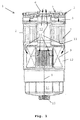
- Figure 1 shows the principle of a preferred embodiment in a simplified representation in cross section.
- the fuel filter 1 shows schematically a fuel filter 1 with a housing 2 , which is closed at its upper end with a cover 3 .
- the fuel filter 1 is constructed substantially rotationally symmetrical about a central axis 4 and designed substantially pot-shaped.
- a fuel inlet 5 and in the middle of a fuel outlet 6 is provided.
- a first filter stage 7 is arranged, wherein extending between the lid 3 and the first filter stage 7, a radial distribution area 8 .
- the first filter stage 7 is arranged as a wound insert (wound filter) concentric to the central axis 4 .
- Cellulose and / or glass fibers which are partly or completely impregnated such that the filter material has coalescence properties and has a hydrophilic effect are preferably used as the filter material for the wound filter.
- the impregnated portion of the fibers is between about 60% and 90%.
- a second filter stage 9 is arranged, wherein between the first filter stage 7 and the second filter stage, a, in the manner of an annular disc extending, radial collecting area 11 is located. Between the second filter stage 9 formed by a star filter insert and the housing wall, there remains an annular gap which adjoins the radial collecting area 11 , axial distribution area 12 and encloses the second filter stage 9 radially from the outside.
- the outer area of the star filter insert is its dirty side, the inside the clean side, with the top and bottom of the star filter insert are sealed against the dirty side.
- the filter material for the second filter stage 9 various materials can be used. Preferably, at least in part, a material such as cellulose or synthetic fibers or glass fibers or the like is used more.
- the clean side of the second filter stage 9 is connected to the fuel outlet 6 in the cover 3 via an outlet pipe 13 extending along the center axis 4 .
- a water outlet 15 is provided, which can be closed by a drain screw, not shown here or a controllable discharge valve.
- the advantage of the arrangement of a radially infiltrated star filter insert behind an axially flowing winding insert is that the flow cross section of the winding insert is limited by the housing diameter and the outer diameter of the outlet tube 13 , the axial extent of the star filter insert but varies within certain limits depending on the height of the housing can be.
- the fuel to be filtered passes through the fuel inlet 5 via the radial distribution region 8 in the winding insert of the first filter stage 7.
- the first filter stage 7 is substantially axially, ie, flows parallel to its longitudinal axis and the central axis 4 . Due to the hydrophilic properties of the first filter stage, the water droplets distributed extremely finely in the emulsion are at least partially collected and combined to form larger water droplets and droplets.
- the fuel exits the first filter stage 7 into the radial collecting area 11 , from which it passes into the axial distribution area 12 .
- the axial distribution region 12 of the fuel to be filtered is distributed to the filter surface of the second filter stage 9 and occurs radially from outside to inside through the second filter stage 9 through, in the outlet pipe 17 and via the fuel outlet 6 from the housing 2 . Secluded water runs due to gravity on the dirty side of the second filter stage 9 in the sump 14 .
- the arrows 16 indicate the respective flow direction of the fuel in the housing.
- the Invention can also be realized in other embodiments.
- a plurality of 3, 4, 5 or more filter stages be provided.
- a hydrophilic filter stages as view first filter stage and another, downstream located hydrophobic filter stage as the second.
- the "first" and the "second” filter level can be one or more more Filter stages be separated.
- several filter cartridges can too be summarized a filter stage.
- the invention not on the arrangement of a star filter insert as the second Filter stage downstream behind an axially traversed Wickelfilter limited as the first filter stage. Rather, you can suitable filter inserts from a variety of the expert known form of filter cartridges are selected. The same applies to the selection of filter materials.
Landscapes
- Engineering & Computer Science (AREA)
- Chemical & Material Sciences (AREA)
- Chemical Kinetics & Catalysis (AREA)
- Combustion & Propulsion (AREA)
- Mechanical Engineering (AREA)
- General Engineering & Computer Science (AREA)
- Filtering Materials (AREA)
Applications Claiming Priority (2)
| Application Number | Priority Date | Filing Date | Title |
|---|---|---|---|
| DE10360208 | 2003-12-20 | ||
| DE10360208A DE10360208A1 (de) | 2003-12-20 | 2003-12-20 | Zweistufiger Filter Kraftstofffilter |
Publications (4)
| Publication Number | Publication Date |
|---|---|
| EP1544452A2 true EP1544452A2 (fr) | 2005-06-22 |
| EP1544452A3 EP1544452A3 (fr) | 2010-04-07 |
| EP1544452B1 EP1544452B1 (fr) | 2011-08-17 |
| EP1544452B2 EP1544452B2 (fr) | 2018-02-21 |
Family
ID=34485561
Family Applications (1)
| Application Number | Title | Priority Date | Filing Date |
|---|---|---|---|
| EP04105333.1A Expired - Lifetime EP1544452B2 (fr) | 2003-12-20 | 2004-10-27 | Filtre à carburant à deux étages |
Country Status (3)
| Country | Link |
|---|---|
| EP (1) | EP1544452B2 (fr) |
| DE (1) | DE10360208A1 (fr) |
| ES (1) | ES2367990T3 (fr) |
Cited By (5)
| Publication number | Priority date | Publication date | Assignee | Title |
|---|---|---|---|---|
| WO2011101750A1 (fr) * | 2010-05-25 | 2011-08-25 | Ufi Innovation Center S.R.L. | Groupe filtrant amélioré pour moteurs à combustion interne |
| WO2014083394A1 (fr) * | 2012-11-30 | 2014-06-05 | Ufi Filters S.P.A. | Cartouche filtrante |
| US20140197090A1 (en) * | 2013-01-15 | 2014-07-17 | Parker-Hannifin Corporation | Multistage high capacity and depth coalescing media system |
| JP2017115858A (ja) * | 2015-12-22 | 2017-06-29 | 京三電機株式会社 | 水分離器、フィルタ、および燃料フィルタ装置 |
| WO2017110542A1 (fr) * | 2015-12-22 | 2017-06-29 | 京三電機株式会社 | Séparateur d'eau, filtre et dispositif de filtre à carburant |
Families Citing this family (2)
| Publication number | Priority date | Publication date | Assignee | Title |
|---|---|---|---|---|
| DE102015218185A1 (de) * | 2015-09-22 | 2017-03-23 | Mahle International Gmbh | Filtermedium |
| DE102016010778A1 (de) | 2016-09-08 | 2018-03-08 | Mann+Hummel Gmbh | Trennmodul, Wasserabscheidevorrichtung mit einem Trennmodul und Filtersystem mit einer Wasserabscheidevorrichtung |
Family Cites Families (7)
| Publication number | Priority date | Publication date | Assignee | Title |
|---|---|---|---|---|
| US3187895A (en) * | 1963-01-23 | 1965-06-08 | Pall Corp | Fuel-water separator |
| US3465883A (en) † | 1967-07-25 | 1969-09-09 | Wix Corp | Fuel-water separator and filter |
| US4253954A (en) † | 1979-07-02 | 1981-03-03 | Nelson Industries, Inc. | Two-stage spin-on separating device |
| US4372847A (en) * | 1980-06-23 | 1983-02-08 | Chicago Rawhide Manufacturing Company | Fuel filter assembly and cartridge |
| US5993675A (en) † | 1997-12-31 | 1999-11-30 | Hagerthy; Albert P. | Fuel-water separator for marine and diesel engines |
| DE10123190A1 (de) * | 2001-05-12 | 2002-11-14 | Mahle Filtersysteme Gmbh | Kraftstofffilter mit wasserabscheidenden Mitteln |
| CN1761509A (zh) † | 2003-03-21 | 2006-04-19 | 曼·胡默尔有限公司 | 燃料过滤系统 |
-
2003
- 2003-12-20 DE DE10360208A patent/DE10360208A1/de not_active Ceased
-
2004
- 2004-10-27 ES ES04105333T patent/ES2367990T3/es not_active Expired - Lifetime
- 2004-10-27 EP EP04105333.1A patent/EP1544452B2/fr not_active Expired - Lifetime
Cited By (8)
| Publication number | Priority date | Publication date | Assignee | Title |
|---|---|---|---|---|
| WO2011101750A1 (fr) * | 2010-05-25 | 2011-08-25 | Ufi Innovation Center S.R.L. | Groupe filtrant amélioré pour moteurs à combustion interne |
| ITRE20100041A1 (it) * | 2010-05-25 | 2011-11-26 | Ufi Innovation Ct Srl | Gruppo filtrante perfezionato per motori endotermici |
| CN102893015A (zh) * | 2010-05-25 | 2013-01-23 | Ufi发明中心有限公司 | 一种改进的内燃机过滤器组 |
| WO2014083394A1 (fr) * | 2012-11-30 | 2014-06-05 | Ufi Filters S.P.A. | Cartouche filtrante |
| US20140197090A1 (en) * | 2013-01-15 | 2014-07-17 | Parker-Hannifin Corporation | Multistage high capacity and depth coalescing media system |
| US9604167B2 (en) * | 2013-01-15 | 2017-03-28 | Parker-Hannifin Corporation | Multistage high capacity and depth coalescing media system |
| JP2017115858A (ja) * | 2015-12-22 | 2017-06-29 | 京三電機株式会社 | 水分離器、フィルタ、および燃料フィルタ装置 |
| WO2017110542A1 (fr) * | 2015-12-22 | 2017-06-29 | 京三電機株式会社 | Séparateur d'eau, filtre et dispositif de filtre à carburant |
Also Published As
| Publication number | Publication date |
|---|---|
| EP1544452B1 (fr) | 2011-08-17 |
| DE10360208A1 (de) | 2005-07-28 |
| EP1544452B2 (fr) | 2018-02-21 |
| ES2367990T3 (es) | 2011-11-11 |
| EP1544452A3 (fr) | 2010-04-07 |
Similar Documents
| Publication | Publication Date | Title |
|---|---|---|
| DE102014000903B4 (de) | Filterelement und Filtervorrichtung | |
| DE102010052329A1 (de) | Kraftstofffilter | |
| DE102011120647A1 (de) | Kraftstofffilter einer Brennkraftmaschine und Filterelement eines Kraftstofffilters | |
| DE60003202T2 (de) | Verfahren und filter zur filtrierung eines schlammes | |
| DE10123190A1 (de) | Kraftstofffilter mit wasserabscheidenden Mitteln | |
| DE112017002974T5 (de) | Koaleszer mit perforierter schicht | |
| WO2013079172A1 (fr) | Dispositif de filtration | |
| DE2126080B2 (de) | Rohrförmiges Trennelement zum Filtern und Abscheiden von Wasser und Feststoffen aus Kraftstoff | |
| DE102015003915A1 (de) | Abscheideelement einer Abscheidevorrichtung zur Abscheidung wenigstens eines fluiden Mediums aus einem zu behandelnden Fluid und Abscheidevorrichtung | |
| EP3423169B1 (fr) | Élément filtrant et filtre à carburant | |
| DE102016009487B4 (de) | Abscheideelement, Vorrichtung sowie Verfahren zur Abscheidung von Flüssigkeit aus Rohgas oder aus Rohgasgemisch einer Kraftmaschine oder eines Kompressors | |
| DE102016003994A1 (de) | Filterelement für das Filtern eines durch das Filterelement hindurchtretenden Fluids, Koaleszenzfilter, Druckluftfilteranlage, Verwendung eines Filterelements und Verfahren zum Herstellen eines Koaleszenzfilters | |
| EP1544452B1 (fr) | Filtre à carburant à deux étages | |
| DE102010044773A1 (de) | Kraftstofffilter zur Filterung von Kraftstoff | |
| DE4340024A1 (de) | Flüssigkeitsfilter für Kraftstoff | |
| DE102012219885B3 (de) | Flüssigkeitsfilter | |
| WO2017137335A1 (fr) | Corps de milieu séparateur destiné à être utilisé dans un séparateur | |
| EP3185983B1 (fr) | Moyen de filtrage terminal, utilisation et procédé de préparation | |
| DE69907726T2 (de) | Filterkartusche und verfahren zur filtration einer trübe | |
| DE3128748A1 (de) | Mikrofilter | |
| DE10353367A1 (de) | System zur Abscheidung von Partikeln und Wasser | |
| EP3695893B1 (fr) | Dispositif filtrant | |
| WO2019072547A1 (fr) | Filtre à fluide | |
| DE102023001703A1 (de) | Abscheidevorrichtung | |
| DE102023121510A1 (de) | Koaleszenzabscheidereinsatz, Koaleszenzabscheider sowie Verfahren zur Herstellung eines Koaleszenzabscheidereinsatzes |
Legal Events
| Date | Code | Title | Description |
|---|---|---|---|
| PUAI | Public reference made under article 153(3) epc to a published international application that has entered the european phase |
Free format text: ORIGINAL CODE: 0009012 |
|
| AK | Designated contracting states |
Kind code of ref document: A2 Designated state(s): AT BE BG CH CY CZ DE DK EE ES FI FR GB GR HU IE IT LI LU MC NL PL PT RO SE SI SK TR |
|
| AX | Request for extension of the european patent |
Extension state: AL HR LT LV MK |
|
| PUAL | Search report despatched |
Free format text: ORIGINAL CODE: 0009013 |
|
| AK | Designated contracting states |
Kind code of ref document: A3 Designated state(s): AT BE BG CH CY CZ DE DK EE ES FI FR GB GR HU IE IT LI LU MC NL PL PT RO SE SI SK TR |
|
| AX | Request for extension of the european patent |
Extension state: AL HR LT LV MK |
|
| 17P | Request for examination filed |
Effective date: 20101007 |
|
| AKX | Designation fees paid |
Designated state(s): DE ES FR IT |
|
| GRAP | Despatch of communication of intention to grant a patent |
Free format text: ORIGINAL CODE: EPIDOSNIGR1 |
|
| RIC1 | Information provided on ipc code assigned before grant |
Ipc: F02M 37/22 20060101AFI20110218BHEP |
|
| GRAS | Grant fee paid |
Free format text: ORIGINAL CODE: EPIDOSNIGR3 |
|
| GRAA | (expected) grant |
Free format text: ORIGINAL CODE: 0009210 |
|
| AK | Designated contracting states |
Kind code of ref document: B1 Designated state(s): DE ES FR IT |
|
| REG | Reference to a national code |
Ref country code: DE Ref legal event code: R096 Ref document number: 502004012796 Country of ref document: DE Effective date: 20111013 |
|
| REG | Reference to a national code |
Ref country code: ES Ref legal event code: FG2A Ref document number: 2367990 Country of ref document: ES Kind code of ref document: T3 Effective date: 20111111 |
|
| PLBI | Opposition filed |
Free format text: ORIGINAL CODE: 0009260 |
|
| PLAX | Notice of opposition and request to file observation + time limit sent |
Free format text: ORIGINAL CODE: EPIDOSNOBS2 |
|
| 26 | Opposition filed |
Opponent name: UFI FILTERS S.P.A. Effective date: 20120515 |
|
| REG | Reference to a national code |
Ref country code: DE Ref legal event code: R026 Ref document number: 502004012796 Country of ref document: DE Effective date: 20120515 |
|
| PLBB | Reply of patent proprietor to notice(s) of opposition received |
Free format text: ORIGINAL CODE: EPIDOSNOBS3 |
|
| PLAY | Examination report in opposition despatched + time limit |
Free format text: ORIGINAL CODE: EPIDOSNORE2 |
|
| PLAH | Information related to despatch of examination report in opposition + time limit modified |
Free format text: ORIGINAL CODE: EPIDOSCORE2 |
|
| REG | Reference to a national code |
Ref country code: FR Ref legal event code: PLFP Year of fee payment: 12 |
|
| PLBC | Reply to examination report in opposition received |
Free format text: ORIGINAL CODE: EPIDOSNORE3 |
|
| REG | Reference to a national code |
Ref country code: FR Ref legal event code: PLFP Year of fee payment: 13 |
|
| APAH | Appeal reference modified |
Free format text: ORIGINAL CODE: EPIDOSCREFNO |
|
| APBM | Appeal reference recorded |
Free format text: ORIGINAL CODE: EPIDOSNREFNO |
|
| APBP | Date of receipt of notice of appeal recorded |
Free format text: ORIGINAL CODE: EPIDOSNNOA2O |
|
| APBU | Appeal procedure closed |
Free format text: ORIGINAL CODE: EPIDOSNNOA9O |
|
| REG | Reference to a national code |
Ref country code: FR Ref legal event code: PLFP Year of fee payment: 14 |
|
| PUAH | Patent maintained in amended form |
Free format text: ORIGINAL CODE: 0009272 |
|
| STAA | Information on the status of an ep patent application or granted ep patent |
Free format text: STATUS: PATENT MAINTAINED AS AMENDED |
|
| 27A | Patent maintained in amended form |
Effective date: 20180221 |
|
| AK | Designated contracting states |
Kind code of ref document: B2 Designated state(s): DE ES FR IT |
|
| REG | Reference to a national code |
Ref country code: DE Ref legal event code: R102 Ref document number: 502004012796 Country of ref document: DE |
|
| PGFP | Annual fee paid to national office [announced via postgrant information from national office to epo] |
Ref country code: ES Payment date: 20171103 Year of fee payment: 14 |
|
| PG25 | Lapsed in a contracting state [announced via postgrant information from national office to epo] |
Ref country code: ES Free format text: LAPSE BECAUSE OF FAILURE TO SUBMIT A TRANSLATION OF THE DESCRIPTION OR TO PAY THE FEE WITHIN THE PRESCRIBED TIME-LIMIT Effective date: 20180221 |
|
| REG | Reference to a national code |
Ref country code: FR Ref legal event code: PLFP Year of fee payment: 15 |
|
| PGFP | Annual fee paid to national office [announced via postgrant information from national office to epo] |
Ref country code: FR Payment date: 20221020 Year of fee payment: 19 |
|
| PGFP | Annual fee paid to national office [announced via postgrant information from national office to epo] |
Ref country code: IT Payment date: 20221031 Year of fee payment: 19 Ref country code: DE Payment date: 20221215 Year of fee payment: 19 |
|
| REG | Reference to a national code |
Ref country code: DE Ref legal event code: R119 Ref document number: 502004012796 Country of ref document: DE |
|
| PG25 | Lapsed in a contracting state [announced via postgrant information from national office to epo] |
Ref country code: FR Free format text: LAPSE BECAUSE OF NON-PAYMENT OF DUE FEES Effective date: 20231031 Ref country code: DE Free format text: LAPSE BECAUSE OF NON-PAYMENT OF DUE FEES Effective date: 20240501 |
|
| PG25 | Lapsed in a contracting state [announced via postgrant information from national office to epo] |
Ref country code: IT Free format text: LAPSE BECAUSE OF NON-PAYMENT OF DUE FEES Effective date: 20231027 |
|
| PG25 | Lapsed in a contracting state [announced via postgrant information from national office to epo] |
Ref country code: IT Free format text: LAPSE BECAUSE OF NON-PAYMENT OF DUE FEES Effective date: 20231027 |