EP1544476B1 - Halterung für einen Wegaufnehmer für Zylinder - Google Patents
Halterung für einen Wegaufnehmer für Zylinder Download PDFInfo
- Publication number
- EP1544476B1 EP1544476B1 EP04024672A EP04024672A EP1544476B1 EP 1544476 B1 EP1544476 B1 EP 1544476B1 EP 04024672 A EP04024672 A EP 04024672A EP 04024672 A EP04024672 A EP 04024672A EP 1544476 B1 EP1544476 B1 EP 1544476B1
- Authority
- EP
- European Patent Office
- Prior art keywords
- cylinder body
- rod
- sensor mount
- mounting portion
- sensor
- Prior art date
- Legal status (The legal status is an assumption and is not a legal conclusion. Google has not performed a legal analysis and makes no representation as to the accuracy of the status listed.)
- Expired - Lifetime
Links
- 210000004907 gland Anatomy 0.000 claims abstract description 83
- 238000000034 method Methods 0.000 claims abstract description 10
- 230000008878 coupling Effects 0.000 claims abstract description 7
- 238000010168 coupling process Methods 0.000 claims abstract description 7
- 238000005859 coupling reaction Methods 0.000 claims abstract description 7
- 241000180579 Arca Species 0.000 claims 1
- 238000007789 sealing Methods 0.000 description 3
- 230000013011 mating Effects 0.000 description 2
- 238000012986 modification Methods 0.000 description 2
- 230000004048 modification Effects 0.000 description 2
- 238000010079 rubber tapping Methods 0.000 description 2
- 239000000126 substance Substances 0.000 description 2
- 230000000712 assembly Effects 0.000 description 1
- 238000000429 assembly Methods 0.000 description 1
- 230000001419 dependent effect Effects 0.000 description 1
- 238000003780 insertion Methods 0.000 description 1
- 230000037431 insertion Effects 0.000 description 1
- 238000004519 manufacturing process Methods 0.000 description 1
- 239000000463 material Substances 0.000 description 1
Images


Classifications
-
- F—MECHANICAL ENGINEERING; LIGHTING; HEATING; WEAPONS; BLASTING
- F15—FLUID-PRESSURE ACTUATORS; HYDRAULICS OR PNEUMATICS IN GENERAL
- F15B—SYSTEMS ACTING BY MEANS OF FLUIDS IN GENERAL; FLUID-PRESSURE ACTUATORS, e.g. SERVOMOTORS; DETAILS OF FLUID-PRESSURE SYSTEMS, NOT OTHERWISE PROVIDED FOR
- F15B15/00—Fluid-actuated devices for displacing a member from one position to another; Gearing associated therewith
- F15B15/20—Other details, e.g. assembly with regulating devices
- F15B15/28—Means for indicating the position, e.g. end of stroke
- F15B15/2815—Position sensing, i.e. means for continuous measurement of position, e.g. LVDT
-
- F—MECHANICAL ENGINEERING; LIGHTING; HEATING; WEAPONS; BLASTING
- F15—FLUID-PRESSURE ACTUATORS; HYDRAULICS OR PNEUMATICS IN GENERAL
- F15B—SYSTEMS ACTING BY MEANS OF FLUIDS IN GENERAL; FLUID-PRESSURE ACTUATORS, e.g. SERVOMOTORS; DETAILS OF FLUID-PRESSURE SYSTEMS, NOT OTHERWISE PROVIDED FOR
- F15B15/00—Fluid-actuated devices for displacing a member from one position to another; Gearing associated therewith
- F15B15/08—Characterised by the construction of the motor unit
- F15B15/14—Characterised by the construction of the motor unit of the straight-cylinder type
- F15B15/1423—Component parts; Constructional details
- F15B15/1433—End caps
-
- F—MECHANICAL ENGINEERING; LIGHTING; HEATING; WEAPONS; BLASTING
- F15—FLUID-PRESSURE ACTUATORS; HYDRAULICS OR PNEUMATICS IN GENERAL
- F15B—SYSTEMS ACTING BY MEANS OF FLUIDS IN GENERAL; FLUID-PRESSURE ACTUATORS, e.g. SERVOMOTORS; DETAILS OF FLUID-PRESSURE SYSTEMS, NOT OTHERWISE PROVIDED FOR
- F15B15/00—Fluid-actuated devices for displacing a member from one position to another; Gearing associated therewith
- F15B15/20—Other details, e.g. assembly with regulating devices
- F15B15/28—Means for indicating the position, e.g. end of stroke
- F15B15/2892—Means for indicating the position, e.g. end of stroke characterised by the attachment means
Definitions
- the present invention relates generally to a mount for a position sensor and, more particularly, to a cylinder assembly with a position sensor mounted thereto.
- Expansible chamber hydraulic cylinders having moveable piston-and-rod assemblies therein are widely used on industrial, earthmoving, and material handling machines and vehicles. It may be advantageous for such a machine or vehicle to include an automatic control system for automatically controlling the extension or retraction of a piston-and-rod assembly within a hydraulic cylinder so that partially or totally automatic work operations may be performed.
- a position sensor may be used to determine the position of the piston-and-rod assembly within the cylinder.
- One challenge with using such a position sensor is creating a robust, accurate, and affordable mount and mounting method for coupling the position sensor with the hydraulic cylinder.
- U.S. Patent No. 5,455,509 issued to Semura et al. , discloses a device for mounting a position-detecting sensor to a hydraulic cylinder.
- Semura discloses a piston rod with a magnetic scale formed on the outer surface thereof and a magnetic sensor mounted on a cylinder head proximate the magnetic scale for detecting the magnetic scale and determining the position of the piston rod.
- the sensor is mounted on a block, and the block is mounted directly to the head of the cylinder by a plurality of bolts.
- DE 100 45 874 A1 discloses a cylinder assembly including a cylinder, a sensor and a rod member slidably received within the sensor, wherein the sensor is connected to the cylinder via clips.
- DE 100 49 505 A1 discloses a cylinder assembly including a cylinder, a sensor and a rod member slidably received within the sensor wherein the sensor is connected to the cylinder via clips.
- Prior sensor-mounting devices and methods for cylinder position sensors may provide complicated assembly operations or may unduly stress components of a cylinder assembly.
- a position sensor mount is affixed directly to the head or gland of a cylinder
- alignment of the sensor mount (and sensor) with a pattern or detectable feature on the rod may be affected by the alignment (or misalignment) of the head or gland with a detectable feature on the rod.
- bolting or otherwise attaching a sensor mount directly to the head or gland of a cylinder may complicate the required corresponding design or structure of the head or gland, thereby increasing production costs of the gland.
- attachment of a sensor mount directly to an existing gland may not be feasible or possible, for example due to the existing configuration of the gland or the condition of the gland.
- the present invention is directed at overcoming one or more problems or disadvantages associated with prior sensor-mounting devices and methods.
- a cylinder assembly as set forth in claim 1 and a method for determining the position of a rod slidably arranged within a longitudinal cylinder chamber of a cylinder body is provided.
- Preferred embodiments are disclosed in the dependent claims.
- a cylinder assembly may include a cylinder body, a gland member, a sensor mount, a rod member, and a position sensor.
- the cylinder body may have a longitudinal cylinder chamber therein, a gland opening at an end of the cylinder body, and a first mounting portion disposed on the cylinder body.
- the gland member may have a rod opening therein and may be disposed within the gland opening of the cylinder body.
- the sensor mount may have a rod opening therein and may be disposed proximate the end of the cylinder body and adjacent the gland member and may have a second mounting portion disposed on the sensor mount.
- the rod member may be slidably arranged within the rod openings of the sensor mount and the gland member and may extend into the longitudinal cylinder chamber of the cylinder body.
- the position sensor may be attached to the sensor mount.
- the sensor mount may be attached to the cylinder body via a coupling engagement between the second mounting portion of the sensor mount and the first mounting portion of the cylinder body.
- a cylinder assembly may include a cylinder body, a gland member, a sensor mount, a rod member, and a position sensor.
- the cylinder body may have a longitudinal cylinder chamber therein, a gland opening at an end of the cylinder body, and a first mounting portion disposed on the cylinder body.
- the gland member may have a rod opening therein and may be disposed within the gland opening of the cylinder body.
- the sensor mount may have a rod opening therein and may be disposed proximate the end of the cylinder body and adjacent the gland member and may have a second mounting portion disposed thereon.
- the rod member may be slidably arranged within the rod openings of the sensor mount and the gland member and may extend into the longitudinal cylinder chamber of the cylinder body.
- the rod member may have one or more detectable features disposed longitudinally along the length of the rod.
- the position sensor may be attached to the sensor mount and may be operable to detect the detectable features.
- the second mounting portion of the sensor mount may be urged toward the first mounting portion of the cylinder body to hold the sensor in a substantially predetermined orientation relative the path of the one or more detectable features.
- a method may be provided for determining the position of a rod slidably arranged within a longitudinal cylinder chamber of a cylinder body having a gland member disposed within one end of the cylinder body, the gland member having a rod opening therein for slidably receiving the rod.
- the method may include providing a first mounting portion on the cylinder body; providing a sensor mount having a rod opening therein, a second mounting portion thereon, and a position sensor attached thereto; providing one or more detectable features along the length of the rod; aligning the position sensor with a path of the one or more detectable features; mounting the sensor mount to the end of the cylinder body and adjacent the gland member by fastening together the second mounting portion of the sensor mount and the first mounting portion of the cylinder body; moving the rod within the rod openings of the gland member and the sensor mount; and operating the sensor to detect the detectable features of the rod and to generate a signal as a function of the detectable features, the signal being indicative of the position of the rod.
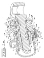
- an exemplary embodiment of the present invention includes a cylinder assembly 10 having a cylinder body 14, a gland member 18, a sensor mount 22, a rod member 26, and a position sensor 30.
- the cylinder body 14 provides a longitudinal cylinder chamber 34 therein for receipt of the rod member 26.
- the cylinder body 14 includes a radially outer wall 14a and a radially inner wall 14b.
- a gland opening 38 is provided at one end 42 of the cylinder body 14 and is configured and arranged for receipt of the gland member 18. Threads 46a may be provided on the inner wall 14b within the gland opening 38 for engagement with threads 46b on the gland member 18.
- a first mounting portion 50 may be provided on the outer wall 14a of the cylinder body 14.
- the first mounting portion 50 is a flange member extending radially outward from the cylinder body 14 and may be welded to the cylinder body 14.
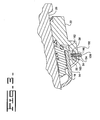
- the flange member 50 has a first opening 54 therein, the first opening 54 being arranged in a substantially longitudinal orientation.
- the first opening 54 is arranged in a substantially radial orientation.
- the first opening 54 may have a threaded section 58 therein.
- one, two, three, four, or more first mounting portions 50 may be provided on the cylinder body 14.
- the embodiment shown in FIGS. 1A and 2 includes three first mounting portions 50, but alternative embodiments may include less or more (for example four) mounting portions 50, depending for example on strength or configuration requirements.
- a generally cylindrical gland member 18 may be disposed within the gland opening 38 of the cylinder body 14 and may be sealingly engaged with the inner wall 14b of the cylinder body 14.
- the gland member 18 has a rod opening therein, such as a longitudinal throughbore 62, configured for slidable receipt of the rod member 26.
- a radially outer surface 66 of the gland member 18 may provide threads 46b for engaging the threads 46a of the inner wall 14b of the cylinder body 14.
- a seal groove 70 may also be provided along the outer surface of the gland member 18, and a seal 74 may be provided therein for ensuring a sealing engagement between the gland member 18 and the inner wall 14b of the cylinder body 14.
- Grooves 78, 82, 86 may be provided along an internal wall 94 of the gland member 18 for seating a wear ring 98, a buffer seal 102, and a rod seal 106, respectively.
- a groove 90 having a wiper seal 110 therein may be provided.
- the gland member 18 may have a flange portion 114 disposed outside of the gland opening 38 of the cylinder body 14 and extending radially outward, for example beyond the inner and outer walls 14b, 14a of the cylinder body 14.
- the sensor mount 22 shown in FIG. 1A is disposed proximate the end 42 of the cylinder body 14 and adjacent the gland member 18.
- the sensor mount 22 has a rod opening therein, such as a longitudinal throughbore 118, for slidably receiving the rod member 26. It should be appreciated that the sensor mount 22 need not extend completely around the rod member 26.
- a sensor bore 122 may be arranged radially within the sensor mount 22 and may intersect the longitudinal throughbore 118.
- a sensor counterbore 126 generally in alignment with the sensor bore 122 may be formed in the sensor mount 22. Grooves 130, 134 may be provided within the sensor mount 22 for seating wiper seals 138, 142 outboard of the sensor bore 122 and sensor 30 and inboard of the sensor bore 122 and sensor 30, respectively.
- the wiper seals 138 and 142 may be configured to engage the outer surface of the rod 26 to keep the area along the rod 26 between the wiper seals 138 and 142 (or 110) free from debris or other substances that may interfere with operation of the sensor 30. It should be appreciated that an alternative embodiment may exclude both of the seals 142 ( FIG. 1A ), 110 ( FIG. 1B ).
- the sensor mount 22 provides a second mounting portion 146 thereon.
- the second mounting portion 146 is formed within a flange portion 150 of the sensor mount 22 that extends radially outward from the mount 22 and around the circumference of the mount 22.
- the second mounting portion 146 may include a second opening 154 therein, the second opening 154 being arranged in a substantially longitudinal orientation.
- the flange portion 150 and the second mounting portion 146 of the sensor mount 22 may extend over the first mounting portion 50 so that the first mounting portion 50 is seated within the flange portion 150.
- the second opening 154 may be arranged in a substantially radial orientation.
- the second mounting portion 146 of the sensor mount 22 is aligned with the first mounting portion 50 of the cylinder body 14, and the second opening 154 is aligned with the first opening 54.
- the mounting portions 50, 146 may be attached together via a coupling engagement.
- a mounting pin 158 such as a bolt, may be arranged within the second opening 154 and the first opening 54. Threads 163 on the mounting pin 158 may engage threads 58 in the first opening 54, and as the mounting pin 158 is rotated relative the first and second openings 54, 154, the second mounting portion 146 is urged toward and coupled to the first mounting portion 50, and the sensor mount 22 may be urged toward and coupled to the cylinder body 14.
- the mounting pin 158 may extend completely through the first opening 54 of the embodiment of FIG. 1 to engage a nut on the rear side of the first opening 54, and the mounting pin 158 and nut may be tightened together to urge and couple together the first and second mounting portions 50, 146 and the cylinder body 14 and the sensor mount 22.
- the sensor mount 22 may have a counterbore 162 therein.
- the counterbore 162 may be sized to receive the gland member 18 and the end 42 of the cylinder body 14.
- the flange portion 114 of the gland member 18 may be seated within the counterbore 162 of the sensor mount; a seal groove 166 may be provided within a mating, radially-arranged face of the gland member 18 (or within a radially-arranged face of the sensor mount 22); and a seal 170 may be seated within the groove 166 to provide a sealed engagement between the radially-arranged face of the gland member 18 and a radially-arranged face of the sensor mount 22.
- the sealed engagement between the gland member 18 and the sensor mount 22 may prevent or inhibit debris or other substances from entering the area between the wiper seals 138, 142 and affecting the performance of the sensor 30.
- the rod member 26 is slidably arranged within the throughbores 118, 62 of the sensor mount 22 and the gland member 18 and extends into the longitudinal cylinder chamber 34 of the cylinder body 14, where the rod member 26 may be operably connected with a piston (not shown), as is known in the art, to form a piston-and-rod assembly.
- One or more detectable features 174 such as barcode markings, may be disposed in a predetermined orientation along the length of the rod 26. It should be appreciated that the features 174 are shown in FIG. 1A , for explanatory purposes, as being inboard of the gland member 18, and that the features 174 may extend along the full length of the rod 26 in practice.
- a position sensor 30 is connected to the sensor mount 22 and is arranged in alignment with the path of the detectable features 174 of the rod 26.
- the sensor 30 may be operable to detect the one or more detectable features 174 and responsively generate a signal indicative of the position of the rod 26 as a function of the one or more detectable features 174.
- the senor 30 is housed within a radially arranged bore 178 of a sensor subhousing 182, for example via a press-fit or set screw configuration.
- the subhousing 182 includes a flange 186, which is seated within the counterbore 126 of the sensor mount 22, and the subhousing 182 is attached to the sensor mount 22 via one or more screws 190 or the like.
- the subhousing 182 includes a connector wall 194 that may protect the sensor 30 while providing a connecting surface for attaching a connector (not shown) to the sensor 30.
- a mating connector having an outer diameter slightly larger (or slightly smaller) than that of the connector wall 194 may be coupled with the connector wall 194 while engaging electrical contacts (not shown) on the sensor 30.
- the subhousing may further include a counterbore 198 wherein the sensor 30 may be seated during assembly.
- a groove 204 may be provided in the sensor bore 122 for seating a seal 208, such as an O-ring. The seal 208 may ensure a sealed engagement between the outer circumference of the sensor 30 and the sensor bore 122 to prevent or inhibit debris from entering the area between the sensor 30 and the rod member 26.
- the present invention provides an affordable and robust sensor mount operable to accurately mount a position sensor to a hydraulic cylinder.
- the cylinder assembly 10 of FIG. 1A may be assembled by placing the rod member 26 through the throughbores 118, 62 of the sensor mount 22 and the gland member 18, inserting the rod member 26 into the longitudinal cylinder chamber 34 of the cylinder body 14, and attaching the rod member 26 to a piston (not shown).
- the gland member 18 may be threaded into the gland opening 38 and cylinder chamber 34 of the cylinder body 14 (via rotation of the gland member 18 relative the cylinder body 14), thereby sealing the longitudinal cylinder chamber 34 of the cylinder body 14.
- the sensor mount 22 may be attached to the end 42 of the cylinder body 14 and adjacent the gland member 18 via the mounting pin 158 and the first and second mounting portions 50, 146, as described above, to form a coupling engagement between the first and second mounting portions 50, 146.
- the gland member 18 may be prevented or at least inhibited by the sensor mount 22 from rotating out of, or otherwise becoming unseated from, the gland opening 38 of the cylinder body 14.
- the sensor mount 22 may provide a locking function by holding the gland member 18 in sealing engagement with the cylinder body 14.
- the cylinder assembly 10 may be enabled to withstand higher operating pressures within the cylinder body 14.
- the path of the detectable features 174 is arranged in a substantially predetermined orientation on the rod member 26; the rod member 26 is arranged in a substantially predetermined rotational orientation relative the cylinder body 14 and the first mounting portion 54 (for example, if the cylinder body 14 and the rod member 26 are each fixedly attached to components of a work machine); the sensor 30 is arranged in a predetermined orientation relative the sensor mount 22 and the second mounting portion 154, for example via the sensor bore 122 and the sensor subhousing 182; and the first and second mounting portions 50, 146 are coupled together in a substantially predetermined orientation relative to each other, for example via alignment of the first and second openings 54, 154 and insertion of the mounting pin 158 therethrough.
- the position sensor 30 will be substantially aligned with a path of the detectable features 174, and the position sensor 30 will function properly without regard to the rotational configuration of the gland member 18 relative the cylinder body 14 or the rod member 26.
- the gland member 18 may be tightened relative the cylinder body 14 (via threads 46a, 46b for example) to a desired degree without regard to the gland member's final orientation relative the detectable features 174 of the rod 26.
- the disclosed sensor mount 22 may be added to an existing cylinder assembly without substantial modification of the cylinder assembly's components.
- the sensor mount 22 may be added to the assembly without tapping holes in the existing gland member or head of the assembly.
- one or more first mounting portions 50 may be welded or otherwise affixed to a cylinder body 14 to facilitate attachment of the sensor mount 22 to the cylinder body 14.
Landscapes
- Engineering & Computer Science (AREA)
- Physics & Mathematics (AREA)
- Fluid Mechanics (AREA)
- Mechanical Engineering (AREA)
- General Engineering & Computer Science (AREA)
- Actuator (AREA)
- Length Measuring Devices With Unspecified Measuring Means (AREA)
- Measurement Of Length, Angles, Or The Like Using Electric Or Magnetic Means (AREA)
- Superconductors And Manufacturing Methods Therefor (AREA)
- Diaphragms For Electromechanical Transducers (AREA)
- Measurement Of Velocity Or Position Using Acoustic Or Ultrasonic Waves (AREA)
- Length Measuring Devices Characterised By Use Of Acoustic Means (AREA)
Claims (8)
- Eine Zylinderanordnung (10), die Folgendes aufweist:einen Zylinderkörper (14) mit einer sich in Längsrichtung darin erstreckenden Zylinderkammer (34), einer Dichtungsöffnung (38) an einem Ende des Zylinderkörpers und mit einem ersten Befestigungsteil (50) angeordnet am Zylinderkörper;ein Gland- bzw. Dichtglied (18) mit einer Stangenöffnung (62) darinnen, wobei das Dichtglied innerhalb der Dichtöffnung des Zylinderkörpers angeordnet ist;eine Sensorbefestigung (22) mit einer Stangenöffnung (118) darinnen, wobei die Sensorbefestigung nahe dem Ende des Zylinderkörpers angeordnet ist und benachbart zum Dichtglied und mit einem zweiten Befestigungsteil (246) angeordnet an der Sensorbefestigung;ein Stangenglied (26) gleitbar angeordnet innerhalb der Stangenöffnungen der Sensorbefestigung und des Dichtgliedes und sich in die sich in Längsrichtung verlaufende Zylinderkammer des Zylinderkörpers erstreckend;einen Positionssensor (30) angebracht an der Sensorbefestigung;wobei die Sensorbefestigung am Zylinderkörper befestigt ist und zwar über einen Kupplungseingriff zwischen dem zweiten Befestigungsteil der Sensorbefestigung und dem ersten Befestigungsteil des Zylinderkörpers, dadurch gekennzeichnet, dass der erste Befestigungsteil eine erste Öffnung (54) darinnen besitzt; dass der zweite Befestigungsteil eine zweite Öffnung (154) darin besitzt, und dass die Zylinderanordnung einen Befestigungsstift (158) aufweist und zwar angeordnet innerhalb der ersten und zweiten Öffnungen.
- Zylinderanordnung nach Anspruch 1, wobei:der Zylinderkörper eine sich radial erstreckende Innenwand (14b) aufweist;das Dichtglied eine radial verlaufende Außenoberfläche (66) besitzt;die radial verlaufende Außenoberfläche des Dichtglieds in Eingriff steht mit der radial verlaufenden Innenwand des Zylinderkörpers; unddie Sensorbefestigung gegen das Dichtglied gedrückt wird, und zwar über den Kupplungseingriff zwischen dem zweiten Befestigungsteil der Sensorbefestigung und dem ersten Befestigungsteil des Zylinderkörpers.
- Zylinderanordnung nach Anspruch 2, wobei:die radial verlaufende Innenwand des Zylinderkörpers eine erste mit Gewinde versehene Fläche (46) darauf aufweist;die radial verlaufende Außenoberfläche des Dichtglieds eine zweite mit Gewinde versehene Fläche (46b) darauf aufweist;das Dichtglied mit dem Zylinderkörper in Eingriff steht, und zwar über die ersten und zweiten mit Gewinde versehenen Flächen; und wobeidie Sensorbefestigung konfiguriert und angeordnet ist, um zu verhindern oder zu sperren, dass sich das Dichtglied in mindestens eine Richtung relativ zum Zylinderkörper verdreht.
- Zylinderanordnung nach Anspruch 1, wobei:die Stange ein oder mehrere detektierbare Merkmale (174) aufweisen, und zwar angeordnet in Längsrichtung entlang der Länge der Stange; unddie Stange bezüglich des Zylinderkörpers derart angeordnet ist, dass ein Pfad von einem oder mehreren der detektierbaren Merkmale in einer im Wesentlichen vorbestimmten Orientierung relativ zum ersten Befestigungsteil angeordnet ist.
- Zylinderanordnung nach Anspruch 1, wobei:die Stange eine oder mehrere detektierbare Merkmale (174) darauf besitzt; wobeider Positionssensor in einer vorbestimmten Orientierung bezüglich eines Pfades angeordnet ist, und zwar von einem oder mehreren der detektierbaren Merkmale und wobei der Positionssensor betätigbar ist, um eines oder mehrere der detektierbaren Merkmale zu detektieren und um ein Signal zu erzeugen, welches eine Anzeige liefert für die Position der Stange als eine Funktion von dem einen oder den mehreren detektierbaren Merkmalen.
- Zylinderanordnung nach Anspruch 1 mit einem Dichtglied (170) gepresst zwischen einer radial angeordneten Stirnfläche der Sensorbefestigung und einer radial angeordnete Stirnfläche des Gland- oder Dichtgliedes.
- Verfahren zur Bestimmung der Position einer Stange (26) gleitbar angeordnet innerhalb einer Zylinderlängskammer (34) eines Zylinderkörpers (14) mit einem Dichtglied (18) angeordnet innerhalb eines Endes des Zylinderkörpers, wobei das Dichtglied eine Stangenöffnung (62) aufweist und zwar zur Gleitaufnahme der Stangen, wobei das Verfahren Folgendes vorsieht:Vorsehen eines ersten Befestigungsteils (50) am Zylinderkörper;Vorsehen einer Sensorbefestigung (22) mit einer Stangenöffnung (118) darin, einem zweiten Befestigungsteil (146) darauf und einem Positionssensor (30) angebracht daran;Vorsehen von einem oder mehreren detektierbaren Merkmalen (174) entlang der Länge der Stange;Ausrichten des Positionssensors mit einem Pfad des einen detektierbaren Merkmals oder der mehreren detektierbaren Merkmale;Befestigung der Sensorbefestigung am Ende des Zylinderkörpers und benachbart zu dem Dichtglied durch miteinander Befestigen des zweiten Befestigungsteils der Sensorbefestigung und des ersten Befestigungsteils des Zylinderkörpers;Bewegen der Stange innerhalb der Stangenöffnungen des Dichtgliedes und der Sensorbefestigung;Betätigung des Sensors zum Detektieren der detektierbaren Merkmale der Stange und zur Erzeugung eines Signals als eine Funktion der detektierbaren Merkmale, wobei das Signal eine Anzeige für die Position der Stange liefert; undAusrichten einer ersten Öffnung (54) in dem ersten Befestigungsteil des Zylinderkörpers mit einer zweiten Öffnung (154) in dem zweiten Befestigungsteil der Sensorbefestigung; und Einsetzen eines Befestigungsstiftes (158) durch die ersten und zweiten Öffnungen.
- Verfahren nach Anspruch 7, wobei Folgendes vorgesehen ist:Drücken der Sensorbefestigung gegen das Dichtglied zum Halten des Dichtglieds in Position bezüglich des Zylinderkörpers.
Applications Claiming Priority (2)
| Application Number | Priority Date | Filing Date | Title |
|---|---|---|---|
| US742531 | 2003-12-19 | ||
| US10/742,531 US7162947B2 (en) | 2003-12-19 | 2003-12-19 | Mount for cylinder position sensor |
Publications (3)
| Publication Number | Publication Date |
|---|---|
| EP1544476A2 EP1544476A2 (de) | 2005-06-22 |
| EP1544476A3 EP1544476A3 (de) | 2005-09-21 |
| EP1544476B1 true EP1544476B1 (de) | 2008-04-02 |
Family
ID=34523256
Family Applications (1)
| Application Number | Title | Priority Date | Filing Date |
|---|---|---|---|
| EP04024672A Expired - Lifetime EP1544476B1 (de) | 2003-12-19 | 2004-10-15 | Halterung für einen Wegaufnehmer für Zylinder |
Country Status (4)
| Country | Link |
|---|---|
| US (1) | US7162947B2 (de) |
| EP (1) | EP1544476B1 (de) |
| AT (1) | ATE391240T1 (de) |
| DE (1) | DE602004012828T2 (de) |
Families Citing this family (8)
| Publication number | Priority date | Publication date | Assignee | Title |
|---|---|---|---|---|
| US7762037B2 (en) | 2005-11-18 | 2010-07-27 | General Electric Company | Segment for a tower of a wind energy turbine and method for arranging operating components of a wind energy turbine in a tower thereof |
| DE102005059984A1 (de) * | 2005-12-13 | 2007-06-14 | Zf Friedrichshafen Ag | Sensoreinrichtung für ein Kolben-Zylinderaggregat |
| CN101473186B (zh) * | 2006-06-16 | 2011-02-09 | 株式会社小松制作所 | 汽缸的冲程位置测量装置 |
| US8240240B2 (en) | 2008-10-31 | 2012-08-14 | Cnh America Llc | Cylinder position sensor |
| US9422950B2 (en) * | 2011-02-18 | 2016-08-23 | Parker-Hannifin Corporation | Floating optical sensor mount |
| DE102018123184A1 (de) * | 2018-09-20 | 2020-03-26 | Liebherr-Components Kirchdorf GmbH | Kolben-Zylinder-Einheit für eine Arbeitsmaschine |
| US20230139055A1 (en) * | 2021-10-29 | 2023-05-04 | Caterpillar Inc. | Hydraulic cylinder with a side load sensor retention pin |
| US12516686B2 (en) | 2023-06-26 | 2026-01-06 | Woodward, Inc. | Dual-parallel actuator piston interface |
Family Cites Families (15)
| Publication number | Priority date | Publication date | Assignee | Title |
|---|---|---|---|---|
| US3750537A (en) * | 1971-06-28 | 1973-08-07 | Caterpillar Tractor Co | Hydraulic cylinder with self-locking end cap |
| US3777627A (en) * | 1972-04-07 | 1973-12-11 | Caterpillar Tractor Co | End cap locking means for hydraulic cylinders and method |
| US3956973A (en) * | 1972-07-11 | 1976-05-18 | Basic Aluminum Castings Company | Die casting machine with piston positioning control |
| US4982652A (en) * | 1989-05-19 | 1991-01-08 | Blatt John A | Fluid operated actuator with recessed position sensor and recessed end cap fastener |
| US5455509A (en) * | 1990-10-26 | 1995-10-03 | Kabushiki Kaisha Komatsu Seisakusho | Device for mounting position detecting sensor |
| US5182980A (en) * | 1992-02-05 | 1993-02-02 | Caterpillar Inc. | Hydraulic cylinder position sensor mounting apparatus |
| FI91325C (fi) * | 1992-04-07 | 1994-06-10 | Partek Cargotec Oy | Paikka-asteikko ja optinen lukuanturi tämän paikka-asteikon lukemiseksi |
| US5325063A (en) * | 1992-05-11 | 1994-06-28 | Caterpillar Inc. | Linear position sensor with means to eliminate spurians harmonic detections |
| US5477771A (en) * | 1993-08-10 | 1995-12-26 | Black; Philip B. | Hydraulic cylinder assembly |
| CN1216822A (zh) * | 1997-10-31 | 1999-05-19 | 沃尔沃建造设备(韩)有限公司 | 用于行程传感缸的绝对位置检测方法 |
| US6147342A (en) * | 1998-06-02 | 2000-11-14 | Caterpillar Inc. | Encoding system for determining the position of a cylinder rod along a path of movement |
| US6666784B1 (en) | 1999-10-06 | 2003-12-23 | Ntn Corporation | Piston rod piston detector, autotensioner and belt tension adjuster |
| DE10045874A1 (de) | 2000-09-14 | 2002-03-28 | Continental Teves Ag & Co Ohg | Kraftfahrzeugsensorvorrichtung |
| US6484620B2 (en) * | 2000-12-28 | 2002-11-26 | Case Corporation | Laser based reflective beam cylinder sensor |
| US6834574B2 (en) * | 2002-01-04 | 2004-12-28 | Parker-Hannifin Corporation | Cylinder with optical position sensing device and method |
-
2003
- 2003-12-19 US US10/742,531 patent/US7162947B2/en not_active Expired - Fee Related
-
2004
- 2004-10-15 DE DE602004012828T patent/DE602004012828T2/de not_active Expired - Lifetime
- 2004-10-15 AT AT04024672T patent/ATE391240T1/de not_active IP Right Cessation
- 2004-10-15 EP EP04024672A patent/EP1544476B1/de not_active Expired - Lifetime
Also Published As
| Publication number | Publication date |
|---|---|
| EP1544476A3 (de) | 2005-09-21 |
| DE602004012828T2 (de) | 2009-04-16 |
| US20050132878A1 (en) | 2005-06-23 |
| US7162947B2 (en) | 2007-01-16 |
| EP1544476A2 (de) | 2005-06-22 |
| ATE391240T1 (de) | 2008-04-15 |
| DE602004012828D1 (de) | 2008-05-15 |
Similar Documents
| Publication | Publication Date | Title |
|---|---|---|
| US7051639B2 (en) | Mounting apparatus and method for cylinder position sensor | |
| US7023199B2 (en) | Position sensing cylinder cap for ease of service and assembly | |
| EP1676032B1 (de) | Verfahren und vorrichtung für hubpositionssensor für hydraulikzylinder | |
| US6417768B2 (en) | Method of assembling a monitor on a brake actuator | |
| EP1217220A2 (de) | Fluidzylinder mit integriertem Positionsensor | |
| EP1544476B1 (de) | Halterung für einen Wegaufnehmer für Zylinder | |
| US4982652A (en) | Fluid operated actuator with recessed position sensor and recessed end cap fastener | |
| EP2182222B1 (de) | Einstellbarer Zylinderpositionssensor | |
| CN1205400A (zh) | 流体压力缸的传感器安装装置 | |
| US6427992B1 (en) | Clamping cylinder actuator | |
| US20250207616A1 (en) | Piston-cylinder unit | |
| CN1330884C (zh) | 带有双向安装机构的流体压力机器 | |
| US12590595B2 (en) | Working cylinder | |
| CN216478144U (zh) | 一种具有活塞杆位移检测功能的液压油缸 | |
| CN210423237U (zh) | 内置位移传感器的油缸和具有其的工程机械 | |
| US11067105B1 (en) | Flange mount cylinder sensor | |
| US20230139055A1 (en) | Hydraulic cylinder with a side load sensor retention pin | |
| KR102623821B1 (ko) | 트랜스미션의 셀렉터 로드를 작동하기 위한 설정 장치 | |
| JPH08219115A (ja) | シリンダ | |
| US12535090B2 (en) | Piston-cylinder unit, set comprising a piston-cylinder unit and a group of piston-cylinder units | |
| JP2001113432A (ja) | クランプシリンダ | |
| NO344877B1 (no) | Leddbolt forsynt med utstyr for registrering av belastning | |
| JP2001107914A (ja) | クランプシリンダ | |
| HK40000434A (en) | Setting device for actuating a selector rod of a transmission |
Legal Events
| Date | Code | Title | Description |
|---|---|---|---|
| PUAI | Public reference made under article 153(3) epc to a published international application that has entered the european phase |
Free format text: ORIGINAL CODE: 0009012 |
|
| AK | Designated contracting states |
Kind code of ref document: A2 Designated state(s): AT BE BG CH CY CZ DE DK EE ES FI FR GB GR HU IE IT LI LU MC NL PL PT RO SE SI SK TR |
|
| AX | Request for extension of the european patent |
Extension state: AL HR LT LV MK |
|
| PUAL | Search report despatched |
Free format text: ORIGINAL CODE: 0009013 |
|
| AK | Designated contracting states |
Kind code of ref document: A3 Designated state(s): AT BE BG CH CY CZ DE DK EE ES FI FR GB GR HU IE IT LI LU MC NL PL PT RO SE SI SK TR |
|
| AX | Request for extension of the european patent |
Extension state: AL HR LT LV MK |
|
| RIC1 | Information provided on ipc code assigned before grant |
Ipc: 7F 15B 15/28 A Ipc: 7F 15B 15/14 B |
|
| 17P | Request for examination filed |
Effective date: 20060317 |
|
| AKX | Designation fees paid |
Designated state(s): AT BE BG CH CY CZ DE DK EE ES FI FR GB GR HU IE IT LI LU MC NL PL PT RO SE SI SK TR |
|
| GRAP | Despatch of communication of intention to grant a patent |
Free format text: ORIGINAL CODE: EPIDOSNIGR1 |
|
| RIN1 | Information on inventor provided before grant (corrected) |
Inventor name: KUCHER, TRENT S.C Inventor name: SKINNER, THOMAS G.C |
|
| GRAS | Grant fee paid |
Free format text: ORIGINAL CODE: EPIDOSNIGR3 |
|
| GRAA | (expected) grant |
Free format text: ORIGINAL CODE: 0009210 |
|
| AK | Designated contracting states |
Kind code of ref document: B1 Designated state(s): AT BE BG CH CY CZ DE DK EE ES FI FR GB GR HU IE IT LI LU MC NL PL PT RO SE SI SK TR |
|
| REG | Reference to a national code |
Ref country code: GB Ref legal event code: FG4D |
|
| RIN1 | Information on inventor provided before grant (corrected) |
Inventor name: SKINNER, THOMAS G.C Inventor name: KUCHER, TRENT S.C |
|
| REG | Reference to a national code |
Ref country code: CH Ref legal event code: EP Ref country code: IE Ref legal event code: FG4D |
|
| REF | Corresponds to: |
Ref document number: 602004012828 Country of ref document: DE Date of ref document: 20080515 Kind code of ref document: P |
|
| PG25 | Lapsed in a contracting state [announced via postgrant information from national office to epo] |
Ref country code: SI Free format text: LAPSE BECAUSE OF FAILURE TO SUBMIT A TRANSLATION OF THE DESCRIPTION OR TO PAY THE FEE WITHIN THE PRESCRIBED TIME-LIMIT Effective date: 20080402 |
|
| NLV1 | Nl: lapsed or annulled due to failure to fulfill the requirements of art. 29p and 29m of the patents act | ||
| PG25 | Lapsed in a contracting state [announced via postgrant information from national office to epo] |
Ref country code: ES Free format text: LAPSE BECAUSE OF FAILURE TO SUBMIT A TRANSLATION OF THE DESCRIPTION OR TO PAY THE FEE WITHIN THE PRESCRIBED TIME-LIMIT Effective date: 20080713 Ref country code: BG Free format text: LAPSE BECAUSE OF FAILURE TO SUBMIT A TRANSLATION OF THE DESCRIPTION OR TO PAY THE FEE WITHIN THE PRESCRIBED TIME-LIMIT Effective date: 20080702 Ref country code: FI Free format text: LAPSE BECAUSE OF FAILURE TO SUBMIT A TRANSLATION OF THE DESCRIPTION OR TO PAY THE FEE WITHIN THE PRESCRIBED TIME-LIMIT Effective date: 20080402 Ref country code: PT Free format text: LAPSE BECAUSE OF FAILURE TO SUBMIT A TRANSLATION OF THE DESCRIPTION OR TO PAY THE FEE WITHIN THE PRESCRIBED TIME-LIMIT Effective date: 20080903 Ref country code: NL Free format text: LAPSE BECAUSE OF FAILURE TO SUBMIT A TRANSLATION OF THE DESCRIPTION OR TO PAY THE FEE WITHIN THE PRESCRIBED TIME-LIMIT Effective date: 20080402 |
|
| PG25 | Lapsed in a contracting state [announced via postgrant information from national office to epo] |
Ref country code: AT Free format text: LAPSE BECAUSE OF FAILURE TO SUBMIT A TRANSLATION OF THE DESCRIPTION OR TO PAY THE FEE WITHIN THE PRESCRIBED TIME-LIMIT Effective date: 20080402 Ref country code: PL Free format text: LAPSE BECAUSE OF FAILURE TO SUBMIT A TRANSLATION OF THE DESCRIPTION OR TO PAY THE FEE WITHIN THE PRESCRIBED TIME-LIMIT Effective date: 20080402 |
|
| EN | Fr: translation not filed | ||
| PG25 | Lapsed in a contracting state [announced via postgrant information from national office to epo] |
Ref country code: DK Free format text: LAPSE BECAUSE OF FAILURE TO SUBMIT A TRANSLATION OF THE DESCRIPTION OR TO PAY THE FEE WITHIN THE PRESCRIBED TIME-LIMIT Effective date: 20080402 Ref country code: SE Free format text: LAPSE BECAUSE OF FAILURE TO SUBMIT A TRANSLATION OF THE DESCRIPTION OR TO PAY THE FEE WITHIN THE PRESCRIBED TIME-LIMIT Effective date: 20080702 Ref country code: CZ Free format text: LAPSE BECAUSE OF FAILURE TO SUBMIT A TRANSLATION OF THE DESCRIPTION OR TO PAY THE FEE WITHIN THE PRESCRIBED TIME-LIMIT Effective date: 20080402 |
|
| PLBE | No opposition filed within time limit |
Free format text: ORIGINAL CODE: 0009261 |
|
| STAA | Information on the status of an ep patent application or granted ep patent |
Free format text: STATUS: NO OPPOSITION FILED WITHIN TIME LIMIT |
|
| PG25 | Lapsed in a contracting state [announced via postgrant information from national office to epo] |
Ref country code: BE Free format text: LAPSE BECAUSE OF FAILURE TO SUBMIT A TRANSLATION OF THE DESCRIPTION OR TO PAY THE FEE WITHIN THE PRESCRIBED TIME-LIMIT Effective date: 20080402 Ref country code: SK Free format text: LAPSE BECAUSE OF FAILURE TO SUBMIT A TRANSLATION OF THE DESCRIPTION OR TO PAY THE FEE WITHIN THE PRESCRIBED TIME-LIMIT Effective date: 20080402 Ref country code: RO Free format text: LAPSE BECAUSE OF FAILURE TO SUBMIT A TRANSLATION OF THE DESCRIPTION OR TO PAY THE FEE WITHIN THE PRESCRIBED TIME-LIMIT Effective date: 20080402 |
|
| 26N | No opposition filed |
Effective date: 20090106 |
|
| PG25 | Lapsed in a contracting state [announced via postgrant information from national office to epo] |
Ref country code: EE Free format text: LAPSE BECAUSE OF FAILURE TO SUBMIT A TRANSLATION OF THE DESCRIPTION OR TO PAY THE FEE WITHIN THE PRESCRIBED TIME-LIMIT Effective date: 20080402 |
|
| PG25 | Lapsed in a contracting state [announced via postgrant information from national office to epo] |
Ref country code: MC Free format text: LAPSE BECAUSE OF NON-PAYMENT OF DUE FEES Effective date: 20081031 |
|
| REG | Reference to a national code |
Ref country code: CH Ref legal event code: PL |
|
| PG25 | Lapsed in a contracting state [announced via postgrant information from national office to epo] |
Ref country code: IT Free format text: LAPSE BECAUSE OF FAILURE TO SUBMIT A TRANSLATION OF THE DESCRIPTION OR TO PAY THE FEE WITHIN THE PRESCRIBED TIME-LIMIT Effective date: 20080402 |
|
| PG25 | Lapsed in a contracting state [announced via postgrant information from national office to epo] |
Ref country code: CY Free format text: LAPSE BECAUSE OF FAILURE TO SUBMIT A TRANSLATION OF THE DESCRIPTION OR TO PAY THE FEE WITHIN THE PRESCRIBED TIME-LIMIT Effective date: 20080402 |
|
| PG25 | Lapsed in a contracting state [announced via postgrant information from national office to epo] |
Ref country code: LI Free format text: LAPSE BECAUSE OF NON-PAYMENT OF DUE FEES Effective date: 20081031 Ref country code: IE Free format text: LAPSE BECAUSE OF NON-PAYMENT OF DUE FEES Effective date: 20081015 Ref country code: CH Free format text: LAPSE BECAUSE OF NON-PAYMENT OF DUE FEES Effective date: 20081031 |
|
| PG25 | Lapsed in a contracting state [announced via postgrant information from national office to epo] |
Ref country code: LU Free format text: LAPSE BECAUSE OF NON-PAYMENT OF DUE FEES Effective date: 20081015 Ref country code: HU Free format text: LAPSE BECAUSE OF FAILURE TO SUBMIT A TRANSLATION OF THE DESCRIPTION OR TO PAY THE FEE WITHIN THE PRESCRIBED TIME-LIMIT Effective date: 20081003 |
|
| PG25 | Lapsed in a contracting state [announced via postgrant information from national office to epo] |
Ref country code: TR Free format text: LAPSE BECAUSE OF FAILURE TO SUBMIT A TRANSLATION OF THE DESCRIPTION OR TO PAY THE FEE WITHIN THE PRESCRIBED TIME-LIMIT Effective date: 20080402 |
|
| PG25 | Lapsed in a contracting state [announced via postgrant information from national office to epo] |
Ref country code: GR Free format text: LAPSE BECAUSE OF FAILURE TO SUBMIT A TRANSLATION OF THE DESCRIPTION OR TO PAY THE FEE WITHIN THE PRESCRIBED TIME-LIMIT Effective date: 20080703 |
|
| PG25 | Lapsed in a contracting state [announced via postgrant information from national office to epo] |
Ref country code: FR Free format text: LAPSE BECAUSE OF FAILURE TO SUBMIT A TRANSLATION OF THE DESCRIPTION OR TO PAY THE FEE WITHIN THE PRESCRIBED TIME-LIMIT Effective date: 20090123 |
|
| PGFP | Annual fee paid to national office [announced via postgrant information from national office to epo] |
Ref country code: GB Payment date: 20150924 Year of fee payment: 12 |
|
| PGFP | Annual fee paid to national office [announced via postgrant information from national office to epo] |
Ref country code: DE Payment date: 20151030 Year of fee payment: 12 |
|
| REG | Reference to a national code |
Ref country code: DE Ref legal event code: R119 Ref document number: 602004012828 Country of ref document: DE |
|
| GBPC | Gb: european patent ceased through non-payment of renewal fee |
Effective date: 20161015 |
|
| PG25 | Lapsed in a contracting state [announced via postgrant information from national office to epo] |
Ref country code: GB Free format text: LAPSE BECAUSE OF NON-PAYMENT OF DUE FEES Effective date: 20161015 Ref country code: DE Free format text: LAPSE BECAUSE OF NON-PAYMENT OF DUE FEES Effective date: 20170503 |