EP1544525A1 - Electrovanne hydraulique - Google Patents
Electrovanne hydraulique Download PDFInfo
- Publication number
- EP1544525A1 EP1544525A1 EP20040027358 EP04027358A EP1544525A1 EP 1544525 A1 EP1544525 A1 EP 1544525A1 EP 20040027358 EP20040027358 EP 20040027358 EP 04027358 A EP04027358 A EP 04027358A EP 1544525 A1 EP1544525 A1 EP 1544525A1
- Authority
- EP
- European Patent Office
- Prior art keywords
- valve
- electromagnet
- magnetic pole
- sleeve
- housing
- Prior art date
- Legal status (The legal status is an assumption and is not a legal conclusion. Google has not performed a legal analysis and makes no representation as to the accuracy of the status listed.)
- Granted
Links
- 238000005520 cutting process Methods 0.000 claims abstract description 17
- 239000002184 metal Substances 0.000 claims abstract description 15
- 238000004080 punching Methods 0.000 claims description 10
- 238000004804 winding Methods 0.000 claims description 7
- 238000002485 combustion reaction Methods 0.000 claims description 6
- 230000007704 transition Effects 0.000 claims description 5
- 230000000295 complement effect Effects 0.000 claims description 4
- 238000007789 sealing Methods 0.000 claims description 4
- 238000001125 extrusion Methods 0.000 claims description 3
- 230000006698 induction Effects 0.000 claims description 3
- 230000002093 peripheral effect Effects 0.000 claims description 3
- 238000003466 welding Methods 0.000 claims description 3
- 230000014759 maintenance of location Effects 0.000 abstract 1
- 238000004519 manufacturing process Methods 0.000 description 12
- 239000002689 soil Substances 0.000 description 3
- 238000002347 injection Methods 0.000 description 2
- 239000007924 injection Substances 0.000 description 2
- 239000000463 material Substances 0.000 description 2
- 229910052799 carbon Inorganic materials 0.000 description 1
- 230000006835 compression Effects 0.000 description 1
- 238000007906 compression Methods 0.000 description 1
- 239000002360 explosive Substances 0.000 description 1
- 239000012530 fluid Substances 0.000 description 1
- 230000004907 flux Effects 0.000 description 1
- 238000001746 injection moulding Methods 0.000 description 1
- 230000010354 integration Effects 0.000 description 1
- 238000003754 machining Methods 0.000 description 1
- 239000007787 solid Substances 0.000 description 1
Images


Classifications
-
- F—MECHANICAL ENGINEERING; LIGHTING; HEATING; WEAPONS; BLASTING
- F16—ENGINEERING ELEMENTS AND UNITS; GENERAL MEASURES FOR PRODUCING AND MAINTAINING EFFECTIVE FUNCTIONING OF MACHINES OR INSTALLATIONS; THERMAL INSULATION IN GENERAL
- F16K—VALVES; TAPS; COCKS; ACTUATING-FLOATS; DEVICES FOR VENTING OR AERATING
- F16K31/00—Actuating devices; Operating means; Releasing devices
- F16K31/02—Actuating devices; Operating means; Releasing devices electric; magnetic
- F16K31/06—Actuating devices; Operating means; Releasing devices electric; magnetic using a magnet, e.g. diaphragm valves, cutting off by means of a liquid
- F16K31/0603—Multiple-way valves
- F16K31/0624—Lift valves
- F16K31/0634—Lift valves with fixed seats positioned between movable valve members
- F16K31/0637—Lift valves with fixed seats positioned between movable valve members with ball shaped valve members
-
- F—MECHANICAL ENGINEERING; LIGHTING; HEATING; WEAPONS; BLASTING
- F01—MACHINES OR ENGINES IN GENERAL; ENGINE PLANTS IN GENERAL; STEAM ENGINES
- F01L—CYCLICALLY OPERATING VALVES FOR MACHINES OR ENGINES
- F01L13/00—Modifications of valve-gear to facilitate reversing, braking, starting, changing compression ratio, or other specific operations
- F01L13/0005—Deactivating valves
-
- F—MECHANICAL ENGINEERING; LIGHTING; HEATING; WEAPONS; BLASTING
- F01—MACHINES OR ENGINES IN GENERAL; ENGINE PLANTS IN GENERAL; STEAM ENGINES
- F01L—CYCLICALLY OPERATING VALVES FOR MACHINES OR ENGINES
- F01L13/00—Modifications of valve-gear to facilitate reversing, braking, starting, changing compression ratio, or other specific operations
- F01L13/0015—Modifications of valve-gear to facilitate reversing, braking, starting, changing compression ratio, or other specific operations for optimising engine performances by modifying valve lift according to various working parameters, e.g. rotational speed, load, torque
- F01L13/0031—Modifications of valve-gear to facilitate reversing, braking, starting, changing compression ratio, or other specific operations for optimising engine performances by modifying valve lift according to various working parameters, e.g. rotational speed, load, torque by modification of tappet or pushrod length
-
- F—MECHANICAL ENGINEERING; LIGHTING; HEATING; WEAPONS; BLASTING
- F01—MACHINES OR ENGINES IN GENERAL; ENGINE PLANTS IN GENERAL; STEAM ENGINES
- F01L—CYCLICALLY OPERATING VALVES FOR MACHINES OR ENGINES
- F01L13/00—Modifications of valve-gear to facilitate reversing, braking, starting, changing compression ratio, or other specific operations
- F01L13/0015—Modifications of valve-gear to facilitate reversing, braking, starting, changing compression ratio, or other specific operations for optimising engine performances by modifying valve lift according to various working parameters, e.g. rotational speed, load, torque
- F01L13/0036—Modifications of valve-gear to facilitate reversing, braking, starting, changing compression ratio, or other specific operations for optimising engine performances by modifying valve lift according to various working parameters, e.g. rotational speed, load, torque the valves being driven by two or more cams with different shape, size or timing or a single cam profiled in axial and radial direction
-
- F—MECHANICAL ENGINEERING; LIGHTING; HEATING; WEAPONS; BLASTING
- F01—MACHINES OR ENGINES IN GENERAL; ENGINE PLANTS IN GENERAL; STEAM ENGINES
- F01L—CYCLICALLY OPERATING VALVES FOR MACHINES OR ENGINES
- F01L1/00—Valve-gear or valve arrangements, e.g. lift-valve gear
- F01L1/12—Transmitting gear between valve drive and valve
- F01L1/18—Rocking arms or levers
- F01L2001/186—Split rocking arms, e.g. rocker arms having two articulated parts and means for varying the relative position of these parts or for selectively connecting the parts to move in unison
-
- F—MECHANICAL ENGINEERING; LIGHTING; HEATING; WEAPONS; BLASTING
- F01—MACHINES OR ENGINES IN GENERAL; ENGINE PLANTS IN GENERAL; STEAM ENGINES
- F01L—CYCLICALLY OPERATING VALVES FOR MACHINES OR ENGINES
- F01L13/00—Modifications of valve-gear to facilitate reversing, braking, starting, changing compression ratio, or other specific operations
- F01L2013/10—Auxiliary actuators for variable valve timing
- F01L2013/105—Hydraulic motors
-
- Y—GENERAL TAGGING OF NEW TECHNOLOGICAL DEVELOPMENTS; GENERAL TAGGING OF CROSS-SECTIONAL TECHNOLOGIES SPANNING OVER SEVERAL SECTIONS OF THE IPC; TECHNICAL SUBJECTS COVERED BY FORMER USPC CROSS-REFERENCE ART COLLECTIONS [XRACs] AND DIGESTS
- Y10—TECHNICAL SUBJECTS COVERED BY FORMER USPC
- Y10T—TECHNICAL SUBJECTS COVERED BY FORMER US CLASSIFICATION
- Y10T137/00—Fluid handling
- Y10T137/8593—Systems
- Y10T137/86493—Multi-way valve unit
- Y10T137/86574—Supply and exhaust
- Y10T137/86622—Motor-operated
Definitions
- the invention relates to an electromagnetic hydraulic valve according to the preamble forming Features of claim 1, and it is particularly advantageous at a 3/2-way switching valve for controlling a variable valve train an internal combustion engine feasible.
- From DE 199 084 40 A1 is a generic electromagnetic Hydraulic valve previously known, which is designed as a 3/2-way switching valve and essentially an electromagnet with an axially movable Magnetic anchor and a valve member with at least two valve seats and a corresponding with at least one valve seat closing ball consists.
- the electromagnet is doing by a hollow cylindrical plastic bobbin with an electrical plug contact, at least one in the bobbin received coil winding and a coil winding surrounding Magnet housing formed, wherein the hollow cylinder of the plastic bobbin at least partially formed as an anchor space of the magnet armature is, which is lined with an amagnetic metal sleeve.
- the magnet housing the electromagnet is in contrast designed as a cylinder tube sleeve, one end face forming an annular bottom in the sleeve interior is angled and the other end face has several flanged tabs, with which the magnet housing with the insertable in the same plastic bobbin connected is.
- a cast in the plastic bobbin Metal disc and a inserted into the hollow cylinder of the bobbin Polkern also form an upper magnetic pole of the electromagnet, while under magnetic pole by a in the hollow cylinder the bobbin insertable and over the bottom of the magnet housing with this magnetic conductive extension of the valve member of the Hydraulic valve is formed.
- This valve part consists essentially of a hollow cylindrical valve housing having a front pressure port and each formed as a radial opening in the lateral surface thereof Consumer terminal and a tank connection has and in the Hollow cylinder between the pressure port and the consumer port and between this and the tank port of one of the valve seats the valve part is arranged.
- the two valve seats are each as Axial monocyte formed in the bottom of two cup-shaped deep-drawn parts, the over its peripheral surfaces by press fit in the hollow cylinder of the valve housing attached and connected by a plastic sleeve.
- a disadvantage of this known electromagnetic hydraulic valve is However, that it consists of relatively many items, although partially, such as the magnet housing and the valve seats are produced without cutting, of which However, some, such as the valve body of the valve member and the armature and the pole core of the upper magnetic pole of the electromagnet, relatively solid and due to their structural design only can be produced by machining production process. The cutting production caused by the relatively long machine cycle times, the necessary Tools and device and the material used a considerable Production costs, which has ultimately proved uneconomical. In addition, the complexity increases due to the large number of individual parts the final assembly of the hydraulic valve, so that in the production of this known Hydraulic valve with unfavorable production costs is to be expected.
- the invention is therefore based on the object, an electromagnetic Hydraulic valve, in particular 3/2-way switching valve to control a variable Ventiltriebs an internal combustion engine, to design, which is made of relatively consists of few and simply designed items and is characterized by a low production and assembly costs and low production costs distinguished.
- this object is achieved by an electromagnetic hydraulic valve solved according to the preamble of claim 1 such that at least the valve housing of the valve member and / or the lower magnetic pole of the electromagnet are formed as non-cutting producible items, the lower Magnetic pole with the mounting flange of the hydraulic valve as one piece Integral component formed and at the same time as a plug-in receptacle for the valve housing is provided.
- the valve housing of the valve member is as simple cylindrical Rohhabschnitt formed by cutting without cutting is cut to length by a long tube accurately.
- the consumer connection and the tank port of the hydraulic valve is then axially punctured staggered radial openings in the lateral surface of the Valve housing introduced, depending on the application, each of the two connections either only by a radial breakthrough or by two themselves oppositely arranged radial openings in the lateral surface of the Valve housing can be formed and the longitudinal axes of the connections around 90 ° offset or can be arranged parallel to each other.
- the lower magnetic pole of the electromagnet in a further embodiment the inventively designed electromagnetic hydraulic valve formed as by Stanz assert producible web collar sleeve whose Bridge forms the mounting flange of the hydraulic valve.
- the sleeve part of this Web collar sleeve has an outer diameter, the inner diameter the armature space of the electromagnet lining metal sleeve corresponds and is plugged into this metal sleeve such that the collar of the lower magnetic pole at the bottom of the magnet housing of the electromagnet magnetically conductive.
- this collar has thereby to a half of a radius of about half the outer diameter of the magnet housing, while on the other half of the Collar of the web designed as a mounting flange of the lower magnetic pole followed.
- This bridge is in an advantageous design to its free Towards the end tapering and points at this end again such a radius that at the pivot point of the radius a mounting hole can be arranged for a screw.
- the lower magnetic pole also has as Another feature of a circular punched, in which the armature at least partially immersed in current supply of the electromagnet.
- the diameter of the magnet armature starting from the valve-side end side at least partially fit exactly to the diameter of the circular punch, to the smallest possible air gap between the armature and the lower magnetic pole an optimal transition of the magnetic field lines from Magnetic armature to reach the lower magnetic pole.
- the mounting of the lower magnetic pole on the electromagnet then takes place in such a way that first, the armature space of the electromagnet lining metal sleeve is inserted into the plastic bobbin and then under Inserting an O-ring seal the magnet housing onto the plastic bobbin attached and crimped on this. After that, the Magnetic armature inserted into the armature space of the electromagnet and the lower Magnetic pole with its sleeve part as far inserted into the metal sleeve until its Collar on the bottom of the magnet housing rests.
- This can be advantageous Way the lower magnetic pole and the magnet housing of the electromagnet finally by point or ring induction or laser welding be connected to each other.
- the upper magnetic pole the electromagnet also as producible by punching collar sleeve form, which is poured into the plastic bobbin of the electromagnet becomes.
- This collar sleeve lies with the inner surface of its sleeve part on the armature space of the electromagnet lining metal sleeve and is about their preferably perpendicular projecting from the sleeve part collar magnetically connected to the magnet housing.
- For bearing fixation of upper magnetic pole in the plastic bobbin has this in addition in his Collar several recesses, in which the injection molding of Plastic bobbin form corresponding plastic transitions.
- special advantageous recesses have four evenly on Scope of the collar arranged, rectangular shaped notches proven However, it is also possible, this by coaxial punch holes in Collar of the upper magnetic pole to replace.
- the armature of the electromagnet in a further embodiment the inventively designed electromagnetic hydraulic valve as formed on both sides open hollow cylinder sleeve, which also without cutting through Extruding with subsequent punching of the soil can be produced.
- Material for the armature has thereby a low-carbon cold heading wire, which is normally annealed after extrusion, as particularly suitable proven, as it is characterized by good flow properties and at the same time a good magnetic flux guide.
- the training of the magnet armature as Hollow cylinder sleeve has been particularly in terms of its low weight as proved advantageous, since the magnet armature thus only a very small Hysteresis is afflicted.
- Opening of the hollow cylinder sleeve a complementary trained centering one with the closing ball and one of the valve seats of the valve part in Operative connection standing second closing body are used in such a way that this can be moved axially and radially backlash of the armature.
- the second closing body of the valve part is in an expedient development the inventively designed hydraulic valve preferably as Plastic injection molded part is formed and consists essentially of a Cylindrical pin as a basic body, which integrally formed several radially on the lateral surface Axial Operationsrippen has. These Axial Resultsrippen lie on the Valve side end face of the armature and serve to center the second closing body within the valve housing.
- the electromagnet When energized the electromagnet is then simultaneously with the closing the connection between the pressure connection and the tank connection the connection between the pressure connection and the consumer connection opened by the second closing body on the plunger pin its valve-side end, the closing ball from the second valve seat pushed out against the pressure of the hydraulic pressure medium.
- About the now opened second valve seat and the overlying radial opening of the Consumer connection in the valve housing can thus be the hydraulic consumer be supplied with the hydraulic pressure medium.
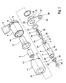
- FIG. 1 From Figures 1 to 3 is clearly an electromagnetic hydraulic valve 1, which serves as a 3/2-way switching valve for controlling a variable valve train an internal combustion engine is formed and substantially an electromagnet 2 with an axially movable armature 3 and from a valve member 4 having two valve seats 5, 6 and one corresponding to the valve seat 6 Closing ball 7 consists.
- an electromagnetic hydraulic valve 1 which serves as a 3/2-way switching valve for controlling a variable valve train an internal combustion engine is formed and substantially an electromagnet 2 with an axially movable armature 3 and from a valve member 4 having two valve seats 5, 6 and one corresponding to the valve seat 6 Closing ball 7 consists.
- the solenoid 2 is doing by a hollow cylindrical plastic bobbin 8 with an electrical Plug contact 9, a recorded in the bobbin 8 coil winding 10 and a coil winding 10 enclosing the magnet housing 11th formed, wherein the magnet housing 11 as a deep-drawn cylinder tube sleeve is formed, one end face of an annular bottom 12 forming is angled into the sleeve interior and the other end face several flanged lugs 13 to the connection with the bobbin 8 has.
- Hollow cylinder of the plastic bobbin 8 is also in the usual way Way as the armature 3 of the electromagnet 2 receiving armature space 14 is formed, in which an upper magnetic pole 15 and a lower magnetic pole 16 protrude and lined with an amagnetic metal sleeve 17 is.
- FIGS. 2 and 3 show that within the hollow cylinder 20 of the valve housing 18 in each case between the Pressure port P and the consumer port A and between the consumer port A and the tank connection T one of the valve seats 5, 6 of the Valve part 4 is arranged, wherein the valve seats 5, 6 each as axial breakthrough in the bottom 21, 22 of two cup-shaped deep-drawn parts 23, 24 are formed are, over their peripheral surfaces by press fit in the hollow cylinder 20th the valve housing 18 are attached. With the thus formed valve part.
- valve member 4 for sealing the valve seat against Pressure medium leaks additionally has an outer sealing ring 25.
- valve housing 18 of the valve member 4 and the lower magnetic pole 16 of the electromagnet 2 inventively designed as non-cutting producible items are.
- the lower magnetic pole 16 with the mounting flange 26 of the hydraulic valve 1 additionally formed as a one-piece integral component, which at the same time provided as a plug-in receptacle for the valve housing 18 of the valve member 4 is.
- valve housing 18 of the valve member 4 in this case as a simple cylindrical Pipe section is formed, which is separated by non-cutting a long pipe is cut to size and which by punching axially and offset by 90 ° to each other, simple radial openings in its lateral surface 19 with the consumer port A and the tank connection T of the hydraulic valve 1 is provided.
- the lower magnetic pole 16 In the bottom 30 of its sleeve part 28 points the lower magnetic pole 16 also has a circular cutout 31, in which the armature 3 when energizing the electromagnet 2 partially dips.
- the diameter of the Magnet armature 3 at the valve-side end side In order to achieve an optimal transition of the magnetic field lines from the armature 3 to reach the lower magnetic pole 16, the diameter of the Magnet armature 3 at the valve-side end side by means of an integrally formed Stage to the diameter of the punched 31 in the bottom 30 of the lower magnetic pole 16 adapted.
- This second designed as a plastic injection molded closure member 36 is particularly clearly shown in Figures 2 and 3, from which can be seen is that this essentially from a cylindrical pin 38 with three by 120 ° offset from each other on the lateral surface integrally formed radial Axial Adjustsrippen 39 exists.
- These axial guide ribs 39 are on the anchor side of the Front side of the armature 3 and serve to center the second Closing member 36 within the valve housing 18.
- the the centering pin 37 opposite valve-side end side of the second closing body 36th is moreover as standing in operative connection with the first valve seat 5 Closing cone 40 is formed, which extends axially through one with the loose closing ball 7 for the second valve seat 6 operatively connected plunger pin 41st continues.
- the loose closing ball 7 is axially movable within a Plastic cage 42 arranged at one in the mouth of the valve body 18 pressable perforated disc is formed and an exact system of Ensured closing ball 7 in the valve seat 6.
Landscapes
- Engineering & Computer Science (AREA)
- General Engineering & Computer Science (AREA)
- Mechanical Engineering (AREA)
- Magnetically Actuated Valves (AREA)
- Valve Device For Special Equipments (AREA)
Applications Claiming Priority (2)
| Application Number | Priority Date | Filing Date | Title |
|---|---|---|---|
| DE2003159363 DE10359363A1 (de) | 2003-12-18 | 2003-12-18 | Elektromagnetisches Hydraulikventil, inbesondere 3/2-Wegeschaltventil zur Steuerung eines variablen Ventiltriebes einer Brennkraftmaschine |
| DE10359363 | 2003-12-18 |
Publications (2)
| Publication Number | Publication Date |
|---|---|
| EP1544525A1 true EP1544525A1 (fr) | 2005-06-22 |
| EP1544525B1 EP1544525B1 (fr) | 2006-05-17 |
Family
ID=34485452
Family Applications (1)
| Application Number | Title | Priority Date | Filing Date |
|---|---|---|---|
| EP20040027358 Expired - Lifetime EP1544525B1 (fr) | 2003-12-18 | 2004-11-18 | Electrovanne hydraulique |
Country Status (4)
| Country | Link |
|---|---|
| US (1) | US7137411B2 (fr) |
| EP (1) | EP1544525B1 (fr) |
| AT (1) | ATE326658T1 (fr) |
| DE (2) | DE10359363A1 (fr) |
Cited By (7)
| Publication number | Priority date | Publication date | Assignee | Title |
|---|---|---|---|---|
| DE102005022710A1 (de) * | 2004-07-19 | 2006-03-16 | Continental Teves Ag & Co. Ohg | Elektrisch ansteuerbares Ventil |
| WO2007025600A1 (fr) * | 2005-07-27 | 2007-03-08 | Schaeffler Kg | Electrovanne hydraulique |
| WO2008028802A1 (fr) * | 2006-09-08 | 2008-03-13 | Schaeffler Kg | Unité d'actionnement électromagnétique |
| CN100422614C (zh) * | 2005-08-17 | 2008-10-01 | 浙江三花制冷集团有限公司 | 电磁阀用电磁线圈 |
| EP1793149A3 (fr) * | 2005-12-01 | 2009-12-02 | Schaeffler KG | Actionneur électromagnétique |
| WO2010086057A1 (fr) * | 2009-01-28 | 2010-08-05 | Schaeffler Technologies Gmbh & Co. Kg | Distributeur hydraulique |
| EP3150810A3 (fr) * | 2013-03-14 | 2017-07-05 | Eaton Corporation | Soupape de commande d'huile avec un solenoid |
Families Citing this family (35)
| Publication number | Priority date | Publication date | Assignee | Title |
|---|---|---|---|---|
| DE10153019A1 (de) * | 2001-10-26 | 2003-05-08 | Ina Schaeffler Kg | Elektromagnet, insbesondere Proportionalmagnet zur Betätigung eines hydraulischen Ventils |
| DE10359364B4 (de) * | 2003-12-18 | 2012-10-11 | Schaeffler Technologies Gmbh & Co. Kg | Elektromagnetisches Hydraulikventil, insbesondere 3/2-Wegeschaltventil zur Steuerung eines varialblen Ventiltriebes einer Brennkraftmaschine |
| DE102004057573B4 (de) * | 2004-11-30 | 2013-05-02 | Schaeffler Technologies AG & Co. KG | Elektromagnetisch ansteuerbares Wegeventil |
| DE102005008164A1 (de) * | 2005-02-23 | 2006-08-31 | Schaeffler Kg | Wegeventil mit elektromagnetischer Ansteuerung |
| FR2887005B1 (fr) * | 2005-06-14 | 2009-04-24 | Bontaz Ct Soc Par Actions Simp | Electrovanne a epaulement rapporte |
| DE102005034939A1 (de) * | 2005-07-27 | 2007-02-01 | Schaeffler Kg | Elektromagnetische Stelleinheit |
| DE102005041395B4 (de) * | 2005-09-01 | 2014-11-27 | Schaeffler Technologies Gmbh & Co. Kg | Hydraulisches Wegeventil |
| DE102006054185A1 (de) * | 2006-11-16 | 2008-05-21 | Robert Bosch Gmbh | Magnetventil |
| DE102007014559A1 (de) * | 2007-03-27 | 2008-10-02 | Robert Bosch Gmbh | Druckrohr für ein Wegemesssystem |
| DE102007036924A1 (de) | 2007-08-04 | 2009-02-05 | Schaeffler Kg | Elektromagnetische Stelleinheit |
| US20100019186A1 (en) * | 2008-07-25 | 2010-01-28 | Eaton Corporation | Engine valve assembly with valve can mountable to an engine cover |
| DE102008035908A1 (de) | 2008-08-02 | 2010-02-04 | Schaeffler Kg | Hydraulisches Wegeventil |
| DE102008060069A1 (de) | 2008-12-02 | 2010-06-10 | Schaeffler Kg | Hydraulisches Wegeventil |
| DE102009018044A1 (de) | 2009-04-18 | 2010-10-21 | Schaeffler Technologies Gmbh & Co. Kg | Hydraulisches Wegeventil |
| US8316888B2 (en) * | 2009-06-17 | 2012-11-27 | Eaton Corporation | Fluid-biased hydraulic control valve |
| US8443839B2 (en) * | 2009-10-20 | 2013-05-21 | Eaton Corporation | Fluid-biased hydraulic control valve with armature piston |
| DE102011006855A1 (de) * | 2011-04-06 | 2012-10-11 | Robert Bosch Gmbh | Schieberventil mit einem Gehäuse und einem in dem Gehäuse geführten Schieber |
| DE102012104470A1 (de) * | 2011-05-27 | 2012-11-29 | Svm Schultz Verwaltungs-Gmbh & Co. Kg | Druckregelventil mit Blende |
| EP2527944B1 (fr) * | 2011-05-27 | 2020-11-25 | SVM Schultz Verwaltungs-GmbH & Co. KG | Vanne de régulation de pression à commande électromagnétique |
| US8436704B1 (en) * | 2011-11-09 | 2013-05-07 | Caterpillar Inc. | Protected powder metal stator core and solenoid actuator using same |
| DE102011086316A1 (de) * | 2011-11-14 | 2013-05-16 | Robert Bosch Gmbh | Magnetventil |
| JP5925504B2 (ja) * | 2012-02-03 | 2016-05-25 | 日立オートモティブシステムズ株式会社 | 電磁弁 |
| FR2997456B1 (fr) * | 2012-10-30 | 2014-11-28 | Delphi Technologies Holding | Vanne haute pression |
| WO2014078345A1 (fr) | 2012-11-14 | 2014-05-22 | Schaeffler Technologies AG & Co. KG | Plaque d'électrovanne |
| DE102013220877A1 (de) * | 2013-10-15 | 2015-04-16 | Continental Automotive Gmbh | Ventil |
| US9377124B2 (en) * | 2013-10-15 | 2016-06-28 | Continental Automotive Systems, Inc. | Normally low solenoid valve assembly |
| US9945492B2 (en) * | 2013-10-15 | 2018-04-17 | Continental Automotive Systems, Inc. | Normally high solenoid assembly |
| JP2017141885A (ja) * | 2016-02-10 | 2017-08-17 | 日本電産トーソク株式会社 | 電磁弁のソレノイド |
| EP3244425A1 (fr) * | 2016-02-23 | 2017-11-15 | Rausch und Pausch GmbH | Tube polaire pour électroaimants et électrovannes et procédé et dispositif destinés à sa fabrication |
| US10054245B2 (en) | 2016-12-15 | 2018-08-21 | Delphi Technologies Ip Limited | Valve assembly with vent port between supply port and control port |
| DE102018110755A1 (de) * | 2017-08-21 | 2019-02-21 | ECO Holding 1 GmbH | Elektrohydraulisches Ventil und Verfahren zur Herstellung eines elektrohydraulischen Ventils |
| DE102018219428A1 (de) * | 2018-11-14 | 2020-05-14 | Robert Bosch Gmbh | Elektromagnetisch betätigbares hydraulisches Einbauventil |
| CN211501810U (zh) | 2019-10-21 | 2020-09-15 | 浙江盾安禾田金属有限公司 | 先导阀 |
| CN113048280A (zh) * | 2021-03-09 | 2021-06-29 | 无锡恒捷磁感技术有限公司 | 一种具有密封高稳定性的进油阀 |
| CN217381870U (zh) * | 2021-03-23 | 2022-09-06 | 盾安汽车热管理科技有限公司 | 一种电磁阀及电磁阀组件 |
Citations (7)
| Publication number | Priority date | Publication date | Assignee | Title |
|---|---|---|---|---|
| DE2124484A1 (de) * | 1971-05-18 | 1972-11-30 | Zahnradfabrik Friedrichshafen | Elektromagnetisch betätigtes Ventil |
| US4951703A (en) * | 1987-08-27 | 1990-08-28 | Robert Bosch Gmbh | Electromagnetic wave |
| DE4007009A1 (de) * | 1989-03-06 | 1990-09-13 | Telemecanique Electrique | Magnetventil und verfahren zu seiner montage |
| DE4003606A1 (de) * | 1990-02-07 | 1990-12-20 | Bosch Gmbh Robert | Elektromagnetisch betaetigtes ventil, insbesondere hydraulisches hochdruckventil fuer fahrzeug-bremsanlag en |
| US5102096A (en) * | 1990-04-30 | 1992-04-07 | Robert Bosch Gmbh | Connection of a magnet valve to a housing block |
| DE19908440A1 (de) * | 1999-02-22 | 2000-08-24 | Mannesmann Rexroth Ag | Wegesitzventil |
| US6273122B1 (en) * | 1998-09-16 | 2001-08-14 | Robert Bosch Gmbh | Magnetic valve, especially for use in a module for an electrohydraulic gear unit controller |
Family Cites Families (9)
| Publication number | Priority date | Publication date | Assignee | Title |
|---|---|---|---|---|
| US4998559A (en) * | 1988-09-13 | 1991-03-12 | Coltec Industries Inc. | Solenoid operated pressure control valve |
| US5577534A (en) * | 1995-06-02 | 1996-11-26 | Applied Power Inc. | Load sensing proportional pressure control valve |
| US5651391A (en) * | 1996-05-06 | 1997-07-29 | Borg-Warner Automotive, Inc. | Three-way solenoid valve |
| DE19729935B4 (de) * | 1997-07-12 | 2006-11-16 | Hydraulik-Ring Gmbh | Hydraulisches Einbauventil, insbesondere für eine hydraulische Nockenwellenverstellung an einem Kraftfahrzeugmotor |
| JPH11287349A (ja) * | 1998-02-06 | 1999-10-19 | Denso Corp | 電磁制御弁 |
| DE19810330A1 (de) * | 1998-03-11 | 1999-09-16 | Mannesmann Rexroth Ag | Magnetventil |
| DE50012876D1 (de) * | 1999-02-22 | 2006-07-20 | Hydraulik Ring Gmbh | Wegesitzventil |
| DE10003205A1 (de) * | 1999-05-14 | 2000-11-30 | Continental Teves Ag & Co Ohg | Elektromagnet |
| DE19934846A1 (de) * | 1999-07-24 | 2001-01-25 | Hydraulik Ring Gmbh | Elektromagnet und hydraulisches Ventil mit einem Elektromagneten |
-
2003
- 2003-12-18 DE DE2003159363 patent/DE10359363A1/de not_active Withdrawn
-
2004
- 2004-11-18 AT AT04027358T patent/ATE326658T1/de not_active IP Right Cessation
- 2004-11-18 EP EP20040027358 patent/EP1544525B1/fr not_active Expired - Lifetime
- 2004-11-18 DE DE200450000582 patent/DE502004000582D1/de not_active Expired - Lifetime
- 2004-12-17 US US11/016,186 patent/US7137411B2/en not_active Expired - Fee Related
Patent Citations (7)
| Publication number | Priority date | Publication date | Assignee | Title |
|---|---|---|---|---|
| DE2124484A1 (de) * | 1971-05-18 | 1972-11-30 | Zahnradfabrik Friedrichshafen | Elektromagnetisch betätigtes Ventil |
| US4951703A (en) * | 1987-08-27 | 1990-08-28 | Robert Bosch Gmbh | Electromagnetic wave |
| DE4007009A1 (de) * | 1989-03-06 | 1990-09-13 | Telemecanique Electrique | Magnetventil und verfahren zu seiner montage |
| DE4003606A1 (de) * | 1990-02-07 | 1990-12-20 | Bosch Gmbh Robert | Elektromagnetisch betaetigtes ventil, insbesondere hydraulisches hochdruckventil fuer fahrzeug-bremsanlag en |
| US5102096A (en) * | 1990-04-30 | 1992-04-07 | Robert Bosch Gmbh | Connection of a magnet valve to a housing block |
| US6273122B1 (en) * | 1998-09-16 | 2001-08-14 | Robert Bosch Gmbh | Magnetic valve, especially for use in a module for an electrohydraulic gear unit controller |
| DE19908440A1 (de) * | 1999-02-22 | 2000-08-24 | Mannesmann Rexroth Ag | Wegesitzventil |
Cited By (10)
| Publication number | Priority date | Publication date | Assignee | Title |
|---|---|---|---|---|
| DE102005022710A1 (de) * | 2004-07-19 | 2006-03-16 | Continental Teves Ag & Co. Ohg | Elektrisch ansteuerbares Ventil |
| US7669831B2 (en) | 2004-07-19 | 2010-03-02 | Continental Teves Ag & Co. Ohg | Electrically controllable valve |
| WO2007025600A1 (fr) * | 2005-07-27 | 2007-03-08 | Schaeffler Kg | Electrovanne hydraulique |
| CN101233355B (zh) * | 2005-07-27 | 2011-03-23 | 谢夫勒科技有限两合公司 | 电磁液压阀 |
| US7971607B2 (en) | 2005-07-27 | 2011-07-05 | Schaeffler Technologies Gmbh & Co. Kg | Electromagnetic hydraulic valve |
| CN100422614C (zh) * | 2005-08-17 | 2008-10-01 | 浙江三花制冷集团有限公司 | 电磁阀用电磁线圈 |
| EP1793149A3 (fr) * | 2005-12-01 | 2009-12-02 | Schaeffler KG | Actionneur électromagnétique |
| WO2008028802A1 (fr) * | 2006-09-08 | 2008-03-13 | Schaeffler Kg | Unité d'actionnement électromagnétique |
| WO2010086057A1 (fr) * | 2009-01-28 | 2010-08-05 | Schaeffler Technologies Gmbh & Co. Kg | Distributeur hydraulique |
| EP3150810A3 (fr) * | 2013-03-14 | 2017-07-05 | Eaton Corporation | Soupape de commande d'huile avec un solenoid |
Also Published As
| Publication number | Publication date |
|---|---|
| US7137411B2 (en) | 2006-11-21 |
| US20050189510A1 (en) | 2005-09-01 |
| DE10359363A1 (de) | 2005-07-14 |
| DE502004000582D1 (de) | 2006-06-22 |
| ATE326658T1 (de) | 2006-06-15 |
| EP1544525B1 (fr) | 2006-05-17 |
Similar Documents
| Publication | Publication Date | Title |
|---|---|---|
| EP1544525B1 (fr) | Electrovanne hydraulique | |
| DE10359364B4 (de) | Elektromagnetisches Hydraulikventil, insbesondere 3/2-Wegeschaltventil zur Steuerung eines varialblen Ventiltriebes einer Brennkraftmaschine | |
| EP1561058B1 (fr) | Electrovanne hydraulique, notamment distributeur 3/2, pour la commande d'une distribution variable d'un moteur a combustion interne | |
| EP1073070B1 (fr) | Electro-aimant et soupape hydraulique comprenant un électro-aimant | |
| DE4310719C2 (de) | Verfahren zur Herstellung eines Magnetkreises für ein Ventil | |
| EP1031731B1 (fr) | Soupape à voies multiples à siège | |
| EP0944769A1 (fr) | Soupape d'injection de carburant | |
| EP0951412A1 (fr) | Vanne magnetique | |
| EP0720691A1 (fr) | Pointeau pour soupape a actionnement electromagnetique et son procede de production | |
| EP0733162A1 (fr) | Procede de production d'un circuit magnetique pour soupape | |
| EP1855296A2 (fr) | Electroaimant | |
| EP3446013B1 (fr) | Dispositif soupape à commande électromagnétique | |
| DE102007005916A1 (de) | Doppelankermagnetventil mit zwei Ventilöffnungen und mindestens einem die Ventilöffnungen verbindenden Kanal | |
| DE4439695C2 (de) | Magnetventil und dessen Verwendung | |
| DE102023110852A1 (de) | Magnetventilbaugruppe und verfahren zum betreiben dieser | |
| DE4039324C2 (de) | Elektromagnetventil | |
| DE102015217516A1 (de) | Ventil zum Zumessen eines Fluids | |
| DE19932747B4 (de) | Verfahren zur Herstellung eines Druckregelventils für ein Automatikgetriebe eines Kraftfahrzeuges und nach dem Verfahren hergestelltes Druckregelventil | |
| EP1924795A1 (fr) | Soupape de distribution hydraulique | |
| DE19908440A1 (de) | Wegesitzventil | |
| DE102022205870A1 (de) | Elektromagnetventil für eine Kraftfahrzeugbremsanlage mit einem Mittel zur Restluftspalteinstellung und ein Verfahren zur Montage eines Elektromagnetventils | |
| DE202016102130U1 (de) | Elektromagnetisch betätigbare Ventilvorrichtung | |
| DE102021133235A1 (de) | Elektromagnetische Vorrichtung, sowie Verfahren zum Herstellen einer solchen elektromagnetischen Vorrichtung | |
| DE102018215493A1 (de) | Herstellungsverfahren für ein Ankerführungsrohr, einen elektromagnetischen Aktor und ein Magnetventil | |
| DE19546384A1 (de) | Elektrisch ansteuerbares Magnetventil |
Legal Events
| Date | Code | Title | Description |
|---|---|---|---|
| PUAI | Public reference made under article 153(3) epc to a published international application that has entered the european phase |
Free format text: ORIGINAL CODE: 0009012 |
|
| 17P | Request for examination filed |
Effective date: 20041118 |
|
| AK | Designated contracting states |
Kind code of ref document: A1 Designated state(s): AT BE BG CH CY CZ DE DK EE ES FI FR GB GR HU IE IS IT LI LU MC NL PL PT RO SE SI SK TR |
|
| AX | Request for extension of the european patent |
Extension state: AL HR LT LV MK YU |
|
| GRAP | Despatch of communication of intention to grant a patent |
Free format text: ORIGINAL CODE: EPIDOSNIGR1 |
|
| GRAS | Grant fee paid |
Free format text: ORIGINAL CODE: EPIDOSNIGR3 |
|
| AKX | Designation fees paid |
Designated state(s): AT BE BG CH CY CZ DE DK EE ES FI FR GB GR HU IE IS IT LI LU MC NL PL PT RO SE SI SK TR |
|
| GRAA | (expected) grant |
Free format text: ORIGINAL CODE: 0009210 |
|
| RAP1 | Party data changed (applicant data changed or rights of an application transferred) |
Owner name: SCHAEFFLER KG |
|
| AK | Designated contracting states |
Kind code of ref document: B1 Designated state(s): AT BE BG CH CY CZ DE DK EE ES FI FR GB GR HU IE IS IT LI LU MC NL PL PT RO SE SI SK TR |
|
| PG25 | Lapsed in a contracting state [announced via postgrant information from national office to epo] |
Ref country code: IT Free format text: LAPSE BECAUSE OF FAILURE TO SUBMIT A TRANSLATION OF THE DESCRIPTION OR TO PAY THE FEE WITHIN THE PRESCRIBED TIME-LIMIT;WARNING: LAPSES OF ITALIAN PATENTS WITH EFFECTIVE DATE BEFORE 2007 MAY HAVE OCCURRED AT ANY TIME BEFORE 2007. THE CORRECT EFFECTIVE DATE MAY BE DIFFERENT FROM THE ONE RECORDED. Effective date: 20060517 Ref country code: SI Free format text: LAPSE BECAUSE OF FAILURE TO SUBMIT A TRANSLATION OF THE DESCRIPTION OR TO PAY THE FEE WITHIN THE PRESCRIBED TIME-LIMIT Effective date: 20060517 Ref country code: RO Free format text: LAPSE BECAUSE OF FAILURE TO SUBMIT A TRANSLATION OF THE DESCRIPTION OR TO PAY THE FEE WITHIN THE PRESCRIBED TIME-LIMIT Effective date: 20060517 Ref country code: FI Free format text: LAPSE BECAUSE OF FAILURE TO SUBMIT A TRANSLATION OF THE DESCRIPTION OR TO PAY THE FEE WITHIN THE PRESCRIBED TIME-LIMIT Effective date: 20060517 Ref country code: SK Free format text: LAPSE BECAUSE OF FAILURE TO SUBMIT A TRANSLATION OF THE DESCRIPTION OR TO PAY THE FEE WITHIN THE PRESCRIBED TIME-LIMIT Effective date: 20060517 Ref country code: IE Free format text: LAPSE BECAUSE OF FAILURE TO SUBMIT A TRANSLATION OF THE DESCRIPTION OR TO PAY THE FEE WITHIN THE PRESCRIBED TIME-LIMIT Effective date: 20060517 Ref country code: NL Free format text: LAPSE BECAUSE OF FAILURE TO SUBMIT A TRANSLATION OF THE DESCRIPTION OR TO PAY THE FEE WITHIN THE PRESCRIBED TIME-LIMIT Effective date: 20060517 Ref country code: CZ Free format text: LAPSE BECAUSE OF FAILURE TO SUBMIT A TRANSLATION OF THE DESCRIPTION OR TO PAY THE FEE WITHIN THE PRESCRIBED TIME-LIMIT Effective date: 20060517 Ref country code: PL Free format text: LAPSE BECAUSE OF FAILURE TO SUBMIT A TRANSLATION OF THE DESCRIPTION OR TO PAY THE FEE WITHIN THE PRESCRIBED TIME-LIMIT Effective date: 20060517 |
|
| REG | Reference to a national code |
Ref country code: GB Ref legal event code: FG4D Free format text: NOT ENGLISH |
|
| REG | Reference to a national code |
Ref country code: CH Ref legal event code: EP |
|
| REG | Reference to a national code |
Ref country code: IE Ref legal event code: FG4D Free format text: LANGUAGE OF EP DOCUMENT: GERMAN |
|
| REF | Corresponds to: |
Ref document number: 502004000582 Country of ref document: DE Date of ref document: 20060622 Kind code of ref document: P |
|
| GBT | Gb: translation of ep patent filed (gb section 77(6)(a)/1977) |
Effective date: 20060712 |
|
| PG25 | Lapsed in a contracting state [announced via postgrant information from national office to epo] |
Ref country code: DK Free format text: LAPSE BECAUSE OF FAILURE TO SUBMIT A TRANSLATION OF THE DESCRIPTION OR TO PAY THE FEE WITHIN THE PRESCRIBED TIME-LIMIT Effective date: 20060817 |
|
| PG25 | Lapsed in a contracting state [announced via postgrant information from national office to epo] |
Ref country code: ES Free format text: LAPSE BECAUSE OF FAILURE TO SUBMIT A TRANSLATION OF THE DESCRIPTION OR TO PAY THE FEE WITHIN THE PRESCRIBED TIME-LIMIT Effective date: 20060828 |
|
| REG | Reference to a national code |
Ref country code: SE Ref legal event code: TRGR |
|
| PG25 | Lapsed in a contracting state [announced via postgrant information from national office to epo] |
Ref country code: PT Free format text: LAPSE BECAUSE OF FAILURE TO SUBMIT A TRANSLATION OF THE DESCRIPTION OR TO PAY THE FEE WITHIN THE PRESCRIBED TIME-LIMIT Effective date: 20061017 |
|
| NLV1 | Nl: lapsed or annulled due to failure to fulfill the requirements of art. 29p and 29m of the patents act | ||
| ET | Fr: translation filed | ||
| PG25 | Lapsed in a contracting state [announced via postgrant information from national office to epo] |
Ref country code: MC Free format text: LAPSE BECAUSE OF NON-PAYMENT OF DUE FEES Effective date: 20061130 Ref country code: BE Free format text: LAPSE BECAUSE OF NON-PAYMENT OF DUE FEES Effective date: 20061130 |
|
| REG | Reference to a national code |
Ref country code: IE Ref legal event code: FD4D |
|
| PLBE | No opposition filed within time limit |
Free format text: ORIGINAL CODE: 0009261 |
|
| STAA | Information on the status of an ep patent application or granted ep patent |
Free format text: STATUS: NO OPPOSITION FILED WITHIN TIME LIMIT |
|
| 26N | No opposition filed |
Effective date: 20070220 |
|
| BERE | Be: lapsed |
Owner name: SCHAEFFLER K.G. Effective date: 20061130 |
|
| PG25 | Lapsed in a contracting state [announced via postgrant information from national office to epo] |
Ref country code: AT Free format text: LAPSE BECAUSE OF NON-PAYMENT OF DUE FEES Effective date: 20061118 |
|
| PG25 | Lapsed in a contracting state [announced via postgrant information from national office to epo] |
Ref country code: GR Free format text: LAPSE BECAUSE OF FAILURE TO SUBMIT A TRANSLATION OF THE DESCRIPTION OR TO PAY THE FEE WITHIN THE PRESCRIBED TIME-LIMIT Effective date: 20060818 |
|
| PG25 | Lapsed in a contracting state [announced via postgrant information from national office to epo] |
Ref country code: EE Free format text: LAPSE BECAUSE OF FAILURE TO SUBMIT A TRANSLATION OF THE DESCRIPTION OR TO PAY THE FEE WITHIN THE PRESCRIBED TIME-LIMIT Effective date: 20060517 Ref country code: BG Free format text: LAPSE BECAUSE OF FAILURE TO SUBMIT A TRANSLATION OF THE DESCRIPTION OR TO PAY THE FEE WITHIN THE PRESCRIBED TIME-LIMIT Effective date: 20060817 |
|
| PG25 | Lapsed in a contracting state [announced via postgrant information from national office to epo] |
Ref country code: TR Free format text: LAPSE BECAUSE OF FAILURE TO SUBMIT A TRANSLATION OF THE DESCRIPTION OR TO PAY THE FEE WITHIN THE PRESCRIBED TIME-LIMIT Effective date: 20060517 Ref country code: LU Free format text: LAPSE BECAUSE OF NON-PAYMENT OF DUE FEES Effective date: 20061118 Ref country code: IS Free format text: LAPSE BECAUSE OF FAILURE TO SUBMIT A TRANSLATION OF THE DESCRIPTION OR TO PAY THE FEE WITHIN THE PRESCRIBED TIME-LIMIT Effective date: 20060517 Ref country code: HU Free format text: LAPSE BECAUSE OF FAILURE TO SUBMIT A TRANSLATION OF THE DESCRIPTION OR TO PAY THE FEE WITHIN THE PRESCRIBED TIME-LIMIT Effective date: 20061118 |
|
| PG25 | Lapsed in a contracting state [announced via postgrant information from national office to epo] |
Ref country code: CY Free format text: LAPSE BECAUSE OF FAILURE TO SUBMIT A TRANSLATION OF THE DESCRIPTION OR TO PAY THE FEE WITHIN THE PRESCRIBED TIME-LIMIT Effective date: 20060517 |
|
| REG | Reference to a national code |
Ref country code: CH Ref legal event code: PL |
|
| PG25 | Lapsed in a contracting state [announced via postgrant information from national office to epo] |
Ref country code: LI Free format text: LAPSE BECAUSE OF NON-PAYMENT OF DUE FEES Effective date: 20081130 Ref country code: CH Free format text: LAPSE BECAUSE OF NON-PAYMENT OF DUE FEES Effective date: 20081130 |
|
| PGFP | Annual fee paid to national office [announced via postgrant information from national office to epo] |
Ref country code: IT Payment date: 20101127 Year of fee payment: 7 Ref country code: GB Payment date: 20101130 Year of fee payment: 7 |
|
| REG | Reference to a national code |
Ref country code: GB Ref legal event code: 732E Free format text: REGISTERED BETWEEN 20110407 AND 20110413 |
|
| PGFP | Annual fee paid to national office [announced via postgrant information from national office to epo] |
Ref country code: FR Payment date: 20111214 Year of fee payment: 8 Ref country code: SE Payment date: 20111130 Year of fee payment: 8 |
|
| REG | Reference to a national code |
Ref country code: DE Ref legal event code: R081 Ref document number: 502004000582 Country of ref document: DE Owner name: SCHAEFFLER TECHNOLOGIES AG & CO. KG, DE Free format text: FORMER OWNER: SCHAEFFLER TECHNOLOGIES GMBH & CO. KG, 91074 HERZOGENAURACH, DE Effective date: 20120828 Ref country code: DE Ref legal event code: R081 Ref document number: 502004000582 Country of ref document: DE Owner name: SCHAEFFLER TECHNOLOGIES GMBH & CO. KG, DE Free format text: FORMER OWNER: SCHAEFFLER TECHNOLOGIES GMBH & CO. KG, 91074 HERZOGENAURACH, DE Effective date: 20120828 |
|
| GBPC | Gb: european patent ceased through non-payment of renewal fee |
Effective date: 20121118 |
|
| PG25 | Lapsed in a contracting state [announced via postgrant information from national office to epo] |
Ref country code: SE Free format text: LAPSE BECAUSE OF NON-PAYMENT OF DUE FEES Effective date: 20121119 |
|
| REG | Reference to a national code |
Ref country code: FR Ref legal event code: ST Effective date: 20130731 |
|
| PG25 | Lapsed in a contracting state [announced via postgrant information from national office to epo] |
Ref country code: IT Free format text: LAPSE BECAUSE OF NON-PAYMENT OF DUE FEES Effective date: 20121118 |
|
| PG25 | Lapsed in a contracting state [announced via postgrant information from national office to epo] |
Ref country code: GB Free format text: LAPSE BECAUSE OF NON-PAYMENT OF DUE FEES Effective date: 20121118 Ref country code: FR Free format text: LAPSE BECAUSE OF NON-PAYMENT OF DUE FEES Effective date: 20121130 |
|
| REG | Reference to a national code |
Ref country code: DE Ref legal event code: R081 Ref document number: 502004000582 Country of ref document: DE Owner name: SCHAEFFLER TECHNOLOGIES GMBH & CO. KG, DE Free format text: FORMER OWNER: SCHAEFFLER TECHNOLOGIES AG & CO. KG, 91074 HERZOGENAURACH, DE Effective date: 20140212 Ref country code: DE Ref legal event code: R081 Ref document number: 502004000582 Country of ref document: DE Owner name: SCHAEFFLER TECHNOLOGIES AG & CO. KG, DE Free format text: FORMER OWNER: SCHAEFFLER TECHNOLOGIES AG & CO. KG, 91074 HERZOGENAURACH, DE Effective date: 20140212 |
|
| REG | Reference to a national code |
Ref country code: DE Ref legal event code: R081 Ref document number: 502004000582 Country of ref document: DE Owner name: SCHAEFFLER TECHNOLOGIES AG & CO. KG, DE Free format text: FORMER OWNER: SCHAEFFLER TECHNOLOGIES GMBH & CO. KG, 91074 HERZOGENAURACH, DE Effective date: 20150123 |
|
| PGFP | Annual fee paid to national office [announced via postgrant information from national office to epo] |
Ref country code: DE Payment date: 20180131 Year of fee payment: 14 |
|
| REG | Reference to a national code |
Ref country code: DE Ref legal event code: R119 Ref document number: 502004000582 Country of ref document: DE |
|
| PG25 | Lapsed in a contracting state [announced via postgrant information from national office to epo] |
Ref country code: DE Free format text: LAPSE BECAUSE OF NON-PAYMENT OF DUE FEES Effective date: 20190601 |
|
| P01 | Opt-out of the competence of the unified patent court (upc) registered |
Effective date: 20230522 |