EP1544559A1 - Verfahren und Vorrichtung zur Tieftemperaturzerlegung von Luft - Google Patents
Verfahren und Vorrichtung zur Tieftemperaturzerlegung von Luft Download PDFInfo
- Publication number
- EP1544559A1 EP1544559A1 EP04005171A EP04005171A EP1544559A1 EP 1544559 A1 EP1544559 A1 EP 1544559A1 EP 04005171 A EP04005171 A EP 04005171A EP 04005171 A EP04005171 A EP 04005171A EP 1544559 A1 EP1544559 A1 EP 1544559A1
- Authority
- EP
- European Patent Office
- Prior art keywords
- liquid
- cryogenic air
- air separation
- separation plant
- stream
- Prior art date
- Legal status (The legal status is an assumption and is not a legal conclusion. Google has not performed a legal analysis and makes no representation as to the accuracy of the status listed.)
- Withdrawn
Links
- 238000000926 separation method Methods 0.000 title claims abstract description 108
- 238000000034 method Methods 0.000 title claims description 23
- 239000000047 product Substances 0.000 claims description 37
- 239000007788 liquid Substances 0.000 claims description 36
- 239000012263 liquid product Substances 0.000 claims description 35
- 239000013529 heat transfer fluid Substances 0.000 claims description 26
- 238000007906 compression Methods 0.000 claims description 11
- 238000001704 evaporation Methods 0.000 claims description 11
- 230000006835 compression Effects 0.000 claims description 9
- 230000008020 evaporation Effects 0.000 claims description 9
- 238000001816 cooling Methods 0.000 claims description 4
- 239000012530 fluid Substances 0.000 claims description 4
- 230000000274 adsorptive effect Effects 0.000 claims description 2
- 238000000354 decomposition reaction Methods 0.000 claims description 2
- 239000013067 intermediate product Substances 0.000 claims 3
- 238000010438 heat treatment Methods 0.000 claims 2
- 238000004140 cleaning Methods 0.000 claims 1
- 238000009834 vaporization Methods 0.000 claims 1
- 230000008016 vaporization Effects 0.000 claims 1
- QVGXLLKOCUKJST-UHFFFAOYSA-N atomic oxygen Chemical compound [O] QVGXLLKOCUKJST-UHFFFAOYSA-N 0.000 abstract description 11
- 239000001301 oxygen Substances 0.000 abstract description 11
- 229910052760 oxygen Inorganic materials 0.000 abstract description 11
- MYMOFIZGZYHOMD-UHFFFAOYSA-N Dioxygen Chemical compound O=O MYMOFIZGZYHOMD-UHFFFAOYSA-N 0.000 abstract description 10
- 230000000712 assembly Effects 0.000 abstract 1
- 238000000429 assembly Methods 0.000 abstract 1
- IJGRMHOSHXDMSA-UHFFFAOYSA-N Atomic nitrogen Chemical compound N#N IJGRMHOSHXDMSA-UHFFFAOYSA-N 0.000 description 6
- 238000005056 compaction Methods 0.000 description 3
- 230000002349 favourable effect Effects 0.000 description 3
- 229910052757 nitrogen Inorganic materials 0.000 description 3
- XLYOFNOQVPJJNP-UHFFFAOYSA-N water Substances O XLYOFNOQVPJJNP-UHFFFAOYSA-N 0.000 description 3
- XKRFYHLGVUSROY-UHFFFAOYSA-N Argon Chemical compound [Ar] XKRFYHLGVUSROY-UHFFFAOYSA-N 0.000 description 2
- 238000012423 maintenance Methods 0.000 description 2
- 241000883306 Huso huso Species 0.000 description 1
- 229910000831 Steel Inorganic materials 0.000 description 1
- 229910052786 argon Inorganic materials 0.000 description 1
- 239000003990 capacitor Substances 0.000 description 1
- 238000003889 chemical engineering Methods 0.000 description 1
- 239000000498 cooling water Substances 0.000 description 1
- 230000003292 diminished effect Effects 0.000 description 1
- 230000002706 hydrostatic effect Effects 0.000 description 1
- 230000010354 integration Effects 0.000 description 1
- 238000004519 manufacturing process Methods 0.000 description 1
- DOTMOQHOJINYBL-UHFFFAOYSA-N molecular nitrogen;molecular oxygen Chemical compound N#N.O=O DOTMOQHOJINYBL-UHFFFAOYSA-N 0.000 description 1
- 239000002808 molecular sieve Substances 0.000 description 1
- 229910052756 noble gas Inorganic materials 0.000 description 1
- 150000002835 noble gases Chemical class 0.000 description 1
- 238000005086 pumping Methods 0.000 description 1
- 238000000746 purification Methods 0.000 description 1
- 238000011084 recovery Methods 0.000 description 1
- URGAHOPLAPQHLN-UHFFFAOYSA-N sodium aluminosilicate Chemical compound [Na+].[Al+3].[O-][Si]([O-])=O.[O-][Si]([O-])=O URGAHOPLAPQHLN-UHFFFAOYSA-N 0.000 description 1
- 239000010959 steel Substances 0.000 description 1
Images
Classifications
-
- F—MECHANICAL ENGINEERING; LIGHTING; HEATING; WEAPONS; BLASTING
- F25—REFRIGERATION OR COOLING; COMBINED HEATING AND REFRIGERATION SYSTEMS; HEAT PUMP SYSTEMS; MANUFACTURE OR STORAGE OF ICE; LIQUEFACTION SOLIDIFICATION OF GASES
- F25J—LIQUEFACTION, SOLIDIFICATION OR SEPARATION OF GASES OR GASEOUS OR LIQUEFIED GASEOUS MIXTURES BY PRESSURE AND COLD TREATMENT OR BY BRINGING THEM INTO THE SUPERCRITICAL STATE
- F25J3/00—Processes or apparatus for separating the constituents of gaseous or liquefied gaseous mixtures involving the use of liquefaction or solidification
- F25J3/02—Processes or apparatus for separating the constituents of gaseous or liquefied gaseous mixtures involving the use of liquefaction or solidification by rectification, i.e. by continuous interchange of heat and material between a vapour stream and a liquid stream
- F25J3/04—Processes or apparatus for separating the constituents of gaseous or liquefied gaseous mixtures involving the use of liquefaction or solidification by rectification, i.e. by continuous interchange of heat and material between a vapour stream and a liquid stream for air
- F25J3/04763—Start-up or control of the process; Details of the apparatus used
- F25J3/04769—Operation, control and regulation of the process; Instrumentation within the process
- F25J3/04812—Different modes, i.e. "runs" of operation
- F25J3/04824—Stopping of the process, e.g. defrosting or deriming; Back-up procedures
-
- F—MECHANICAL ENGINEERING; LIGHTING; HEATING; WEAPONS; BLASTING
- F25—REFRIGERATION OR COOLING; COMBINED HEATING AND REFRIGERATION SYSTEMS; HEAT PUMP SYSTEMS; MANUFACTURE OR STORAGE OF ICE; LIQUEFACTION SOLIDIFICATION OF GASES
- F25J—LIQUEFACTION, SOLIDIFICATION OR SEPARATION OF GASES OR GASEOUS OR LIQUEFIED GASEOUS MIXTURES BY PRESSURE AND COLD TREATMENT OR BY BRINGING THEM INTO THE SUPERCRITICAL STATE
- F25J3/00—Processes or apparatus for separating the constituents of gaseous or liquefied gaseous mixtures involving the use of liquefaction or solidification
- F25J3/02—Processes or apparatus for separating the constituents of gaseous or liquefied gaseous mixtures involving the use of liquefaction or solidification by rectification, i.e. by continuous interchange of heat and material between a vapour stream and a liquid stream
- F25J3/04—Processes or apparatus for separating the constituents of gaseous or liquefied gaseous mixtures involving the use of liquefaction or solidification by rectification, i.e. by continuous interchange of heat and material between a vapour stream and a liquid stream for air
- F25J3/04763—Start-up or control of the process; Details of the apparatus used
- F25J3/04866—Construction and layout of air fractionation equipments, e.g. valves, machines
- F25J3/04951—Arrangements of multiple air fractionation units or multiple equipments fulfilling the same process step, e.g. multiple trains in a network
-
- F—MECHANICAL ENGINEERING; LIGHTING; HEATING; WEAPONS; BLASTING
- F25—REFRIGERATION OR COOLING; COMBINED HEATING AND REFRIGERATION SYSTEMS; HEAT PUMP SYSTEMS; MANUFACTURE OR STORAGE OF ICE; LIQUEFACTION SOLIDIFICATION OF GASES
- F25J—LIQUEFACTION, SOLIDIFICATION OR SEPARATION OF GASES OR GASEOUS OR LIQUEFIED GASEOUS MIXTURES BY PRESSURE AND COLD TREATMENT OR BY BRINGING THEM INTO THE SUPERCRITICAL STATE
- F25J3/00—Processes or apparatus for separating the constituents of gaseous or liquefied gaseous mixtures involving the use of liquefaction or solidification
- F25J3/02—Processes or apparatus for separating the constituents of gaseous or liquefied gaseous mixtures involving the use of liquefaction or solidification by rectification, i.e. by continuous interchange of heat and material between a vapour stream and a liquid stream
- F25J3/04—Processes or apparatus for separating the constituents of gaseous or liquefied gaseous mixtures involving the use of liquefaction or solidification by rectification, i.e. by continuous interchange of heat and material between a vapour stream and a liquid stream for air
- F25J3/04763—Start-up or control of the process; Details of the apparatus used
- F25J3/04866—Construction and layout of air fractionation equipments, e.g. valves, machines
- F25J3/04951—Arrangements of multiple air fractionation units or multiple equipments fulfilling the same process step, e.g. multiple trains in a network
- F25J3/04957—Arrangements of multiple air fractionation units or multiple equipments fulfilling the same process step, e.g. multiple trains in a network and inter-connecting equipments upstream of the fractionation unit (s), i.e. at the "front-end"
-
- F—MECHANICAL ENGINEERING; LIGHTING; HEATING; WEAPONS; BLASTING
- F25—REFRIGERATION OR COOLING; COMBINED HEATING AND REFRIGERATION SYSTEMS; HEAT PUMP SYSTEMS; MANUFACTURE OR STORAGE OF ICE; LIQUEFACTION SOLIDIFICATION OF GASES
- F25J—LIQUEFACTION, SOLIDIFICATION OR SEPARATION OF GASES OR GASEOUS OR LIQUEFIED GASEOUS MIXTURES BY PRESSURE AND COLD TREATMENT OR BY BRINGING THEM INTO THE SUPERCRITICAL STATE
- F25J3/00—Processes or apparatus for separating the constituents of gaseous or liquefied gaseous mixtures involving the use of liquefaction or solidification
- F25J3/02—Processes or apparatus for separating the constituents of gaseous or liquefied gaseous mixtures involving the use of liquefaction or solidification by rectification, i.e. by continuous interchange of heat and material between a vapour stream and a liquid stream
- F25J3/04—Processes or apparatus for separating the constituents of gaseous or liquefied gaseous mixtures involving the use of liquefaction or solidification by rectification, i.e. by continuous interchange of heat and material between a vapour stream and a liquid stream for air
- F25J3/04763—Start-up or control of the process; Details of the apparatus used
- F25J3/04866—Construction and layout of air fractionation equipments, e.g. valves, machines
- F25J3/04951—Arrangements of multiple air fractionation units or multiple equipments fulfilling the same process step, e.g. multiple trains in a network
- F25J3/04963—Arrangements of multiple air fractionation units or multiple equipments fulfilling the same process step, e.g. multiple trains in a network and inter-connecting equipment within or downstream of the fractionation unit(s)
-
- F—MECHANICAL ENGINEERING; LIGHTING; HEATING; WEAPONS; BLASTING
- F25—REFRIGERATION OR COOLING; COMBINED HEATING AND REFRIGERATION SYSTEMS; HEAT PUMP SYSTEMS; MANUFACTURE OR STORAGE OF ICE; LIQUEFACTION SOLIDIFICATION OF GASES
- F25J—LIQUEFACTION, SOLIDIFICATION OR SEPARATION OF GASES OR GASEOUS OR LIQUEFIED GASEOUS MIXTURES BY PRESSURE AND COLD TREATMENT OR BY BRINGING THEM INTO THE SUPERCRITICAL STATE
- F25J2235/00—Processes or apparatus involving steps for increasing the pressure or for conveying of liquid process streams
- F25J2235/50—Processes or apparatus involving steps for increasing the pressure or for conveying of liquid process streams the fluid being oxygen
-
- F—MECHANICAL ENGINEERING; LIGHTING; HEATING; WEAPONS; BLASTING
- F25—REFRIGERATION OR COOLING; COMBINED HEATING AND REFRIGERATION SYSTEMS; HEAT PUMP SYSTEMS; MANUFACTURE OR STORAGE OF ICE; LIQUEFACTION SOLIDIFICATION OF GASES
- F25J—LIQUEFACTION, SOLIDIFICATION OR SEPARATION OF GASES OR GASEOUS OR LIQUEFIED GASEOUS MIXTURES BY PRESSURE AND COLD TREATMENT OR BY BRINGING THEM INTO THE SUPERCRITICAL STATE
- F25J2250/00—Details related to the use of reboiler-condensers
- F25J2250/30—External or auxiliary boiler-condenser in general, e.g. without a specified fluid or one fluid is not a primary air component or an intermediate fluid
- F25J2250/50—One fluid being oxygen
-
- F—MECHANICAL ENGINEERING; LIGHTING; HEATING; WEAPONS; BLASTING
- F25—REFRIGERATION OR COOLING; COMBINED HEATING AND REFRIGERATION SYSTEMS; HEAT PUMP SYSTEMS; MANUFACTURE OR STORAGE OF ICE; LIQUEFACTION SOLIDIFICATION OF GASES
- F25J—LIQUEFACTION, SOLIDIFICATION OR SEPARATION OF GASES OR GASEOUS OR LIQUEFIED GASEOUS MIXTURES BY PRESSURE AND COLD TREATMENT OR BY BRINGING THEM INTO THE SUPERCRITICAL STATE
- F25J2290/00—Other details not covered by groups F25J2200/00 - F25J2280/00
- F25J2290/62—Details of storing a fluid in a tank
Definitions
- the invention relates to a method for the cryogenic separation of air according to the Preamble of claim 1.
- Multi-strand air separation plants have so far become as independent as possible operated by each other to keep your redundancy as high as possible.
- the invention is based on the object, a process of the type mentioned to find that is economically particularly favorable, in particular by relatively low Equipment costs.
- the common method step may be one or more of the The following described process stages act:
- a portion of the feed air may be for the first and second cryogenic air separation plants or the entire feed air for both cryogenic air separation plants be compressed together from the atmospheric pressure.
- a joint pre-cooling of the feed air for the first and the second cryogenic air separation plant be provided, for example in a common Heat exchanger, in a common direct contact cooler or in separate
- Direct contact coolers from cooling water from the same evaporative cooler be charged.
- a common adsorptive Purification of the feed air for the first and the second cryogenic air separation plant can be performed, for example, in a pair of Molecular sieve adsorbers, or in more than two parallel adsorber containers.
- the invention also relates to a method and a device for generating a gaseous print product by cryogenic separation of air according to the The preamble of claim 3 or claim 9.
- the recovery of a gaseous printed product by pressure increase in the liquid Condition and subsequent evaporation (at subcritical pressure) or pseudo-evaporation (at supercritical pressure) is also referred to as internal compression.
- at least one of the products becomes liquid from one of the separation columns of a Cryogenic air separation plant or one with one of these columns deducted connected capacitor.
- This liquid product is now in liquid state brought to an elevated pressure, in indirect heat exchange evaporated with a heat transfer fluid or (at supercritical pressure) pseudo-evaporated and finally recovered as gaseous pressure product.
- Heat transfer fluid can be used, for example, feed air or nitrogen become.
- the pressure increase in the liquid can be by any known means be carried out, for example by means of a pump, the use of a hydrostatic potential and / or pressure build-up evaporation on a tank. At the Most commonly pumps are used.
- the "means for pressure increase" can in The simplest case can be formed by a single cryogenic pump. In all Usually, however, you set two or more in parallel and / or switchable Pumping to a certain redundancy and thus a significantly increased Resilience to achieve. Common are, for example, pump pairs, where in Normal operation only one pump is in operation. When using three parallel pumps Each of the pumps can be designed for a capacity of 50% Normal operation always two of the three devices are in operation.
- the invention particularly relates to multi-strand internal compression processes, ie those in which two or more cryogenic air separation plants are in parallel be operated in the same place.
- the Cryogenic air separation plants of the invention may be used, for example, as be formed classical double column system, but also as a one-, three- or Multi-pillar system. They can be used in addition to the columns for nitrogen-oxygen separation other devices for obtaining other air components, in particular of noble gases, for example an argon production.
- a method and a device of the type mentioned are out WO 03016804 A2.
- oxygen is obtained as a printed product.
- the liquid oxygen product of each individual cryogenic air separation plant is brought separately by means of a pump liquid pressure and evaporated.
- the gaseous Print product of the multi-strand system is finally merged.
- the invention is based on the object, such a process and a to find corresponding device which are economically particularly favorable, especially by relatively low investment costs and particularly high Reliability.
- first and the second liquid product stream be mixed at least partially before the pressure increase.
- the two liquid products are brought together completely to an elevated pressure. This saves a pump set.
- the pump set is now double Having capacity, it is less expensive than two sets of simple capacity.
- the number becomes more rotating Machines diminished; This leads to increased reliability and reduced Maintenance and service costs.
- the invention can also be applied to systems with more than two Cryogenic air separation plants are applied.
- one Plant can, for example, the inner-compaction product of all four Cryogenic air separation plants brought together and through a common Means be brought to increased pressure.
- two can each Plants share a means to increase the pressure.
- the two liquid product streams are after their deduction from the Separation column of the respective cryogenic air separation plant in one Total product line merged and through this total product line to Pressure increase conducted in the liquid state.
- the two liquid product streams are before Pressure increase initiated in a common liquid reservoir and from the the pressure increase in the liquid state is charged.
- the system already has such a liquid reservoir in order to in case of failure of the or one of the cryogenic air separation plants in the short term product to deliver by external evaporation (emergency supply, backup system).
- evaporation emergency supply, backup system
- the means used for internal compression for Pressure increase also for this emergency supply to use.
- a special high availability at relatively low equipment and maintenance costs thereby a continuous operation of the pumps when switching to Emergency supply possible, and there is a reduction in the response time of the Emergency supply and less wear of the pumps.
- the high pressure product Downstream of the pressure increase, the high pressure product, for example, in separate heat exchangers, for example in two each one of the two cryogenic air separation plants associated main heat exchanger system are evaporated.
- a first partial flow and a second partial flow branched off.
- the first partial flow is in indirect heat exchange with a first heat transfer fluid stream brought the downstream of the indirect heat exchange at least partially introduced into a separation column of the first cryogenic air separation plant becomes.
- the second substream is in indirect heat exchange with a second Heat transfer fluid flow brought downstream of the indirect Heat exchange at least partially in a separation column of the second Cryogenic air separation plant is initiated.
- the high pressure product in a heat exchanger vaporized which is assigned to two cryogenic air separation plants, by the common product stream downstream of the pressure increase in the liquid Condition at least partially in indirect heat exchange with a common Heat transfer fluid flow is brought to a first part of the common Heat transfer fluid flow downstream of the indirect heat exchange in a Separation column of the first cryogenic air separation plant is initiated and a second part of the common heat transfer fluid stream downstream of the indirect Heat exchange in a separation column of the second cryogenic air separation plant is initiated.
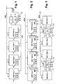
- Each of these four strands has one complete system with coldbox, main heat exchanger, rectification system, lines, Machines and valves on.
- all four are cryogenic air separation plants constructed identically in their interior.
- the rectification system each preferably consists of two columns, a high-pressure column and a Low-pressure column, which has a main condenser in heat exchanging connection stand.
- Each of the four cryogenic air separation plants has its own Pump set P1 to P4.
- Each pump set has three separate ones in the examples Pumps on the liquid oxygen (“liquid product stream”) from the Low pressure column of the respective strand are fed.
- Each of these pumps has a nominal throughput, which is half of the nominal product quantity corresponds internally compressed oxygen of the respective strand.
- each pump set is with the main heat exchanger system of respective cryogenic air separation plant connected. There it will be on high Pressure pumped oxygen either vaporized in the known way and heated (at subcritical pressure) or warmed (at supercritical pressure) and finally via the lines G1 to G4 as gaseous pressure product (GOX-gaseous oxygen) deducted.
- gaseous pressure product GOX-gaseous oxygen
- a heat transfer fluid is a part of the feed air, High pressure nitrogen or another suitable fluid used.
- a portion of the liquid oxygen from the Low-pressure columns of the four cryogenic air separation plants not the Pump sets P1 supplied to P4, but via the lines L1 to L4 as Liquid product (LOX - liquid oxygen) deducted.
- This liquid is in the Example of Figure 1 in a double oxygen tank T1 / T2 trained Liquid reservoir directed, part of an emergency system (backup system) is.
- the emergency supply system also has another pump set P5 and a steam-heated water bath evaporator V on. If one or more of the Cryogenic air separation plants wholly or partially off, is the missing GOX product quantity supplemented by evaporation of liquid oxygen in the Backup System.
- At least one of the lines TL1 or TL2 is closed.
- the corresponding amount of high-pressure oxygen then flows to the Water bath evaporator V1 "and thus ensures the emergency supply.
Landscapes
- Engineering & Computer Science (AREA)
- Physics & Mathematics (AREA)
- Mechanical Engineering (AREA)
- Thermal Sciences (AREA)
- General Engineering & Computer Science (AREA)
- Separation By Low-Temperature Treatments (AREA)
Abstract
Description
Claims (14)
- Verfahren zur Tieftemperaturzerlegung von Luft, bei demein erster Einsatzluftstrom einer ersten Tieftemperatur-Luftzerlegungsanlage, die mindestens eine Trennsäule aufweist, zugeführt wird,ein zweiter Einsatzluftstrom einer zweiten Tieftemperatur-Luftzerlegungsanlage, die mindestens eine Trennsäule aufweist, zugeführt wird,mindestens ein erster Prozess-Strom, welcher der ersten Tieftemperatur-Luftzerlegungsanlage, zugeordnet ist und mindestens ein zweiter Prozess-Strom, welcher der zweiten Tieftemperatur-Luftzerlegungsanlage zugeordnet ist, einem gleichartigen Verfahrensschritt unterzogen werden undder erste und der zweite Prozess-Strom mindestens durch mindestens einen Teilstrom der Einsatzluft, eines Produktstroms oder eines Zwischenproduktstroms der ersten beziehungsweise zweiten Tieftemperatur-Luftzerlegungsanlage gebildet werden, dadurch gekennzeichnet, dassdie beiden Ströme gemeinsam dem gleichartigen Verfahrensschritt zugeleitet werden.
- Verfahren nach Anspruch 1, dadurch gekennzeichnet, dass der gleichartige Verfahrensschritt durch mindestens einen der folgenden Schritte gebildet wird:gemeinsame Verdichtung mindestens eines Teils der Einsatzluft für die erste und die zweite Tieftemperatur-Luftzerlegungsanlage,gemeinsame Vorkühlung mindestens eines Teils der Einsatzluft für die erste und die zweite Tieftemperatur-Luftzerlegungsanlage stromabwärts einer gemeinsamen oder getrennten Verdichtung,gemeinsame adsorptive Reinigung mindestens eines Teils der Einsatzluft für die erste und die zweite Tieftemperatur-Luftzerlegungsanlage,gemeinsame Nachverdichtung mindestens eines Teils der Einsatzluft für die erste und die zweite Tieftemperatur-Luftzerlegungsanlage stromabwärts einer gemeinsamen oder getrennten Verdichtung,gemeinsame Verdichtung je eines Produkt- oder Zwischenproduktstroms aus der ersten beziehungsweise zweiten Tieftemperatur-Luftzerlegungsanlage, der als Kreislaufstrom geführt wird,gemeinsame Druckerhöhung im flüssigen Zustand je eines Produkt- oder Zwischenproduktstroms aus der ersten beziehungsweise zweiten Tieftemperatur-Luftzerlegungsanlage,Einführung je eines Flüssigproduktstroms aus der ersten beziehungsweise zweiten Tieftemperatur-Luftzerlegungsanlage in einen gemeinsamen Tank,Verdampfung je eines Flüssigproduktstroms aus der ersten beziehungsweise zweiten Tieftemperatur-Luftzerlegungsanlage in einem gemeinsamen Verdampfer,Abkühlung von Einsatzluft für die erste und die zweite Tieftemperatur-Luftzerlegungsanlage in einem gemeinsamen Hauptwärmetauscher.
- Verfahren zur Erzeugung eines gasförmigen Druckprodukts durch Tieftemperaturzerlegung von Luft, bei demein erster Einsatzluftstrom einer ersten Tieftemperatur-Luftzerlegungsanlage, die mindestens eine Trennsäule aufweist, zugeführt wird,ein zweiter Einsatzluftstrom einer zweiten Tieftemperatur-Luftzerlegungsanlage, die mindestens eine Trennsäule aufweist, zugeführt wird,ein erster Flüssigproduktstrom aus einer Trennsäule der ersten Tieftemperatur-Luftzerlegungsanlage entnommen, in flüssigem Zustand auf einen erhöhten Druck gebracht und durch indirekten Wärmeaustausch mit einem Wärmeträger-Fluid verdampft und/oder angewärmt und anschließend als ein erster Teil des gasförmigen Druckprodukts gewonnen wird,ein zweiter Flüssigproduktstrom aus einer Trennsäule der zweiten Tieftemperatur-Luftzerlegungsanlage entnommen, in flüssigem Zustand auf einen erhöhten Druck gebracht und durch indirekten Wärmeaustausch mit einem Wärmeträger-Fluid verdampft und/oder angewärmt und anschließend als ein zweiter Teil des gasförmigen Druckprodukts gewonnen wird,
dadurch gekennzeichnet, dassder erste und der zweite Flüssigproduktstrom vor der Druckerhöhung mindestens teilweise vermischt werden. - Verfahren nach Anspruch 3, dadurch gekennzeichnet, dassder erste Flüssigproduktstrom über eine erste Flüssigproduktleitung aus der Trennsäule der ersten Tieftemperatur-Luftzerlegungsanlage abgezogen wird,der zweite Flüssigproduktstrom über eine zweite Flüssigproduktleitung aus der Trennsäule der ersten Tieftemperatur-Luftzerlegungsanlage abgezogen wird,die erste und die zweite Flüssigproduktleitung in eine Gesamtproduktleitung einmünden undder erste und der zweite Flüssigproduktstrom gemeinsam über die Gesamtproduktleitung zur Druckerhöhung im flüssigen Zustand geführt werden.
- Verfahren nach Anspruch 3, dadurch gekennzeichnet, dass der erste und der zweite Flüssigproduktstrom in ein gemeinsames Flüssigkeitsreservoir eingeleitet und von dem Flüssigkeitsreservoir aus der Druckerhöhung im flüssigen Zustand zugeführt werden.
- Verfahren nach Anspruch 5, dadurch gekennzeichnet, dass ein Notversorgungssystem zur Verdampfung von Flüssigprodukt aus dem Flüssigkeitsreservoir unabhängig von dem indirekten Wärmeaustausch mit dem Wärmeträger-Fluid vorgesehen ist, wobei dieses Notversorgungssystem über eine stromabwärts der Druckerhöhung im flüssigen Zustand angeordnete Verzweigung mit Flüssigprodukt beschickbar ist.
- Verfahren nach einem der Ansprüche 3 bis 6, dadurch gekennzeichnet, dassaus dem gemeinsamen Produktstrom stromabwärts der Druckerhöhung im flüssigen Zustand ein erster Teilstrom und ein zweiter Teilstrom abgezweigt werden,der erste Teilstrom in indirekten Wärmeaustausch mit einem ersten Wärmeträger-Fluid-Strom gebracht wird, der stromabwärts des indirekten Wärmeaustauschs mindestens teilweise in eine Trennsäule der ersten Tieftemperatur-Luftzerlegungsanlage eingeleitet wird undder zweite Teilstrom in indirekten Wärmeaustausch mit einem zweiten Wärmeträger-Fluid-Strom gebracht wird, der stromabwärts des indirekten Wärmeaustauschs mindestens teilweise in eine Trennsäule der zweiten Tieftemperatur-Luftzerlegungsanlage eingeleitet wird.
- Verfahren nach einem der Ansprüche 3 bis 7, dadurch gekennzeichnet, dassder gemeinsame Produktstrom stromabwärts der Druckerhöhung im flüssigen Zustand mindestens teilweise in indirekten Wärmeaustausch mit einem gemeinsamen Wärmeträger-Fluid-Strom gebracht wird,ein erster Teil des gemeinsamen Wärmeträger-Fluid-Stroms stromabwärts des indirekten Wärmeaustauschs in eine Trennsäule der ersten Tieftemperatur-Luftzerlegungsanlage eingeleitet wird undein zweiter Teil des gemeinsamen Wärmeträger-Fluid-Stroms stromabwärts des indirekten Wärmeaustauschs in eine Trennsäule der zweiten Tieftemperatur-Luftzerlegungsanlage eingeleitet wird.
- Vorrichtung zur Erzeugung eines gasförmigen Druckprodukts durch Tieftemperaturzerlegung von Luft, miteiner ersten Tieftemperatur-Luftzerlegungsanlage, die mit einer ersten Einsatzluftleitung verbunden ist und mindestens eine Trennsäule aufweist,einer zweiten Tieftemperatur-Luftzerlegungsanlage, die mit einer zweiten Einsatzluftleitung verbunden ist und mindestens eine Trennsäule aufweist,einer ersten Flüssigproduktleitung zur Entnahme eines Flüssigprodukts aus einer Trennsäule der ersten Tieftemperatur-Luftzerlegungsanlage, wobei die erste Flüssigproduktleitung über Mittel zur Druckerhöhung im flüssigen Zustand mit einem Wärmetauscher zur Verdampfung und/oder Anwärmung des flüssig auf einen erhöhten Druck gebrachten Produktstroms durch indirekten Wärmeaustausch mit einem Wärmeträger-Fluid verbunden ist,einer zweiten Flüssigproduktleitung zur Entnahme eines Flüssigprodukts aus einer Trennsäule der zweiten Tieftemperatur-Luftzerlegungsanlage, wobei die zweite Flüssigproduktleitung über Mittel zur Druckerhöhung im flüssigen Zustand mit einem Wärmetauscher zur Verdampfung und/oder Anwärmung des flüssig auf einen erhöhten Druck gebrachten Produktstroms durch indirekten Wärmeaustausch mit einem Wärmeträger-Fluid verbunden ist,
dadurch gekennzeichnet, dassdie erste und die zweite Flüssigproduktleitung mit denselben Mitteln zur Druckerhöhung verbunden sind. - Vorrichtung nach Anspruch 9, dadurch gekennzeichnet, dass die erste und die zweite Flüssigproduktleitung in eine Gesamtproduktleitung einmünden und über diese Gesamtproduktleitung mit dem Eintritt der Mittel zur Druckerhöhung verbunden sind.
- Vorrichtung nach Anspruch 9, dadurch gekennzeichnet, dass die erste und die zweite Flüssigproduktleitung mit einem gemeinsamen Flüssigkeitsreservoir verbunden sind und dass das Flüssigkeitsreservoir über eine weitere Flüssigleitung mit dem Eintritt der Mittel zur Druckerhöhung verbunden ist.
- Vorrichtung nach einem der Ansprüche 9 bis 11, gekennzeichnet durch ein Notversorgungssystem mit Mitteln zur Verdampfung von Flüssigprodukt aus dem Flüssigkeitsreservoir unabhängig von dem indirekten Wärmeaustausch mit dem Wärmeträger-Fluid, wobei dieses Notversorgungssystem mit dem Austritt der Mittel zur Druckerhöhung im flüssigen Zustand verbindbar ist.
- Vorrichtung nach einem der Ansprüche 9 bis 12, dadurch gekennzeichnet, dassder Austritt der Mittel zur Druckerhöhung mit einer ersten und mit einer zweiten Teilstromleitung verbunden ist,die erste Teilstromleitung zu Mitteln zum indirekten Wärmeaustausch mit einem ersten Wärmeträger-Fluid-Strom führt und Mittel zur Einleitung des ersten Wärmeträger-Fluid-Stroms stromabwärts des indirekten Wärmeaustauschs in eine Trennsäule der ersten Tieftemperatur-Luftzerlegungsanlage vorgesehen sind, unddie zweite Teilstromleitung zu Mitteln zum indirekten Wärmeaustausch mit einem zweiten Wärmeträger-Fluid-Strom führt und Mittel zur Einleitung des ersten Wärmeträger-Fluid-Stroms stromabwärts des indirekten Wärmeaustauschs in eine Trennsäule der zweiten Tieftemperatur-Luftzerlegungsanlage vorgesehen sind.
- Vorrichtung nach einem der Ansprüche 9 bis 13, dadurch gekennzeichnet, dassder Austritt der Mittel zur Druckerhöhung mit einer gemeinsamen Produktstromleitung verbunden ist,die gemeinsame Produktstromleitung zu Mitteln zum indirekten Wärmeaustausch mit einem gemeinsamen Wärmeträger-Fluid-Strom führt undsowohl Mittel zur Einleitung eines Teils des gemeinsamen Wärmeträger-Fluid-Stroms stromabwärts des indirekten Wärmeaustauschs in eine Trennsäule der ersten Tieftemperatur-Luftzerlegungsanlage als auch Mittel zur Einleitung eines Teils des gemeinsamen Wärmeträger-Fluid-Stroms stromabwärts des indirekten Wärmeaustauschs in eine Trennsäule der zweiten Tieftemperatur-Luftzerlegungsanlage vorgesehen sind.
Applications Claiming Priority (4)
| Application Number | Priority Date | Filing Date | Title |
|---|---|---|---|
| DE10360297 | 2003-12-20 | ||
| DE10360297 | 2003-12-20 | ||
| DE10406283 | 2004-02-09 | ||
| DE10406283 | 2004-02-09 |
Publications (1)
| Publication Number | Publication Date |
|---|---|
| EP1544559A1 true EP1544559A1 (de) | 2005-06-22 |
Family
ID=34524088
Family Applications (1)
| Application Number | Title | Priority Date | Filing Date |
|---|---|---|---|
| EP04005171A Withdrawn EP1544559A1 (de) | 2003-12-20 | 2004-03-04 | Verfahren und Vorrichtung zur Tieftemperaturzerlegung von Luft |
Country Status (1)
| Country | Link |
|---|---|
| EP (1) | EP1544559A1 (de) |
Cited By (22)
| Publication number | Priority date | Publication date | Assignee | Title |
|---|---|---|---|---|
| US20100071412A1 (en) * | 2008-09-22 | 2010-03-25 | David Ross Parsnick | Method and apparatus for producing high purity oxygen |
| WO2010030427A3 (en) * | 2008-09-10 | 2010-09-16 | Praxair Technology, Inc. | Air separation refrigeration supply method |
| DE102009034979A1 (de) | 2009-04-28 | 2010-11-04 | Linde Aktiengesellschaft | Verfahren und Vorrichtung zur Erzeugung von gasförmigem Drucksauerstoff |
| EP2312248A1 (de) | 2009-10-07 | 2011-04-20 | Linde Aktiengesellschaft | Verfahren und Vorrichtung Gewinnung von Drucksauerstoff und Krypton/Xenon |
| EP2458311A1 (de) | 2010-11-25 | 2012-05-30 | Linde Aktiengesellschaft | Verfahren und Vorrichtung zur Gewinnung eines gasförmigen Druckprodukts durch Tieftemperaturzerlegung von Luft |
| DE102010052544A1 (de) | 2010-11-25 | 2012-05-31 | Linde Ag | Verfahren zur Gewinnung eines gasförmigen Druckprodukts durch Tieftemperaturzerlegung von Luft |
| EP2520886A1 (de) | 2011-05-05 | 2012-11-07 | Linde AG | Verfahren und Vorrichtung zur Erzeugung eines gasförmigen Sauerstoff-Druckprodukts durch Tieftemperaturzerlegung von Luft |
| EP2568242A1 (de) | 2011-09-08 | 2013-03-13 | Linde Aktiengesellschaft | Verfahren und Vorrichtung zur Gewinnung von Stahl |
| EP2600090A1 (de) | 2011-12-01 | 2013-06-05 | Linde Aktiengesellschaft | Verfahren und Vorrichtung zur Erzeugung von Drucksauerstoff durch Tieftemperaturzerlegung von Luft |
| DE102011121314A1 (de) | 2011-12-16 | 2013-06-20 | Linde Aktiengesellschaft | Verfahren zur Erzeugung eines gasförmigen Sauerstoff-Druckprodukts durch Tieftemperaturzerlegung von Luft |
| DE102013017590A1 (de) | 2013-10-22 | 2014-01-02 | Linde Aktiengesellschaft | Verfahren zur Gewinnung eines Krypton und Xenon enthaltenden Fluids und hierfür eingerichtete Luftzerlegungsanlage |
| EP2784420A1 (de) | 2013-03-26 | 2014-10-01 | Linde Aktiengesellschaft | Verfahren zur Luftzerlegung und Luftzerlegungsanlage |
| WO2014154339A2 (de) | 2013-03-26 | 2014-10-02 | Linde Aktiengesellschaft | Verfahren zur luftzerlegung und luftzerlegungsanlage |
| EP2801777A1 (de) | 2013-05-08 | 2014-11-12 | Linde Aktiengesellschaft | Luftzerlegungsanlage mit Hauptverdichterantrieb |
| WO2011071658A3 (en) * | 2009-12-10 | 2015-01-22 | Praxair Technology, Inc. | Oxygen production method and apparatus for enhancing the process capacity |
| EP2865978A1 (de) * | 2013-10-25 | 2015-04-29 | Linde Aktiengesellschaft | Verfahren zur Tieftemperaturzerlegung von Luft und Tieftemperatur-Luftzerlegungsanlage |
| WO2014173496A3 (de) * | 2013-04-25 | 2015-08-20 | Linde Aktiengesellschaft | Verfahren zur gewinnung eines luftprodukts in einer luftzerlegungsanlage mit zwischenspeicherung und luftzerlegungsanlage |
| EP2963367A1 (de) | 2014-07-05 | 2016-01-06 | Linde Aktiengesellschaft | Verfahren und Vorrichtung zur Tieftemperaturzerlegung von Luft mit variablem Energieverbrauch |
| EP2963369A1 (de) | 2014-07-05 | 2016-01-06 | Linde Aktiengesellschaft | Verfahren und vorrichtung zur tieftemperaturzerlegung von luft |
| EP2963370A1 (de) | 2014-07-05 | 2016-01-06 | Linde Aktiengesellschaft | Verfahren und vorrichtung zur tieftemperaturzerlegung von luft |
| EP2963371A1 (de) | 2014-07-05 | 2016-01-06 | Linde Aktiengesellschaft | Verfahren und vorrichtung zur gewinnung eines druckgasprodukts durch tieftemperaturzerlegung von luft |
| WO2017127136A1 (en) | 2016-01-22 | 2017-07-27 | Praxair Technology, Inc. | Method and system for providing auxiliary refrigeration to an air separation plant |
Citations (8)
| Publication number | Priority date | Publication date | Assignee | Title |
|---|---|---|---|---|
| US5596885A (en) * | 1994-06-20 | 1997-01-28 | L'air Liquide, Societe Anonyme Pour L'etude Et L'exploitation Des Procedes Georges Claude | Process and installation for the production of gaseous oxygen under pressure |
| US5896755A (en) * | 1998-07-10 | 1999-04-27 | Praxair Technology, Inc. | Cryogenic rectification system with modular cold boxes |
| US6128921A (en) * | 1998-02-06 | 2000-10-10 | L'air Liquide | Air distillation plant comprising a plurality of cryogenic distillation units of the same type |
| EP1043558A2 (de) * | 1999-04-05 | 2000-10-11 | L'air Liquide, Societe Anonyme Pour L'etude Et L'exploitation Des Procedes Georges Claude | Integrierte Anlage zur Energie- und/oder Sauerstoffreichflüssigkeiterzeugung und deren Verfahren |
| US6550234B2 (en) * | 2001-01-12 | 2003-04-22 | L'air Liquide Societe Anonyme A Directoire Et Conseil De Surveillance Pour L'etude Et L'exploitation Des Procedes Georges Claude | Integrated air-separation/energy-generation process and plant for implementing such a process |
| FR2831953A1 (fr) * | 2001-11-05 | 2003-05-09 | Air Liquide | Procede de distillation d'air avec production d'argon et installation de distillation d'air correspondante |
| EP1398585A1 (de) * | 2002-09-11 | 2004-03-17 | L'air liquide, Société anonyme à Directoire et Conseil de Surveillance pour l'Etude et l'Exploitation des Procédés G. Claude | Vorrichtung zur Gewinnung von Sauerstoff und/oder Stickstoff in grossen Mengen |
| EP1435497A2 (de) * | 2002-11-01 | 2004-07-07 | L'AIR LIQUIDE, Société Anonyme à Directoire et Conseil de Surveillance pour l'Etude et l'Exploitation des | Kombinierte Vorrichtung zur Luftzerlegung und Erdgasverflüssigung |
-
2004
- 2004-03-04 EP EP04005171A patent/EP1544559A1/de not_active Withdrawn
Patent Citations (8)
| Publication number | Priority date | Publication date | Assignee | Title |
|---|---|---|---|---|
| US5596885A (en) * | 1994-06-20 | 1997-01-28 | L'air Liquide, Societe Anonyme Pour L'etude Et L'exploitation Des Procedes Georges Claude | Process and installation for the production of gaseous oxygen under pressure |
| US6128921A (en) * | 1998-02-06 | 2000-10-10 | L'air Liquide | Air distillation plant comprising a plurality of cryogenic distillation units of the same type |
| US5896755A (en) * | 1998-07-10 | 1999-04-27 | Praxair Technology, Inc. | Cryogenic rectification system with modular cold boxes |
| EP1043558A2 (de) * | 1999-04-05 | 2000-10-11 | L'air Liquide, Societe Anonyme Pour L'etude Et L'exploitation Des Procedes Georges Claude | Integrierte Anlage zur Energie- und/oder Sauerstoffreichflüssigkeiterzeugung und deren Verfahren |
| US6550234B2 (en) * | 2001-01-12 | 2003-04-22 | L'air Liquide Societe Anonyme A Directoire Et Conseil De Surveillance Pour L'etude Et L'exploitation Des Procedes Georges Claude | Integrated air-separation/energy-generation process and plant for implementing such a process |
| FR2831953A1 (fr) * | 2001-11-05 | 2003-05-09 | Air Liquide | Procede de distillation d'air avec production d'argon et installation de distillation d'air correspondante |
| EP1398585A1 (de) * | 2002-09-11 | 2004-03-17 | L'air liquide, Société anonyme à Directoire et Conseil de Surveillance pour l'Etude et l'Exploitation des Procédés G. Claude | Vorrichtung zur Gewinnung von Sauerstoff und/oder Stickstoff in grossen Mengen |
| EP1435497A2 (de) * | 2002-11-01 | 2004-07-07 | L'AIR LIQUIDE, Société Anonyme à Directoire et Conseil de Surveillance pour l'Etude et l'Exploitation des | Kombinierte Vorrichtung zur Luftzerlegung und Erdgasverflüssigung |
Non-Patent Citations (1)
| Title |
|---|
| SCHARLE W J ET AL: "OXYGEN FACILITIES FOR SYNTHETIC FUEL PROJECTS", TRANSACTIONS OF THE AMERICAN SOCIETY OF MECHANICAL ENGINEERS, SERIES B: JOURNAL OF ENGINEERING FOR INDUSTRY, ASME. NEW YORK, US, vol. 103, November 1981 (1981-11-01), pages 409 - 417, XP009026023, ISSN: 0022-0817 * |
Cited By (29)
| Publication number | Priority date | Publication date | Assignee | Title |
|---|---|---|---|---|
| WO2010030427A3 (en) * | 2008-09-10 | 2010-09-16 | Praxair Technology, Inc. | Air separation refrigeration supply method |
| US9714789B2 (en) | 2008-09-10 | 2017-07-25 | Praxair Technology, Inc. | Air separation refrigeration supply method |
| US8479535B2 (en) * | 2008-09-22 | 2013-07-09 | Praxair Technology, Inc. | Method and apparatus for producing high purity oxygen |
| US20100071412A1 (en) * | 2008-09-22 | 2010-03-25 | David Ross Parsnick | Method and apparatus for producing high purity oxygen |
| DE102009034979A1 (de) | 2009-04-28 | 2010-11-04 | Linde Aktiengesellschaft | Verfahren und Vorrichtung zur Erzeugung von gasförmigem Drucksauerstoff |
| EP2312248A1 (de) | 2009-10-07 | 2011-04-20 | Linde Aktiengesellschaft | Verfahren und Vorrichtung Gewinnung von Drucksauerstoff und Krypton/Xenon |
| WO2011071658A3 (en) * | 2009-12-10 | 2015-01-22 | Praxair Technology, Inc. | Oxygen production method and apparatus for enhancing the process capacity |
| EP2458311A1 (de) | 2010-11-25 | 2012-05-30 | Linde Aktiengesellschaft | Verfahren und Vorrichtung zur Gewinnung eines gasförmigen Druckprodukts durch Tieftemperaturzerlegung von Luft |
| DE102010052545A1 (de) | 2010-11-25 | 2012-05-31 | Linde Aktiengesellschaft | Verfahren und Vorrichtung zur Gewinnung eines gasförmigen Druckprodukts durch Tieftemperaturzerlegung von Luft |
| DE102010052544A1 (de) | 2010-11-25 | 2012-05-31 | Linde Ag | Verfahren zur Gewinnung eines gasförmigen Druckprodukts durch Tieftemperaturzerlegung von Luft |
| EP2466236A1 (de) | 2010-11-25 | 2012-06-20 | Linde Aktiengesellschaft | Verfahren zur Gewinnung eines gasförmigen Druckprodukts durch Tiefemperaturzerlegung von Luft |
| EP2520886A1 (de) | 2011-05-05 | 2012-11-07 | Linde AG | Verfahren und Vorrichtung zur Erzeugung eines gasförmigen Sauerstoff-Druckprodukts durch Tieftemperaturzerlegung von Luft |
| DE102011112909A1 (de) | 2011-09-08 | 2013-03-14 | Linde Aktiengesellschaft | Verfahren und Vorrichtung zur Gewinnung von Stahl |
| EP2568242A1 (de) | 2011-09-08 | 2013-03-13 | Linde Aktiengesellschaft | Verfahren und Vorrichtung zur Gewinnung von Stahl |
| EP2600090A1 (de) | 2011-12-01 | 2013-06-05 | Linde Aktiengesellschaft | Verfahren und Vorrichtung zur Erzeugung von Drucksauerstoff durch Tieftemperaturzerlegung von Luft |
| DE102011121314A1 (de) | 2011-12-16 | 2013-06-20 | Linde Aktiengesellschaft | Verfahren zur Erzeugung eines gasförmigen Sauerstoff-Druckprodukts durch Tieftemperaturzerlegung von Luft |
| EP2784420A1 (de) | 2013-03-26 | 2014-10-01 | Linde Aktiengesellschaft | Verfahren zur Luftzerlegung und Luftzerlegungsanlage |
| WO2014154339A2 (de) | 2013-03-26 | 2014-10-02 | Linde Aktiengesellschaft | Verfahren zur luftzerlegung und luftzerlegungsanlage |
| US10533795B2 (en) | 2013-04-25 | 2020-01-14 | Linde Aktiengesellschaft | Method for obtaining an air product in an air separating system with temporary storage, and air separating system |
| WO2014173496A3 (de) * | 2013-04-25 | 2015-08-20 | Linde Aktiengesellschaft | Verfahren zur gewinnung eines luftprodukts in einer luftzerlegungsanlage mit zwischenspeicherung und luftzerlegungsanlage |
| EP2801777A1 (de) | 2013-05-08 | 2014-11-12 | Linde Aktiengesellschaft | Luftzerlegungsanlage mit Hauptverdichterantrieb |
| DE102013017590A1 (de) | 2013-10-22 | 2014-01-02 | Linde Aktiengesellschaft | Verfahren zur Gewinnung eines Krypton und Xenon enthaltenden Fluids und hierfür eingerichtete Luftzerlegungsanlage |
| EP2865978A1 (de) * | 2013-10-25 | 2015-04-29 | Linde Aktiengesellschaft | Verfahren zur Tieftemperaturzerlegung von Luft und Tieftemperatur-Luftzerlegungsanlage |
| EP2963369A1 (de) | 2014-07-05 | 2016-01-06 | Linde Aktiengesellschaft | Verfahren und vorrichtung zur tieftemperaturzerlegung von luft |
| EP2963370A1 (de) | 2014-07-05 | 2016-01-06 | Linde Aktiengesellschaft | Verfahren und vorrichtung zur tieftemperaturzerlegung von luft |
| EP2963371A1 (de) | 2014-07-05 | 2016-01-06 | Linde Aktiengesellschaft | Verfahren und vorrichtung zur gewinnung eines druckgasprodukts durch tieftemperaturzerlegung von luft |
| WO2016005031A1 (de) | 2014-07-05 | 2016-01-14 | Linde Aktiengesellschaft | Verfahren und vorrichtung zur tieftemperaturzerlegung von luft mit variablem energieverbrauch |
| EP2963367A1 (de) | 2014-07-05 | 2016-01-06 | Linde Aktiengesellschaft | Verfahren und Vorrichtung zur Tieftemperaturzerlegung von Luft mit variablem Energieverbrauch |
| WO2017127136A1 (en) | 2016-01-22 | 2017-07-27 | Praxair Technology, Inc. | Method and system for providing auxiliary refrigeration to an air separation plant |
Similar Documents
| Publication | Publication Date | Title |
|---|---|---|
| EP2235460B1 (de) | Verfahren und vorrichtung zur tieftemperatur-luftzerlegung | |
| EP1994344A1 (de) | Vefahren und vorrichtung zur tieftemperaturzerlegung von luft | |
| DE102010052544A1 (de) | Verfahren zur Gewinnung eines gasförmigen Druckprodukts durch Tieftemperaturzerlegung von Luft | |
| DE102010052545A1 (de) | Verfahren und Vorrichtung zur Gewinnung eines gasförmigen Druckprodukts durch Tieftemperaturzerlegung von Luft | |
| EP1150082A1 (de) | Verfahren und Vorrichtung zum Wärmeaustausch | |
| EP2236964A1 (de) | Verfahren und Vorrichtung zur Tieftemperatur-Luftzerlegung | |
| WO2016131545A1 (de) | Verfahren und vorrichtung zur gewinnung eines druckstickstoffprodukts | |
| DE10013073A1 (de) | Verfahren und Vorrichtung zur Tieftemperaturzerlegung von Luft | |
| EP0895045A2 (de) | Verfahren zur Luftzerlegung | |
| DE10334560A1 (de) | Verfahren und Vorrichtung zur Gewinnung von Krypton und/oder Xenon durch Tieftemperaturzerlegung von Luft | |
| DE10228111A1 (de) | Luftzerlegungsverfahren und -anlage mit Mischsäule und Krypton-Xenon-Gewinnung | |
| DE102010056560A1 (de) | Verfahren und Vorrichtung zur Gewinnung von Drucksauerstoff und Druckstickstoff durch Tieftemperaturzerlegung von Luft | |
| DE102005029274A1 (de) | Verfahren und Vorrichtung zur Gewinnung eines gasförmigen Druckprodukts durch Tieftemperatur-Zerlegung von Luft | |
| EP2489968A1 (de) | Verfahren und Vorrichtung zur Tieftemperaturzerlegung von Luft | |
| EP3410050A1 (de) | Verfahren zur gewinnung eines oder mehrerer luftprodukte und luftzerlegungsanlage | |
| DE102018000842A1 (de) | Verfahren und Vorrichtung zur Gewinnung von Druckstickstoff durch Tieftemperaturzerlegung von Luft | |
| DE10213212A1 (de) | Verfahren und Vorrichtung zur Erzeugung zweier Druckprodukte durch Tieftemperatur-Luftzerlegung | |
| EP3207320A1 (de) | Verfahren und vorrichtung zur variablen gewinnung von argon durch tieftemperaturzerlegung | |
| EP0768503A2 (de) | Dreifachsäulenverfahren zur Tieftemperaturzerlegung von Luft | |
| DE102007042462A1 (de) | Verfahren und Vorrichtung zur Tieftemperaturzerlegung von Luft | |
| DE10209421A1 (de) | Verfahren und Vorrichtung zur Gewinnung eines Druckprodukts durch Tieftemperaturzerlegung von Luft | |
| DE19933558B4 (de) | Dreisäulenverfahren und -vorrichtung zur Tieftemperaturzerlegung von Luft | |
| EP4065910A1 (de) | Verfahren und anlage zur tieftemperaturzerlegung von luft | |
| DE102004016931A1 (de) | Verfahren und Vorrichtung zur variablen Erzeugung eines Druckproduktes durch Tieftemperaturzerlegung von Luft | |
| EP3067650A1 (de) | Anlage und verfahren zur erzeugung von sauerstoff durch tieftemperaturzerlegung von luft |
Legal Events
| Date | Code | Title | Description |
|---|---|---|---|
| PUAI | Public reference made under article 153(3) epc to a published international application that has entered the european phase |
Free format text: ORIGINAL CODE: 0009012 |
|
| AK | Designated contracting states |
Kind code of ref document: A1 Designated state(s): AT BE BG CH CY CZ DE DK EE ES FI FR GB GR HU IE IT LI LU MC NL PL PT RO SE SI SK TR |
|
| AX | Request for extension of the european patent |
Extension state: AL LT LV MK |
|
| 17P | Request for examination filed |
Effective date: 20051124 |
|
| AKX | Designation fees paid |
Designated state(s): AT BE BG CH CY CZ DE DK EE ES FI FR GB GR HU IE IT LI LU MC NL PL PT RO SE SI SK TR |
|
| 17Q | First examination report despatched |
Effective date: 20070620 |
|
| RAP1 | Party data changed (applicant data changed or rights of an application transferred) |
Owner name: LINDE AKTIENGESELLSCHAFT |
|
| RAP1 | Party data changed (applicant data changed or rights of an application transferred) |
Owner name: LINDE AG |
|
| STAA | Information on the status of an ep patent application or granted ep patent |
Free format text: STATUS: THE APPLICATION IS DEEMED TO BE WITHDRAWN |
|
| 18D | Application deemed to be withdrawn |
Effective date: 20111001 |