EP1544603A2 - Capteur de gaz - Google Patents
Capteur de gaz Download PDFInfo
- Publication number
- EP1544603A2 EP1544603A2 EP04255341A EP04255341A EP1544603A2 EP 1544603 A2 EP1544603 A2 EP 1544603A2 EP 04255341 A EP04255341 A EP 04255341A EP 04255341 A EP04255341 A EP 04255341A EP 1544603 A2 EP1544603 A2 EP 1544603A2
- Authority
- EP
- European Patent Office
- Prior art keywords
- gas sensor
- sensor
- detector
- gas
- output
- Prior art date
- Legal status (The legal status is an assumption and is not a legal conclusion. Google has not performed a legal analysis and makes no representation as to the accuracy of the status listed.)
- Granted
Links
Images




Classifications
-
- G—PHYSICS
- G01—MEASURING; TESTING
- G01N—INVESTIGATING OR ANALYSING MATERIALS BY DETERMINING THEIR CHEMICAL OR PHYSICAL PROPERTIES
- G01N21/00—Investigating or analysing materials by the use of optical means, i.e. using sub-millimetre waves, infrared, visible or ultraviolet light
- G01N21/17—Systems in which incident light is modified in accordance with the properties of the material investigated
- G01N21/25—Colour; Spectral properties, i.e. comparison of effect of material on the light at two or more different wavelengths or wavelength bands
- G01N21/31—Investigating relative effect of material at wavelengths characteristic of specific elements or molecules, e.g. atomic absorption spectrometry
- G01N21/35—Investigating relative effect of material at wavelengths characteristic of specific elements or molecules, e.g. atomic absorption spectrometry using infrared light
- G01N21/3504—Investigating relative effect of material at wavelengths characteristic of specific elements or molecules, e.g. atomic absorption spectrometry using infrared light for analysing gases, e.g. multi-gas analysis
-
- G—PHYSICS
- G01—MEASURING; TESTING
- G01N—INVESTIGATING OR ANALYSING MATERIALS BY DETERMINING THEIR CHEMICAL OR PHYSICAL PROPERTIES
- G01N21/00—Investigating or analysing materials by the use of optical means, i.e. using sub-millimetre waves, infrared, visible or ultraviolet light
- G01N21/01—Arrangements or apparatus for facilitating the optical investigation
- G01N21/03—Cuvette constructions
- G01N21/0303—Optical path conditioning in cuvettes, e.g. windows; adapted optical elements or systems; path modifying or adjustment
-
- G—PHYSICS
- G01—MEASURING; TESTING
- G01N—INVESTIGATING OR ANALYSING MATERIALS BY DETERMINING THEIR CHEMICAL OR PHYSICAL PROPERTIES
- G01N21/00—Investigating or analysing materials by the use of optical means, i.e. using sub-millimetre waves, infrared, visible or ultraviolet light
- G01N21/17—Systems in which incident light is modified in accordance with the properties of the material investigated
- G01N21/25—Colour; Spectral properties, i.e. comparison of effect of material on the light at two or more different wavelengths or wavelength bands
- G01N21/31—Investigating relative effect of material at wavelengths characteristic of specific elements or molecules, e.g. atomic absorption spectrometry
- G01N21/314—Investigating relative effect of material at wavelengths characteristic of specific elements or molecules, e.g. atomic absorption spectrometry with comparison of measurements at specific and non-specific wavelengths
Definitions
- the present invention relates to gas sensors, and in particular to gas sensing devices that detect the presence of a specific gas by monitoring the absorption of optical radiation transmitted through a chamber containing a sample of gas under test.
- Gas sensors utilising an infra-red source and a corresponding infra-red detector are well known, in particular in the design of, for example, carbon dioxide and hydrocarbon gas detectors.
- Infra-red radiation emitted by the source is focussed onto the detector, having passed through a chamber containing the gas under test, where some of the infra-red radiation will be absorbed by the gas.
- the absorption by a specific gas is a function of the wavelength of the infra-red radiation, and by careful selection of an appropriate optical band-pass filter at the detector, it is possible to determine the presence of a specific gas.
- a gas sensor 1 comprises an optical source 2 for emitting radiation in the optical spectrum and a detector 3 for detection of radiation emitted by the source 2.
- the source 2 and detector 3 are respectively located at opposite ends of an optical pathway 4 (figure 2) which pathway is defined by a circumferential chamber 5 and a central chamber 6 respectively defining a generally circumferential portion 4a of the optical pathway 4 and a generally radial portion 4b of the optical pathway.
- the circumferential chamber 5 is defined by: a chamber base 7; an internal surface of an outer cylindrical wall 8 of the sensor housing; an external surface of an inner cylindrical wall 9 of the sensor housing; and a radial end wall 10.
- the central chamber 6 is defined by an internal surface of the housing base 11 and an internal surface of the inner cylindrical wall 9 of the sensor housing.
- the housing base 11 provides a planar reflective surface, in the central chamber 6.
- Optical communication between the circumferential chamber 5 and the central chamber 6 is by way of a gap 12 in the inner cylindrical wall 9.
- a deflector element 13 provides a reflecting surface 14 which generally extends from the outer cylindrical wall 8 to the inner cylindrical wall 9.
- the top 16 of the sensor housing includes a gas permeable window 17 to allow controlled diffusion of gas under test from the external ambient of the sensor housing to the optical pathway 4 in the chambers 5 and 6.
- the gas permeable window 17 typically comprises a disc shaped element of sintered flame arresting material that allows diffusion of gas but forms a combustion barrier so that the source 2 cannot accidentally act as an ignition source when the sensor is operating in a hazardous and combustible gaseous environment.
- the detector 3 is mounted in the base 11 of the sensor housing and comprises a dual element pyroelectric detector.
- the detector elements 3a, 3b are arranged in a spaced relationship along a vertical axis V of the sensor housing, i.e. an axis parallel to the central axis defined by the inner and outer cylindrical walls 8, 9. This axial spacing of the detector elements 3a, 3b ensures that the characteristics of the optical pathways leading to each of the elements are substantially similar.
- Each element 3a, 3b includes a filter (not shown) to allow the transmission of optical radiation at selected frequencies or frequency ranges. This dual element configuration enables the sensor to operate with one reference or compensation detector to increase accuracy of the measurements, as will be described hereinafter.
- the incandescent source 2 emits infra-red radiation over a broad spectrum of frequencies.
- the reflective surfaces formed by the inner and outer cylindrical walls 8, 9 and the radial end wall 10 guide the infra-red radiation around the circumferential chamber 5.
- the non-focussing nature of the reflector surfaces means that positioning of the source 2 within the circumferential chamber 5 is not critical.
- the present invention provides a gas sensor comprising:
- the present invention provides an integrated gas sensor comprising, within a single housing:
- the present invention provides an integrated gas sensor comprising, within a single housing:
- a gas sensor 41 comprises a non-focussed optical source 42 for emitting radiation in the optical spectrum.
- optical is intended to cover all parts of the electromagnetic spectrum that are useful for the function of gas detection by absorption and includes the infra-red, visible, and ultra-violet ranges of the electromagnetic spectrum.
- the source 42 is preferably of the incandescent variety, producing a broad range of frequencies with which to measure absorption characteristics, but may also be of the solid state variety such as diodes producing limited frequencies or frequency bands.
- the gas sensor 41 further comprises a detector 43 for detection of radiation emitted by the source 42.
- the detector 43 may be of any suitable type for sensing variations in intensity of radiation received from the source and providing as output a voltage or current as a function thereof. In a preferred embodiment, operating in the infra-red spectrum, the detector 43 is a pyroelectric detector.
- the source 42 and detector 43 are respectively located at opposite ends of an optical pathway 44 (figures 5 and 6) which pathway is defined by a circumferential chamber 45 and a central chamber 46 respectively defining a generally circumferential portion 44a of the optical pathway 44 and a generally radial portion 44b of the optical pathway.
- the circumferential chamber 45 is defined by: a chamber base 47; an internal surface of an outer cylindrical wall 48 of the sensor housing; an external surface of an inner cylindrical wall 49 of the sensor housing; and a radial end wall 50.
- the chamber base 47 provides a planar reflective surface.
- the chamber base 47 provides a gas-tight fit against the sensor housing outer cylindrical wall 48 by way of an o-ring seal 74.
- the walls of the circumferential chamber 45 are formed from cylindrical walls 48, 49, it will be understood that some departure from smooth convex and concave surfaces is possible, for example using a multifaceted configuration to form generally circumferential walls.
- the circumferential walls 48, 49 could also be concave or convex along the axial direction.
- the radial end wall 50 is preferably planar.
- the central chamber 46 is defined by an internal surface of the housing base 51 and an internal surface of the inner cylindrical wall 49 of the sensor housing.
- the housing base 51 provides a planar reflective surface, in the central chamber 46.
- the curved wall of the central chamber 46 is formed from the inner cylindrical wall 49, it will be understood that some departure from a smooth concave surface is possible, for example using a multifaceted configuration to form the internal surface.
- the internal surface of the inner cylindrical wall 49 could also be concave or convex along the axial direction.
- Optical communication between the circumferential chamber 45 and the central chamber 46 is by way of a gap 52 in the inner cylindrical wall 49.
- a deflector element 53 provides a reflecting surface 54 which generally extends from the outer cylindrical wall 48 to the inner cylindrical wall 49.
- the reflecting surface 54 is preferably planar.
- the reflecting surface 54 is generally oblique to the tangent of the outer and inner circumferential walls 48, 49 at the position of the gap 52, but may also be radial.
- the deflector 53 is preferably formed from a wedge shaped element which also forms the radial end wall 50.
- the wedge shaped element may also be oblique (rather than orthogonal) to the chamber base 47 so that light from the circumferential optical path 44a is directed at least partially upwards.
- the deflector 53 on the wedge shaped element may be comprised of multiple facets each at an oblique angle to the chamber base 47 so that light from the circumferential optical path 44a is directed at least partially upwards.
- the top 56 of the sensor housing includes a gas permeable window 57 to allow controlled diffusion of gas under test from the external ambient of the sensor housing to the optical pathway 44 in the chambers 45 and 46.
- the gas permeable window 57 comprises a disc shaped element of wire mesh forming a flame arrester.
- the flame arrester could alternatively use any flame arresting material that allows diffusion of gas but forms a combustion barrier so that the source 42 cannot accidentally act as an ignition source when the sensor is operating in a hazardous and combustible gaseous environment.
- the disc element 57 has a radius that is greater than the radius of the inner cylindrical wall 49 and less than the radius of the outer cylindrical wall 48 so that the gas permeable window completely extends over the central chamber 46 and partially extends over the circumferential chamber 45.
- the remaining portion 58 of the top 56 of the sensor housing provides a reflective inner surface 59 partially covering the circumferential chamber 45 to enhance the optical transmission characteristics of the circumferential chamber.
- the detector 43 is mounted to the base 51 in the sensor housing and preferably comprises a dual element pyroelectric detector.
- the detector elements 43a, 43b are preferably arranged in a spaced relationship along a horizontal axis H of the sensor housing, i.e. a diametric axis orthogonal to the central axis defined by the inner and outer cylindrical walls 48, 49. This axial spacing of the detector elements 43a, 43b ensures that the characteristics of the optical pathways leading to each of the elements are substantially similar.
- Each element 43a, 43b includes a filter (not shown) to allow the transmission of optical radiation at selected frequencies or frequency ranges. This dual element configuration enables the sensor to operate with one reference or compensation detector to increase accuracy of the measurements, as in known in the art.
- Electrodes 60 to both the source 42 and the detector 43 pass through the housing base 51 and through an encapsulant layer 61 that holds the base 51 in position.
- the encapsulant layer 61 also seals the housing so that it is gas tight except for the controlled diffusion window 57.
- the encapsulant may be protected by way of a closing plate 62.
- the housing of sensor 41 may be made to conform to an industry standard configuration in terms of external dimensions and positioning of a plurality of electrical leads 60, not all of which are shown in the drawings.
- the overall outside casing diameter is approximately 2 cm, and the casing height is approximately 2 cm.
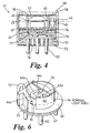
- the diffusion window 57 and encapsulant layer 61 each have a thickness suitable to meet any applicable safety requirements or regulations. More preferably, the overall outside casing diameter is 20 mm ⁇ 0.15 mm and the casing height is 16.6 mm ⁇ 0.15 mm (excluding projecting leads), as shown in figure 4, so as to provide backward compatibility with prior art sensor casing styles.
- a particular feature of the sensor 41 is that the detector 43 is mounted with its detector elements 43a, 43b disposed on the horizontal axis H, and preferably facing upwards.
- An inclined reflector 75 is provided with its reflective surface at an oblique angle to the horizontal axis H and facing the gap 52 so that light from the circumferential path 44a and deflector 53 is directed downwards onto the detector elements 43a, 43b along an at least partially axial optical path 44c.
- the inclined reflector presents its reflective surface at an angle of 45 degrees to the horizontal axis H.
- the incandescent source 42 emits infra-red radiation over a broad spectrum of frequencies.
- the reflective surfaces formed by the inner and outer cylindrical walls 48, 49 and the radial end wall 50 guide the infra-red radiation around the circumferential chamber 45.
- the non-focussing nature of the reflector surfaces means that positioning of the source 42 within the circumferential chamber 45 is not critical.
- the preferred planar geometry of the reflecting surface 54 and reflector 75 is such that the radiation incident upon the detector elements 43a, 43b is principally normal to the elements' surfaces which provides optimum temperature characteristics for the sensor 41 and ensures that a substantially equal amount of radiation falls on both elements 43a, 43b. This provides for better matching conditions between the two detector element outputs.
- the circumferential optical path 44a also utilises the space within the sensor housing in a highly efficient manner, and allows the chamber walls 48, 49 to be formed from cylindrical elements that are easy to manufacture and also easy to assemble.
- the completion of the optical path 44 with the radial portion 44b and axial portion 44c enables the detector to be mounted centrally and with its electrical contact pins directed straight into a printed circuit board 76 with its major dimension lying flat to the printed circuit board.
- the arrangement also facilitates easy positioning of the detector within the central chamber 46.
- the layout of the optical components releases a significant proportion of the sensor housing for signal processing electronics.
- the printed circuit board 76 which includes various electronic components 77.
- these electronic components 77 include a driver circuit 100 for the optical source 42.
- the detector 43 provides two electrical outputs 101, 102 corresponding respectively to the first detector element 43a and the second detector element 43b.
- the first detector element provides a first output signal on line 101 associated with the absorption spectra of the selected gas for detection, eg. carbon monoxide.
- the second detector element provides a second output signal on line 102 associated with a broader spread of frequencies, or preferably a selected bandwidth different from that of the first filter and relatively immune from undesirable attenuation from other common gases, to provide a reference signal.
- the reference signal is used to provide compensation of the attenuation measured by the first sensor that arises from temperature, humidity, degradation of the source intensity and other obscuration factors, rather than from the presence of the selected gas in the optical pathway 44.
- the ratio of the reference and selected gas signals will therefore be substantially unaffected by these other factors.
- the two output signal lines 101, 102 are connected to a pre-amplification circuit 103, the output from which is connected to an analogue-to-digital converter 104 (hereinafter 'ADC').
- the digitised output of the ADC 104 is supplied to a microprocessor 105.
- the microprocessor 105 is provided with a memory module 106 that is used for program storage and for storing look-up tables 107 (hereinafter 'LUT's') required for computing a gas concentration value from the inputs to the microprocessor.
- the microprocessor 105 is also preferably provided with an external programming interface 108 which may be implemented by way of programming contacts 78 as shown in figure 4.
- the microprocessor also includes an output path or driver 109 coupled to the electrical leads 60.
- the output driver 109 includes a digital-to-analogue converter (hereinafter 'DAC') for converting the digital output of the microprocessor 105 to a proportional analogue voltage.
- 'DAC' digital-to-analogue converter
- the output driver 109 may simply comprise an electrical bus.
- the gas sensor 41 is preferably also provided with one or more of suitable temperature, pressure and humidity sensors 110 so that any necessary corrections to the detector 43 readings can be made.
- the ADC 104, or a further ADC provide digitised readings to the microprocessor 105.
- the microprocessor 105 uses the LUT's in order to determine corrections for temperature, pressure and/or humidity, according to the accuracy and application required of the specific gas sensor. Alternatively, these corrections could be made by computation according appropriate formulae, e.g. stored in the microprocessor memory 106. In an alternative configuration, analogue outputs from the temperature, pressure and/or humidity sensors could be used directly to compensate the detector output signals in the analogue domain.
- the various components described in connection with figure 8 are preferably connected to a common power supply (e.g. 5V DC) by way of the external electrical leads 60.
- the output driver 109 is similarly connected to the external electrical leads 60.
- the compensated output is temperature compensated.
- the compensated output is pressure compensated.
- the compensated output is humidity compensated.
- the microprocessor 105 is also configured to calibrate the sensor output so that the sensor output lies within predetermined maximum and minimum end values. This is referred to herein as 'normalisation' of the output. Such normalisation may be useful to offset any gradual degradation in the optical source performance over time.
- the microprocessor 105 is also configured to determine the gas concentration versus voltage output slope to ensure that the gas sensor 41 has a desired output characteristic. This is referred to herein as the 'transfer characteristic'. This is particularly useful where it is desired to use the gas sensors as replacement units for other existing types of gas sensor.
- pellistor-type gas sensors have particular output characteristics and it may be useful to configure the optical gas sensor 41 such that the output characteristic behaves exactly the same as a pellistor output.
- the programming contacts 78 may be used to configure the output characteristics of the sensor 41.
- the same optical sensor 41 may be used in a variety of different applications, as a direct replacement for different types of gas sensor (e.g. non-optical), by first switching the characteristics of the sensor 41 using the programming contacts 60.
- This configuration operation may comprise up-loading predetermined LUT's 107, or selecting an installed LUT for use.
- the configuration operation may be a one-off event, at the point of manufacture, or may be provided as a user function to be done once on installation, or multiple times during operation of the sensor.
- the configuration operation need not be restricted to programming LUT's.
- variables may be altered for use in formulae used to calculate gas concentrations, and programs or sub-routines may be updated.
- the gas permeable window 57 ensures that any changes in gas concentrations external to the sensor housing are rapidly communicated to the optical pathway 44 particularly in the circumferential chamber 45, to be sensed by the detector elements 43a, 43b, providing good real time output of sensed gas conditions.
- the preferred design of gas permeable window 57 as shown ensures that natural diffusion of gas into the circumferential chamber 45 is sufficient so that no pumping of gas through the chamber is required.
- having temperature, pressure and/or humidity sensor located within the housing very close to, or within, the optical chamber housing ensures that changes in environmental conditions are rapidly communicated to the sensor output.
- the preferred embodiment provides the source 42 located at the closed end of the circumferential chamber 45, and the detector 43 located in the central chamber 46, it will be understood that these positions may be reversed.
- the illustrated embodiment shows a gas sensor 41 having an optical path which includes the circumferential portion 44a, the radial portion 44b and an axial downward portion 44c.
- the detector could be inverted and positioned adjacent to the top 56 of the sensor in which case an axial upward portion of the optical pathway would be required. This arrangement would be less preferred as the coupling of the detector 43 to the associated electronic components 77 would be more complex and at least part of the gas permeable window 57 may be occluded.
- the circumferential chamber 45 need not be exactly circular to provide a substantially circular portion of the optical pathway.
- a polygonal package eg. hexagonal
- the circumferential chamber may also be of a spiral configuration, in which the chamber wraps over itself after one complete circuit of the periphery of the chamber.
- some or all of the reflective surfaces may be gold coated (or coated with other suitable reflective material) to enhance signal amplitude, and/or coated with a passivation layer to provide protection against corrosive gases.
- the gas permeable window 57 could also be formed from other materials, such as a gauze screen.
- the gas permeable window 57 need not be disc shaped, but could comprise a series of discrete openings in the top of the housing or be annular in shape.
- the detector 43 need not be of the dual element type if a reference detector is not required. Multiple detector elements, each with an appropriate filter, may be provided for simultaneous detection of more than one selected gas.
Landscapes
- Physics & Mathematics (AREA)
- Spectroscopy & Molecular Physics (AREA)
- Health & Medical Sciences (AREA)
- Life Sciences & Earth Sciences (AREA)
- Chemical & Material Sciences (AREA)
- Analytical Chemistry (AREA)
- Biochemistry (AREA)
- General Health & Medical Sciences (AREA)
- General Physics & Mathematics (AREA)
- Immunology (AREA)
- Pathology (AREA)
- Investigating Or Analysing Materials By Optical Means (AREA)
- Glass Compositions (AREA)
- Investigating Or Analyzing Materials By The Use Of Fluid Adsorption Or Reactions (AREA)
Priority Applications (1)
| Application Number | Priority Date | Filing Date | Title |
|---|---|---|---|
| EP07009046A EP1818667A3 (fr) | 2003-12-09 | 2004-09-03 | Capteur de gaz |
Applications Claiming Priority (2)
| Application Number | Priority Date | Filing Date | Title |
|---|---|---|---|
| GB0328684 | 2003-12-09 | ||
| GB0328684A GB2403291B (en) | 2003-12-09 | 2003-12-09 | Gas sensor |
Related Child Applications (1)
| Application Number | Title | Priority Date | Filing Date |
|---|---|---|---|
| EP07009046A Division EP1818667A3 (fr) | 2003-12-09 | 2004-09-03 | Capteur de gaz |
Publications (3)
| Publication Number | Publication Date |
|---|---|
| EP1544603A2 true EP1544603A2 (fr) | 2005-06-22 |
| EP1544603A3 EP1544603A3 (fr) | 2005-07-13 |
| EP1544603B1 EP1544603B1 (fr) | 2007-08-29 |
Family
ID=30130007
Family Applications (2)
| Application Number | Title | Priority Date | Filing Date |
|---|---|---|---|
| EP04255341A Expired - Lifetime EP1544603B1 (fr) | 2003-12-09 | 2004-09-03 | Capteur de gaz |
| EP07009046A Ceased EP1818667A3 (fr) | 2003-12-09 | 2004-09-03 | Capteur de gaz |
Family Applications After (1)
| Application Number | Title | Priority Date | Filing Date |
|---|---|---|---|
| EP07009046A Ceased EP1818667A3 (fr) | 2003-12-09 | 2004-09-03 | Capteur de gaz |
Country Status (4)
| Country | Link |
|---|---|
| EP (2) | EP1544603B1 (fr) |
| AT (1) | ATE371854T1 (fr) |
| DE (1) | DE602004008562T2 (fr) |
| GB (2) | GB2403291B (fr) |
Cited By (4)
| Publication number | Priority date | Publication date | Assignee | Title |
|---|---|---|---|---|
| EP1959047A1 (fr) * | 2007-02-16 | 2008-08-20 | Electrolux Home Products Corporation N.V. | Machine de lavage et nettoyage à sec dotée d'un détecteur de gaz infrarouge |
| JP2018109619A (ja) * | 2016-12-28 | 2018-07-12 | 旭化成エレクトロニクス株式会社 | 受光装置及び受発光装置 |
| CN109470644A (zh) * | 2018-12-29 | 2019-03-15 | 汉威科技集团股份有限公司 | 紧凑型红外光学气体吸收池及红外气体传感器 |
| CN113466134A (zh) * | 2021-07-29 | 2021-10-01 | 天地(常州)自动化股份有限公司 | 便携式红外传感器气室 |
Families Citing this family (10)
| Publication number | Priority date | Publication date | Assignee | Title |
|---|---|---|---|---|
| GB2449433B (en) * | 2007-05-21 | 2009-12-09 | Clairair Ltd | Optical gas sensor |
| RU2372606C1 (ru) * | 2008-04-08 | 2009-11-10 | Общество с ограниченной ответственностью "ЭМИ" | Миниатюрная многоходовая зеркальная оптическая кювета |
| FR2932567B1 (fr) * | 2008-06-11 | 2010-08-13 | Oldham | Cellule de mesure pour appareil de detection de la presence d'un gaz dans une atmosphere |
| GB201000756D0 (en) * | 2010-01-18 | 2010-03-03 | Gas Sensing Solutions Ltd | Gas sensor with radiation guide |
| RU2451285C1 (ru) * | 2010-11-12 | 2012-05-20 | Общество С Ограниченной Ответственностью "Оптосенс" | Газоанализатор и оптический блок, используемый в нем |
| DE102012009796A1 (de) * | 2012-05-18 | 2013-11-21 | Micronas Gmbh | Testsystem |
| ITMI20130478A1 (it) | 2013-03-29 | 2014-09-30 | N E T Srl | Rilevatore ottico di gas a geometria variabile |
| WO2015070223A1 (fr) * | 2013-11-11 | 2015-05-14 | General Electric Company | Capteur de gaz optique |
| DE102014220581B4 (de) | 2014-10-10 | 2026-02-19 | Robert Bosch Gmbh | Brandmeldevorrichtung |
| NL2016828B1 (en) * | 2016-05-25 | 2017-12-12 | Ureason Int B V | Method for monitoring gas concentrations at a site |
Family Cites Families (7)
| Publication number | Priority date | Publication date | Assignee | Title |
|---|---|---|---|---|
| JPS61155757U (fr) * | 1985-03-20 | 1986-09-27 | ||
| US5747808A (en) * | 1994-02-14 | 1998-05-05 | Engelhard Sensor Technologies | NDIR gas sensor |
| US6201245B1 (en) * | 1998-06-18 | 2001-03-13 | Robert J. Schrader | Infrared, multiple gas analyzer and methods for gas analysis |
| EP1170583A1 (fr) * | 2000-06-06 | 2002-01-09 | Stefano Tosi | Cellule infrarouge non-dispersive pour l'analyse de gaz |
| DE10058469C1 (de) * | 2000-11-24 | 2002-05-02 | Draeger Safety Ag & Co Kgaa | Optischer Gassensor |
| GB2372099B (en) * | 2001-02-08 | 2003-11-05 | Status Scient Controls Ltd | Gas sensor |
| GB2392721A (en) * | 2002-09-03 | 2004-03-10 | E2V Tech Uk Ltd | Gas sensors |
-
2003
- 2003-12-09 GB GB0328684A patent/GB2403291B/en not_active Expired - Lifetime
- 2003-12-09 GB GB0414127A patent/GB2401432B/en not_active Expired - Lifetime
-
2004
- 2004-09-03 DE DE602004008562T patent/DE602004008562T2/de not_active Expired - Lifetime
- 2004-09-03 AT AT04255341T patent/ATE371854T1/de not_active IP Right Cessation
- 2004-09-03 EP EP04255341A patent/EP1544603B1/fr not_active Expired - Lifetime
- 2004-09-03 EP EP07009046A patent/EP1818667A3/fr not_active Ceased
Cited By (5)
| Publication number | Priority date | Publication date | Assignee | Title |
|---|---|---|---|---|
| EP1959047A1 (fr) * | 2007-02-16 | 2008-08-20 | Electrolux Home Products Corporation N.V. | Machine de lavage et nettoyage à sec dotée d'un détecteur de gaz infrarouge |
| JP2018109619A (ja) * | 2016-12-28 | 2018-07-12 | 旭化成エレクトロニクス株式会社 | 受光装置及び受発光装置 |
| CN109470644A (zh) * | 2018-12-29 | 2019-03-15 | 汉威科技集团股份有限公司 | 紧凑型红外光学气体吸收池及红外气体传感器 |
| CN109470644B (zh) * | 2018-12-29 | 2024-05-03 | 汉威科技集团股份有限公司 | 紧凑型红外光学气体吸收池及红外气体传感器 |
| CN113466134A (zh) * | 2021-07-29 | 2021-10-01 | 天地(常州)自动化股份有限公司 | 便携式红外传感器气室 |
Also Published As
| Publication number | Publication date |
|---|---|
| DE602004008562T2 (de) | 2008-05-21 |
| GB0414127D0 (en) | 2004-07-28 |
| EP1818667A2 (fr) | 2007-08-15 |
| GB2401432A (en) | 2004-11-10 |
| GB2401432B (en) | 2005-05-04 |
| GB2403291A (en) | 2004-12-29 |
| GB2403291B (en) | 2005-07-20 |
| EP1544603B1 (fr) | 2007-08-29 |
| EP1818667A3 (fr) | 2007-10-17 |
| DE602004008562D1 (de) | 2007-10-11 |
| EP1544603A3 (fr) | 2005-07-13 |
| GB0328684D0 (en) | 2004-01-14 |
| ATE371854T1 (de) | 2007-09-15 |
Similar Documents
| Publication | Publication Date | Title |
|---|---|---|
| US7244939B2 (en) | Gas sensor | |
| US6753967B2 (en) | Gas sensor | |
| EP1544603B1 (fr) | Capteur de gaz | |
| US10168211B1 (en) | Fully integrated gas concentration sensor | |
| US8164748B1 (en) | Widely-tuned semiconductor laser based gas liquid solid analysis system | |
| US8193502B2 (en) | Optical absorption gas sensor | |
| US6469303B1 (en) | Non-dispersive infrared gas sensor | |
| US5721430A (en) | Passive and active infrared analysis gas sensors and applicable multichannel detector assembles | |
| CA1153904A (fr) | Detecteur de gaz a cellule d'absorption a parcours multiples | |
| JP5352217B2 (ja) | 積分球及び測光装置 | |
| GB2583023A (en) | A gas sensor probe and a detection apparatus based on spiral light path with multiple-point reflection | |
| EP3870953A1 (fr) | Dispositifs spectroscopiques, systèmes et procédés de détection optique d'espèces moléculaires | |
| EP2614356A1 (fr) | Détecteur de gaz photo-acoustique à traitement de signal intégré | |
| US6642522B2 (en) | Optical gas sensor | |
| CN106198449A (zh) | 一种具有防爆外壳的气体光学感测装置 | |
| US7851762B2 (en) | Optical analysis device | |
| JP2004294214A (ja) | ガス検出装置 | |
| US20240280478A1 (en) | Gas sensor and methods of operating thereof | |
| GB2401679A (en) | Infrared gas detector | |
| JP7364293B2 (ja) | 気体と浮遊物質を検出するための光学検出器 | |
| WO2005015176A1 (fr) | Detecteur de gaz | |
| AU2019429807A1 (en) | Spectrometer system and method for testing of same | |
| JPS61182555A (ja) | 絶縁ガスの劣化検出装置 | |
| HK1217562A1 (zh) | 具有用於确立环境温度的非接触式热辐射传感器的危险探测器 |
Legal Events
| Date | Code | Title | Description |
|---|---|---|---|
| PUAI | Public reference made under article 153(3) epc to a published international application that has entered the european phase |
Free format text: ORIGINAL CODE: 0009012 |
|
| PUAL | Search report despatched |
Free format text: ORIGINAL CODE: 0009013 |
|
| AK | Designated contracting states |
Kind code of ref document: A2 Designated state(s): AT BE BG CH CY CZ DE DK EE ES FI FR GB GR HU IE IT LI LU MC NL PL PT RO SE SI SK TR |
|
| AX | Request for extension of the european patent |
Extension state: AL HR LT LV MK |
|
| AK | Designated contracting states |
Kind code of ref document: A3 Designated state(s): AT BE BG CH CY CZ DE DK EE ES FI FR GB GR HU IE IT LI LU MC NL PL PT RO SE SI SK TR |
|
| AX | Request for extension of the european patent |
Extension state: AL HR LT LV MK |
|
| RIC1 | Information provided on ipc code assigned before grant |
Ipc: 7G 01N 21/35 A Ipc: 7G 01N 21/03 B |
|
| 17P | Request for examination filed |
Effective date: 20051223 |
|
| AKX | Designation fees paid |
Designated state(s): AT BE BG CH CY CZ DE DK EE ES FI FR GB GR HU IE IT LI LU MC NL PL PT RO SE SI SK TR |
|
| 17Q | First examination report despatched |
Effective date: 20060721 |
|
| GRAP | Despatch of communication of intention to grant a patent |
Free format text: ORIGINAL CODE: EPIDOSNIGR1 |
|
| GRAS | Grant fee paid |
Free format text: ORIGINAL CODE: EPIDOSNIGR3 |
|
| GRAA | (expected) grant |
Free format text: ORIGINAL CODE: 0009210 |
|
| RBV | Designated contracting states (corrected) |
Designated state(s): AT BE BG CH CY CZ DE DK EE ES FI FR GR HU IE IT LI LU MC NL PL PT RO SE SI SK TR |
|
| AK | Designated contracting states |
Kind code of ref document: B1 Designated state(s): AT BE BG CH CY CZ DE DK EE ES FI FR GR HU IE IT LI LU MC NL PL PT RO SE SI SK TR |
|
| REG | Reference to a national code |
Ref country code: CH Ref legal event code: EP |
|
| REG | Reference to a national code |
Ref country code: IE Ref legal event code: FG4D |
|
| REF | Corresponds to: |
Ref document number: 602004008562 Country of ref document: DE Date of ref document: 20071011 Kind code of ref document: P |
|
| PG25 | Lapsed in a contracting state [announced via postgrant information from national office to epo] |
Ref country code: NL Free format text: LAPSE BECAUSE OF FAILURE TO SUBMIT A TRANSLATION OF THE DESCRIPTION OR TO PAY THE FEE WITHIN THE PRESCRIBED TIME-LIMIT Effective date: 20070829 Ref country code: FI Free format text: LAPSE BECAUSE OF FAILURE TO SUBMIT A TRANSLATION OF THE DESCRIPTION OR TO PAY THE FEE WITHIN THE PRESCRIBED TIME-LIMIT Effective date: 20070829 Ref country code: ES Free format text: LAPSE BECAUSE OF FAILURE TO SUBMIT A TRANSLATION OF THE DESCRIPTION OR TO PAY THE FEE WITHIN THE PRESCRIBED TIME-LIMIT Effective date: 20071210 |
|
| NLV1 | Nl: lapsed or annulled due to failure to fulfill the requirements of art. 29p and 29m of the patents act | ||
| PG25 | Lapsed in a contracting state [announced via postgrant information from national office to epo] |
Ref country code: PL Free format text: LAPSE BECAUSE OF FAILURE TO SUBMIT A TRANSLATION OF THE DESCRIPTION OR TO PAY THE FEE WITHIN THE PRESCRIBED TIME-LIMIT Effective date: 20070829 Ref country code: CH Free format text: LAPSE BECAUSE OF FAILURE TO SUBMIT A TRANSLATION OF THE DESCRIPTION OR TO PAY THE FEE WITHIN THE PRESCRIBED TIME-LIMIT Effective date: 20070829 Ref country code: LI Free format text: LAPSE BECAUSE OF FAILURE TO SUBMIT A TRANSLATION OF THE DESCRIPTION OR TO PAY THE FEE WITHIN THE PRESCRIBED TIME-LIMIT Effective date: 20070829 Ref country code: AT Free format text: LAPSE BECAUSE OF FAILURE TO SUBMIT A TRANSLATION OF THE DESCRIPTION OR TO PAY THE FEE WITHIN THE PRESCRIBED TIME-LIMIT Effective date: 20070829 |
|
| REG | Reference to a national code |
Ref country code: CH Ref legal event code: AEN Free format text: LE BREVET A ETE REACTIVE SELON LA DEMANDE DE POURSUITE DE LA PROCEDURE DU 04.02.2008. Ref country code: CH Ref legal event code: PL |
|
| ET | Fr: translation filed | ||
| PG25 | Lapsed in a contracting state [announced via postgrant information from national office to epo] |
Ref country code: BE Free format text: LAPSE BECAUSE OF FAILURE TO SUBMIT A TRANSLATION OF THE DESCRIPTION OR TO PAY THE FEE WITHIN THE PRESCRIBED TIME-LIMIT Effective date: 20070829 |
|
| PG25 | Lapsed in a contracting state [announced via postgrant information from national office to epo] |
Ref country code: GR Free format text: LAPSE BECAUSE OF FAILURE TO SUBMIT A TRANSLATION OF THE DESCRIPTION OR TO PAY THE FEE WITHIN THE PRESCRIBED TIME-LIMIT Effective date: 20071130 Ref country code: MC Free format text: LAPSE BECAUSE OF NON-PAYMENT OF DUE FEES Effective date: 20070930 Ref country code: DK Free format text: LAPSE BECAUSE OF FAILURE TO SUBMIT A TRANSLATION OF THE DESCRIPTION OR TO PAY THE FEE WITHIN THE PRESCRIBED TIME-LIMIT Effective date: 20070829 |
|
| PGRI | Patent reinstated in contracting state [announced from national office to epo] |
Ref country code: CH Effective date: 20080204 |
|
| PG25 | Lapsed in a contracting state [announced via postgrant information from national office to epo] |
Ref country code: PT Free format text: LAPSE BECAUSE OF FAILURE TO SUBMIT A TRANSLATION OF THE DESCRIPTION OR TO PAY THE FEE WITHIN THE PRESCRIBED TIME-LIMIT Effective date: 20080129 Ref country code: CZ Free format text: LAPSE BECAUSE OF FAILURE TO SUBMIT A TRANSLATION OF THE DESCRIPTION OR TO PAY THE FEE WITHIN THE PRESCRIBED TIME-LIMIT Effective date: 20070829 Ref country code: SK Free format text: LAPSE BECAUSE OF FAILURE TO SUBMIT A TRANSLATION OF THE DESCRIPTION OR TO PAY THE FEE WITHIN THE PRESCRIBED TIME-LIMIT Effective date: 20070829 |
|
| PGRI | Patent reinstated in contracting state [announced from national office to epo] |
Ref country code: CH Effective date: 20080204 |
|
| REG | Reference to a national code |
Ref country code: CH Ref legal event code: NV Representative=s name: R. A. EGLI & CO. PATENTANWAELTE |
|
| PG25 | Lapsed in a contracting state [announced via postgrant information from national office to epo] |
Ref country code: SE Free format text: LAPSE BECAUSE OF FAILURE TO SUBMIT A TRANSLATION OF THE DESCRIPTION OR TO PAY THE FEE WITHIN THE PRESCRIBED TIME-LIMIT Effective date: 20071129 Ref country code: RO Free format text: LAPSE BECAUSE OF FAILURE TO SUBMIT A TRANSLATION OF THE DESCRIPTION OR TO PAY THE FEE WITHIN THE PRESCRIBED TIME-LIMIT Effective date: 20070829 |
|
| PLBE | No opposition filed within time limit |
Free format text: ORIGINAL CODE: 0009261 |
|
| STAA | Information on the status of an ep patent application or granted ep patent |
Free format text: STATUS: NO OPPOSITION FILED WITHIN TIME LIMIT |
|
| 26N | No opposition filed |
Effective date: 20080530 |
|
| PG25 | Lapsed in a contracting state [announced via postgrant information from national office to epo] |
Ref country code: EE Free format text: LAPSE BECAUSE OF FAILURE TO SUBMIT A TRANSLATION OF THE DESCRIPTION OR TO PAY THE FEE WITHIN THE PRESCRIBED TIME-LIMIT Effective date: 20070829 |
|
| PG25 | Lapsed in a contracting state [announced via postgrant information from national office to epo] |
Ref country code: SI Free format text: LAPSE BECAUSE OF FAILURE TO SUBMIT A TRANSLATION OF THE DESCRIPTION OR TO PAY THE FEE WITHIN THE PRESCRIBED TIME-LIMIT Effective date: 20070829 |
|
| PG25 | Lapsed in a contracting state [announced via postgrant information from national office to epo] |
Ref country code: CY Free format text: LAPSE BECAUSE OF FAILURE TO SUBMIT A TRANSLATION OF THE DESCRIPTION OR TO PAY THE FEE WITHIN THE PRESCRIBED TIME-LIMIT Effective date: 20070829 |
|
| PG25 | Lapsed in a contracting state [announced via postgrant information from national office to epo] |
Ref country code: LU Free format text: LAPSE BECAUSE OF NON-PAYMENT OF DUE FEES Effective date: 20070903 Ref country code: BG Free format text: LAPSE BECAUSE OF FAILURE TO SUBMIT A TRANSLATION OF THE DESCRIPTION OR TO PAY THE FEE WITHIN THE PRESCRIBED TIME-LIMIT Effective date: 20071129 |
|
| PG25 | Lapsed in a contracting state [announced via postgrant information from national office to epo] |
Ref country code: HU Free format text: LAPSE BECAUSE OF FAILURE TO SUBMIT A TRANSLATION OF THE DESCRIPTION OR TO PAY THE FEE WITHIN THE PRESCRIBED TIME-LIMIT Effective date: 20080301 Ref country code: TR Free format text: LAPSE BECAUSE OF FAILURE TO SUBMIT A TRANSLATION OF THE DESCRIPTION OR TO PAY THE FEE WITHIN THE PRESCRIBED TIME-LIMIT Effective date: 20070829 |
|
| REG | Reference to a national code |
Ref country code: FR Ref legal event code: PLFP Year of fee payment: 13 |
|
| REG | Reference to a national code |
Ref country code: FR Ref legal event code: PLFP Year of fee payment: 14 |
|
| REG | Reference to a national code |
Ref country code: FR Ref legal event code: PLFP Year of fee payment: 15 |
|
| REG | Reference to a national code |
Ref country code: DE Ref legal event code: R082 Ref document number: 602004008562 Country of ref document: DE Representative=s name: FLACH BAUER & PARTNER PATENTANWAELTE MBB, DE Ref country code: DE Ref legal event code: R082 Ref document number: 602004008562 Country of ref document: DE Representative=s name: FLACH BAUER STAHL PATENTANWAELTE PARTNERSCHAFT, DE |
|
| P01 | Opt-out of the competence of the unified patent court (upc) registered |
Effective date: 20230418 |
|
| PGFP | Annual fee paid to national office [announced via postgrant information from national office to epo] |
Ref country code: IT Payment date: 20230810 Year of fee payment: 20 Ref country code: IE Payment date: 20230719 Year of fee payment: 20 |
|
| PGFP | Annual fee paid to national office [announced via postgrant information from national office to epo] |
Ref country code: FR Payment date: 20230703 Year of fee payment: 20 Ref country code: DE Payment date: 20230712 Year of fee payment: 20 |
|
| PGFP | Annual fee paid to national office [announced via postgrant information from national office to epo] |
Ref country code: CH Payment date: 20231001 Year of fee payment: 20 |
|
| REG | Reference to a national code |
Ref country code: DE Ref legal event code: R071 Ref document number: 602004008562 Country of ref document: DE |
|
| REG | Reference to a national code |
Ref country code: CH Ref legal event code: PL |
|
| REG | Reference to a national code |
Ref country code: IE Ref legal event code: MK9A |
|
| PG25 | Lapsed in a contracting state [announced via postgrant information from national office to epo] |
Ref country code: IE Free format text: LAPSE BECAUSE OF EXPIRATION OF PROTECTION Effective date: 20240903 |
|
| PG25 | Lapsed in a contracting state [announced via postgrant information from national office to epo] |
Ref country code: IE Free format text: LAPSE BECAUSE OF EXPIRATION OF PROTECTION Effective date: 20240903 |