EP1544846A2 - Schallabsorbierendes flächiges Schaumstoffmaterial - Google Patents
Schallabsorbierendes flächiges Schaumstoffmaterial Download PDFInfo
- Publication number
- EP1544846A2 EP1544846A2 EP04029672A EP04029672A EP1544846A2 EP 1544846 A2 EP1544846 A2 EP 1544846A2 EP 04029672 A EP04029672 A EP 04029672A EP 04029672 A EP04029672 A EP 04029672A EP 1544846 A2 EP1544846 A2 EP 1544846A2
- Authority
- EP
- European Patent Office
- Prior art keywords
- sound
- foam material
- layer
- foam
- elevations
- Prior art date
- Legal status (The legal status is an assumption and is not a legal conclusion. Google has not performed a legal analysis and makes no representation as to the accuracy of the status listed.)
- Granted
Links
Images


Classifications
-
- G—PHYSICS
- G10—MUSICAL INSTRUMENTS; ACOUSTICS
- G10K—SOUND-PRODUCING DEVICES; METHODS OR DEVICES FOR PROTECTING AGAINST, OR FOR DAMPING, NOISE OR OTHER ACOUSTIC WAVES IN GENERAL; ACOUSTICS NOT OTHERWISE PROVIDED FOR
- G10K11/00—Methods or devices for transmitting, conducting or directing sound in general; Methods or devices for protecting against, or for damping, noise or other acoustic waves in general
- G10K11/16—Methods or devices for protecting against, or for damping, noise or other acoustic waves in general
Definitions
- the invention relates to a sound-absorbing, sheet-like or layered foam material, in particular for lining soundproof hoods and housings, Hoods and the like.
- foam layer can by melting a have microporous surface layer.
- the sound absorption effect of such foam linings depends in addition to material properties and structure of the absorber above all from the thickness of the foam layer.
- the purpose of sound absorption is to obtain the highest possible sound from the incident sound wave Dissipate or absorb energy components.
- the highest energy level of a sound wave is in the range of maximum amplitude, d. H. the vertical vibration of the air particles perpendicular to the propagation direction, which is highest at ⁇ / 4 and 3 ⁇ 4 ⁇ .
- a sound frequency of 1000 Hz the result is a wavelength considering the speed of sound 0.33 m, with maximum amplitude occurring at 8 and 24 cm, respectively.
- the invention is based on the object, the sound absorption effect in a layered Significantly improve foam material without increasing the layer thickness got to.
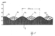
- Fig. 1 shows schematically a cross section through a layer 1 of polyurethane foam, the represents a porous absorber and an average layer thickness of, for example 15 mm has.
- the distance of the elevations 1a may be, for example, about 50 mm and the height difference to a recess 1b about 10 to 12 mm. This surface structure results compared to a foam layer of 15 mm thickness with a flat surface about a doubling the sound swallow area.
- This surface layer 1 c denotes a surface layer of the foam layer, which is melted and burning about 2 to 3 mm of the foam material formed on the surface For example, apply a hot roller under pressure over the foam layer is rolled off. This results in a largely closed surface of the combustion residues of the foam material, in particular polyurethane, but microporous is.
- This surface layer 1 c acts as a vibratory membrane and can be a Thickness in the range of 10 to 15 ⁇ have.
- This microporous surface layer or skin 1c is permeable to air, but not for Water or oil, because of the surface tension of liquids.
- imprints are preferably provided, which are the surface for the incident sound magnify and amplify diffraction effects of the sound.
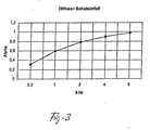
- Fig. 3 shows the absorption coefficient with diffuse sound incidence in dependence from the frequency.
- All incidence angles occur in diffuse sound fields on.
- the surface structure of Fig. 1 gives an optimal average angle of incidence. Due to the mostly oblique sound incidence on the surface occur almost wall-parallel components of the sound amplitude, where the longitudinal extent the foam layer comes into action, making these components look like a very thick foam layer can be effectively absorbed.
- sound absorption values achieved the on the only by the layer thickness computationally achievable sound absorption effect go clearly and otherwise only with multiple layer thicknesses of a conventional planar Foam material can be achieved.
- These high sound absorption values become supported by occurring diffraction effects on the indentations 1d, preferably in Diamond structure are provided on the surface.
- Fig. 2 shows the sound absorption of inventively designed foam layers at different average thickness dimensions depending on the Sound frequency. So it is at an average layer thickness of 30 mm and 630 Hz Absorption value ⁇ reached over 1.0, where 1.0 corresponds to 100%. For such an absorption value is in a foam layer of uniform thickness, ie without the inventive Wavy structure of the microporous surface, a layer thickness of 130 mm needed.
- FIGS. 4 and 5 The practical significance of such absorption values is illustrated by FIGS. 4 and 5.
- Fig. 4 shows the sound level decrease as a function of the sound absorption coefficient ⁇ .
- Fig. 5 reflects the subjective perceived volume reduction. After that, z. Legs Sound level reduction of 5 dB at a sound level of 60 dB already a volume reduction for the human ear of 29%.
- the back of the foam layer 1 may be coated with a reinforcing material be. It may also be self-adhesive to facilitate attachment to a wall.
- the distance of the flat elevations 1a can be varied, as well as the height between increase and depression. So the distance between the elevations 1a 40-60 mm, in particular 45-55 mm.
- the height between increase and recess can be 8 - 15 mm. In special cases, a distance Increases of up to 100 mm can be used.
- one is possible flat surface structuring provided the disadvantages of partially low volume density and thus to avoid worse absorption.
- the wavy surface structure is independent of the layer thickness of the used Foam.
- the wavy surface texture becomes designed so that at the lowest possible tread depth enlargement of the Surface of about 180 - 250% is achieved.
- FIG. 1 with a distance of the elevations of 50 mm and a difference between increase and depression from 10 to 12 mm results in about a doubling of the surface or an increase the surface of about 200%.
- the section line in Fig. 1 follows approximately a sinusoid. But it is also possible, for example, deepen the depressions and make the elevations wider than the depressions. It is essential that flat dome-shaped elevations 1a and also the recesses 1b rounded so flat are concave designed that results in a steady change in inclination of the surface.
- the described surface structure results in different types of foam material to a significant improvement of the sound absorption effect.
- polyurethane ester which is about 40% has open cell and about 60% closed-cell structure.
Landscapes
- Physics & Mathematics (AREA)
- Engineering & Computer Science (AREA)
- Acoustics & Sound (AREA)
- Multimedia (AREA)
- Soundproofing, Sound Blocking, And Sound Damping (AREA)
- Vehicle Interior And Exterior Ornaments, Soundproofing, And Insulation (AREA)
- Laminated Bodies (AREA)
- Building Environments (AREA)
Abstract
Description
- Fig. 1
- eine Schnittansicht durch eine Schaumstoffschicht,
- Fig. 2
- ein Diagramm, das den Schallabsorptionsgrad in Abhängigkeit von der Schallfrequenz wiedergibt,
- Fig. 3
- ein Diagramm, das den Absorptionskoeffizienten in Abhängigkeit von der Frequenz bei einer Schaumstoffschicht wiedergibt,
- Fig. 4
- ein Diagramm, das die Pegelabnahme als Funktion des Schallabsorptionsgrads wiedergibt, und
- Fig. 5
- eine Tabelle, die die subjektiv empfundene Lautstärkenreduzierung wiedergibt.
Claims (5)
- Schallabsorbierendes, schichtförmiges Schaumstoffmaterial, dessen dem Schalleinfall zugewandte Oberfläche mit Erhöhungen (1a) und Vertiefungen (1b) derart versehen ist, dass im Verhältnis zu einer Schaumstoffschicht von einheitlicher Dicke und gleichem Volumen pro Flächeneinheit die Oberfläche für den einfallenden Schall etwa auf zumindest das Doppelte vergrößert ist, wobei das Schaumstoffmaterial eine mikroporöse Oberflächenschicht (1c) aufweist.
- Schaumstoffmaterial nach Anspruch 1, wobei die Oberfläche um etwa 180 - 250 % gegenüber einer ebenen Oberfläche durch flache Erhöhungen vergrößert ist.
- Schaumstoffmaterial nach Anspruch 1 oder 2, wobei im Querschnitt der Schaumstoffschicht (1) die Oberfläche eine wellenförmige Struktur hat und in den Tälern der Schnittlinie versetzt dazu Erhöhungen einer benachbarten Schnittlinie angeordnet sind.
- Schaumstoffmaterial nach Anspruch 3, wobei die Erhöhungen (1a) einen Abstand von etwa 40 - 60 mm von einander haben und die Höhe zwischen Erhöhung und Vertiefung etwa 8 - 15 mm beträgt.
- Schaumstoffmaterial nach einem der vorhergehenden Ansprüche, wobei die Oberfläche mit Einprägungen, wie rautenförmig angeordneten Nutabschnitten (1d) oder kleineren Vertiefungen versehen ist.
Priority Applications (1)
| Application Number | Priority Date | Filing Date | Title |
|---|---|---|---|
| PL04029672T PL1544846T3 (pl) | 2003-12-15 | 2004-12-15 | Pochłaniający dźwięk płaski materiał z tworzywa piankowego |
Applications Claiming Priority (2)
| Application Number | Priority Date | Filing Date | Title |
|---|---|---|---|
| DE10358595A DE10358595A1 (de) | 2003-12-15 | 2003-12-15 | Schallabsorbierendes flächiges Schaumstoffmaterial |
| DE10358595 | 2003-12-15 |
Publications (3)
| Publication Number | Publication Date |
|---|---|
| EP1544846A2 true EP1544846A2 (de) | 2005-06-22 |
| EP1544846A3 EP1544846A3 (de) | 2012-11-28 |
| EP1544846B1 EP1544846B1 (de) | 2015-04-22 |
Family
ID=34485379
Family Applications (1)
| Application Number | Title | Priority Date | Filing Date |
|---|---|---|---|
| EP20040029672 Expired - Lifetime EP1544846B1 (de) | 2003-12-15 | 2004-12-15 | Schallabsorbierendes flächiges Schaumstoffmaterial |
Country Status (7)
| Country | Link |
|---|---|
| EP (1) | EP1544846B1 (de) |
| DE (1) | DE10358595A1 (de) |
| DK (1) | DK1544846T3 (de) |
| ES (1) | ES2543083T3 (de) |
| HU (1) | HUE025109T2 (de) |
| PL (1) | PL1544846T3 (de) |
| PT (1) | PT1544846E (de) |
Cited By (1)
| Publication number | Priority date | Publication date | Assignee | Title |
|---|---|---|---|---|
| CN108231053A (zh) * | 2018-03-13 | 2018-06-29 | 吉林大学 | 一种具有凸包形态的声学包装材料及其制备方法 |
Family Cites Families (4)
| Publication number | Priority date | Publication date | Assignee | Title |
|---|---|---|---|---|
| DE2246621A1 (de) * | 1972-09-22 | 1974-03-28 | Albert Schrey | Akustikplatte |
| DE2915823A1 (de) * | 1979-04-19 | 1980-11-06 | Irbit Holding Ag | Schall-daemmplatte |
| DE3219339C1 (de) * | 1982-05-22 | 1983-02-03 | Metzeler Schaum Gmbh, 8940 Memmingen | Flaechiges Element zur Luftschall-Absorption |
| DE3313001A1 (de) * | 1983-04-12 | 1984-10-18 | Volkswagenwerk Ag, 3180 Wolfsburg | Schallabsorbierende schicht |
-
2003
- 2003-12-15 DE DE10358595A patent/DE10358595A1/de not_active Withdrawn
-
2004
- 2004-12-15 PL PL04029672T patent/PL1544846T3/pl unknown
- 2004-12-15 EP EP20040029672 patent/EP1544846B1/de not_active Expired - Lifetime
- 2004-12-15 ES ES04029672.5T patent/ES2543083T3/es not_active Expired - Lifetime
- 2004-12-15 PT PT40296725T patent/PT1544846E/pt unknown
- 2004-12-15 DK DK04029672.5T patent/DK1544846T3/en active
- 2004-12-15 HU HUE04029672A patent/HUE025109T2/en unknown
Cited By (1)
| Publication number | Priority date | Publication date | Assignee | Title |
|---|---|---|---|---|
| CN108231053A (zh) * | 2018-03-13 | 2018-06-29 | 吉林大学 | 一种具有凸包形态的声学包装材料及其制备方法 |
Also Published As
| Publication number | Publication date |
|---|---|
| HUE025109T2 (en) | 2016-01-28 |
| EP1544846B1 (de) | 2015-04-22 |
| EP1544846A3 (de) | 2012-11-28 |
| DK1544846T3 (en) | 2015-07-27 |
| PT1544846E (pt) | 2015-09-14 |
| PL1544846T3 (pl) | 2015-10-30 |
| DE10358595A1 (de) | 2005-07-21 |
| ES2543083T3 (es) | 2015-08-14 |
Similar Documents
| Publication | Publication Date | Title |
|---|---|---|
| DE10347084B4 (de) | Abstimmbare, den Schall absorbierende, und die Luft filternde Dämpfungseinrichtung und Herstellungsverfahren | |
| DE3233654C2 (de) | Schallabsorbierendes Bauelement | |
| DE2921050C2 (de) | ||
| DE2408028C3 (de) | ||
| EP2937483B1 (de) | Bauplatte, insbesondere wand- oder deckenplatte | |
| DE8700264U1 (de) | Aus Schaumstoff bestehende Schalldämmplatte | |
| EP2655744B1 (de) | Schallschutzbauteil | |
| EP0742322B1 (de) | Schalldämpfungsvorrichtung | |
| EP2993037B1 (de) | Gefüllte metallsandwichstruktur | |
| EP1544846B1 (de) | Schallabsorbierendes flächiges Schaumstoffmaterial | |
| EP3246479B1 (de) | Absorbereinheit zum absorbieren von schall | |
| EP3310965B1 (de) | Schallabsorbierendes bauelement und schallschutzwand mit einem solchen bauelement | |
| DE102015109808A1 (de) | Schallabsorbierendes Bauelement und Schallschutzwand mit einem solchen | |
| DE3506488A1 (de) | Geraeuschdaemmender schichtkoerper | |
| DE2502846C3 (de) | Absorber zur Dämpfung von Schall- und elektromagnetischen Wellen | |
| EP3555370B1 (de) | Schallabsorbierendes bauelement mit löschungsprofilen sowie schallschutzwand | |
| DE19616340C2 (de) | Schallschutzelement sowie ein Verfahren zu dessen Herstellung | |
| DE1303368B (de) | ||
| EP1544847A2 (de) | Schallabsorbierendes flächiges Schaumstoffmaterial | |
| DE10327633B4 (de) | Vorrichtung zur Absorption von Schallenergie aus Schallwellen in flüssigen oder in gasförmigen Medien | |
| DE10052070A1 (de) | Mobile Trennwand | |
| DE2655587C3 (de) | Lärmschutzwand | |
| AT509717B1 (de) | Lärmschutzelement | |
| EP1612331A1 (de) | Steinkorb zur Erstellung einer Schallschutzwand | |
| DE202006017814U1 (de) | Schallabsorbierendes Hitzeschild |
Legal Events
| Date | Code | Title | Description |
|---|---|---|---|
| PUAI | Public reference made under article 153(3) epc to a published international application that has entered the european phase |
Free format text: ORIGINAL CODE: 0009012 |
|
| AK | Designated contracting states |
Kind code of ref document: A2 Designated state(s): AT BE BG CH CY CZ DE DK EE ES FI FR GB GR HU IE IS IT LI LT LU MC NL PL PT RO SE SI SK TR |
|
| AX | Request for extension of the european patent |
Extension state: AL BA HR LV MK YU |
|
| PUAL | Search report despatched |
Free format text: ORIGINAL CODE: 0009013 |
|
| AK | Designated contracting states |
Kind code of ref document: A3 Designated state(s): AT BE BG CH CY CZ DE DK EE ES FI FR GB GR HU IE IS IT LI LT LU MC NL PL PT RO SE SI SK TR |
|
| AX | Request for extension of the european patent |
Extension state: AL BA HR LV MK YU |
|
| RIC1 | Information provided on ipc code assigned before grant |
Ipc: G10K 11/16 20060101AFI20121024BHEP |
|
| 17P | Request for examination filed |
Effective date: 20130404 |
|
| AKX | Designation fees paid |
Designated state(s): AT BE BG CH CY CZ DE DK EE ES FI FR GB GR HU IE IS IT LI LT LU MC NL PL PT RO SE SI SK TR |
|
| GRAP | Despatch of communication of intention to grant a patent |
Free format text: ORIGINAL CODE: EPIDOSNIGR1 |
|
| INTG | Intention to grant announced |
Effective date: 20141113 |
|
| GRAS | Grant fee paid |
Free format text: ORIGINAL CODE: EPIDOSNIGR3 |
|
| GRAA | (expected) grant |
Free format text: ORIGINAL CODE: 0009210 |
|
| AK | Designated contracting states |
Kind code of ref document: B1 Designated state(s): AT BE BG CH CY CZ DE DK EE ES FI FR GB GR HU IE IS IT LI LT LU MC NL PL PT RO SE SI SK TR |
|
| REG | Reference to a national code |
Ref country code: GB Ref legal event code: FG4D Free format text: NOT ENGLISH |
|
| REG | Reference to a national code |
Ref country code: CH Ref legal event code: EP |
|
| REG | Reference to a national code |
Ref country code: AT Ref legal event code: REF Ref document number: 723651 Country of ref document: AT Kind code of ref document: T Effective date: 20150515 |
|
| REG | Reference to a national code |
Ref country code: IE Ref legal event code: FG4D Free format text: LANGUAGE OF EP DOCUMENT: GERMAN |
|
| REG | Reference to a national code |
Ref country code: DE Ref legal event code: R096 Ref document number: 502004014889 Country of ref document: DE Effective date: 20150603 |
|
| REG | Reference to a national code |
Ref country code: DK Ref legal event code: T3 Effective date: 20150723 |
|
| REG | Reference to a national code |
Ref country code: SE Ref legal event code: TRGR |
|
| REG | Reference to a national code |
Ref country code: NL Ref legal event code: T3 |
|
| REG | Reference to a national code |
Ref country code: ES Ref legal event code: FG2A Ref document number: 2543083 Country of ref document: ES Kind code of ref document: T3 Effective date: 20150814 |
|
| REG | Reference to a national code |
Ref country code: PT Ref legal event code: SC4A Free format text: AVAILABILITY OF NATIONAL TRANSLATION Effective date: 20150721 |
|
| REG | Reference to a national code |
Ref country code: LT Ref legal event code: MG4D |
|
| PG25 | Lapsed in a contracting state [announced via postgrant information from national office to epo] |
Ref country code: FI Free format text: LAPSE BECAUSE OF FAILURE TO SUBMIT A TRANSLATION OF THE DESCRIPTION OR TO PAY THE FEE WITHIN THE PRESCRIBED TIME-LIMIT Effective date: 20150422 Ref country code: LT Free format text: LAPSE BECAUSE OF FAILURE TO SUBMIT A TRANSLATION OF THE DESCRIPTION OR TO PAY THE FEE WITHIN THE PRESCRIBED TIME-LIMIT Effective date: 20150422 |
|
| REG | Reference to a national code |
Ref country code: PL Ref legal event code: T3 |
|
| PG25 | Lapsed in a contracting state [announced via postgrant information from national office to epo] |
Ref country code: GR Free format text: LAPSE BECAUSE OF FAILURE TO SUBMIT A TRANSLATION OF THE DESCRIPTION OR TO PAY THE FEE WITHIN THE PRESCRIBED TIME-LIMIT Effective date: 20150723 Ref country code: IS Free format text: LAPSE BECAUSE OF FAILURE TO SUBMIT A TRANSLATION OF THE DESCRIPTION OR TO PAY THE FEE WITHIN THE PRESCRIBED TIME-LIMIT Effective date: 20150822 |
|
| REG | Reference to a national code |
Ref country code: DE Ref legal event code: R097 Ref document number: 502004014889 Country of ref document: DE |
|
| REG | Reference to a national code |
Ref country code: HU Ref legal event code: AG4A Ref document number: E025109 Country of ref document: HU |
|
| PG25 | Lapsed in a contracting state [announced via postgrant information from national office to epo] |
Ref country code: EE Free format text: LAPSE BECAUSE OF FAILURE TO SUBMIT A TRANSLATION OF THE DESCRIPTION OR TO PAY THE FEE WITHIN THE PRESCRIBED TIME-LIMIT Effective date: 20150422 |
|
| PLBE | No opposition filed within time limit |
Free format text: ORIGINAL CODE: 0009261 |
|
| STAA | Information on the status of an ep patent application or granted ep patent |
Free format text: STATUS: NO OPPOSITION FILED WITHIN TIME LIMIT |
|
| PG25 | Lapsed in a contracting state [announced via postgrant information from national office to epo] |
Ref country code: RO Free format text: LAPSE BECAUSE OF NON-PAYMENT OF DUE FEES Effective date: 20150422 Ref country code: SK Free format text: LAPSE BECAUSE OF FAILURE TO SUBMIT A TRANSLATION OF THE DESCRIPTION OR TO PAY THE FEE WITHIN THE PRESCRIBED TIME-LIMIT Effective date: 20150422 |
|
| 26N | No opposition filed |
Effective date: 20160125 |
|
| PG25 | Lapsed in a contracting state [announced via postgrant information from national office to epo] |
Ref country code: SI Free format text: LAPSE BECAUSE OF FAILURE TO SUBMIT A TRANSLATION OF THE DESCRIPTION OR TO PAY THE FEE WITHIN THE PRESCRIBED TIME-LIMIT Effective date: 20150422 Ref country code: BE Free format text: LAPSE BECAUSE OF NON-PAYMENT OF DUE FEES Effective date: 20151231 |
|
| REG | Reference to a national code |
Ref country code: DK Ref legal event code: EBP Effective date: 20151231 |
|
| PG25 | Lapsed in a contracting state [announced via postgrant information from national office to epo] |
Ref country code: MC Free format text: LAPSE BECAUSE OF FAILURE TO SUBMIT A TRANSLATION OF THE DESCRIPTION OR TO PAY THE FEE WITHIN THE PRESCRIBED TIME-LIMIT Effective date: 20150422 Ref country code: LU Free format text: LAPSE BECAUSE OF FAILURE TO SUBMIT A TRANSLATION OF THE DESCRIPTION OR TO PAY THE FEE WITHIN THE PRESCRIBED TIME-LIMIT Effective date: 20151215 Ref country code: CZ Free format text: LAPSE BECAUSE OF NON-PAYMENT OF DUE FEES Effective date: 20151215 |
|
| REG | Reference to a national code |
Ref country code: CH Ref legal event code: PL |
|
| REG | Reference to a national code |
Ref country code: SE Ref legal event code: EUG |
|
| GBPC | Gb: european patent ceased through non-payment of renewal fee |
Effective date: 20151215 |
|
| PG25 | Lapsed in a contracting state [announced via postgrant information from national office to epo] |
Ref country code: SE Free format text: LAPSE BECAUSE OF NON-PAYMENT OF DUE FEES Effective date: 20151216 |
|
| REG | Reference to a national code |
Ref country code: NL Ref legal event code: MM Effective date: 20160101 |
|
| REG | Reference to a national code |
Ref country code: IE Ref legal event code: MM4A |
|
| REG | Reference to a national code |
Ref country code: FR Ref legal event code: ST Effective date: 20160831 |
|
| PG25 | Lapsed in a contracting state [announced via postgrant information from national office to epo] |
Ref country code: LI Free format text: LAPSE BECAUSE OF NON-PAYMENT OF DUE FEES Effective date: 20151231 Ref country code: GB Free format text: LAPSE BECAUSE OF NON-PAYMENT OF DUE FEES Effective date: 20151215 Ref country code: IE Free format text: LAPSE BECAUSE OF NON-PAYMENT OF DUE FEES Effective date: 20151215 Ref country code: NL Free format text: LAPSE BECAUSE OF NON-PAYMENT OF DUE FEES Effective date: 20160101 Ref country code: CH Free format text: LAPSE BECAUSE OF NON-PAYMENT OF DUE FEES Effective date: 20151231 Ref country code: HU Free format text: LAPSE BECAUSE OF NON-PAYMENT OF DUE FEES Effective date: 20151216 |
|
| PG25 | Lapsed in a contracting state [announced via postgrant information from national office to epo] |
Ref country code: FR Free format text: LAPSE BECAUSE OF NON-PAYMENT OF DUE FEES Effective date: 20151231 Ref country code: PT Free format text: LAPSE BECAUSE OF NON-PAYMENT OF DUE FEES Effective date: 20160915 |
|
| REG | Reference to a national code |
Ref country code: ES Ref legal event code: FD2A Effective date: 20170127 |
|
| PG25 | Lapsed in a contracting state [announced via postgrant information from national office to epo] |
Ref country code: DK Free format text: LAPSE BECAUSE OF NON-PAYMENT OF DUE FEES Effective date: 20151231 |
|
| REG | Reference to a national code |
Ref country code: AT Ref legal event code: MM01 Ref document number: 723651 Country of ref document: AT Kind code of ref document: T Effective date: 20151215 |
|
| PG25 | Lapsed in a contracting state [announced via postgrant information from national office to epo] |
Ref country code: PL Free format text: LAPSE BECAUSE OF NON-PAYMENT OF DUE FEES Effective date: 20151215 Ref country code: IT Free format text: LAPSE BECAUSE OF NON-PAYMENT OF DUE FEES Effective date: 20151215 Ref country code: ES Free format text: LAPSE BECAUSE OF NON-PAYMENT OF DUE FEES Effective date: 20151216 |
|
| PG25 | Lapsed in a contracting state [announced via postgrant information from national office to epo] |
Ref country code: AT Free format text: LAPSE BECAUSE OF NON-PAYMENT OF DUE FEES Effective date: 20151215 Ref country code: BG Free format text: LAPSE BECAUSE OF FAILURE TO SUBMIT A TRANSLATION OF THE DESCRIPTION OR TO PAY THE FEE WITHIN THE PRESCRIBED TIME-LIMIT Effective date: 20150422 |
|
| PG25 | Lapsed in a contracting state [announced via postgrant information from national office to epo] |
Ref country code: CY Free format text: LAPSE BECAUSE OF FAILURE TO SUBMIT A TRANSLATION OF THE DESCRIPTION OR TO PAY THE FEE WITHIN THE PRESCRIBED TIME-LIMIT Effective date: 20150422 |
|
| P01 | Opt-out of the competence of the unified patent court (upc) registered |
Effective date: 20230607 |
|
| PGFP | Annual fee paid to national office [announced via postgrant information from national office to epo] |
Ref country code: DE Payment date: 20231208 Year of fee payment: 20 |
|
| PG25 | Lapsed in a contracting state [announced via postgrant information from national office to epo] |
Ref country code: TR Free format text: LAPSE BECAUSE OF NON-PAYMENT OF DUE FEES Effective date: 20151215 |
|
| REG | Reference to a national code |
Ref country code: DE Ref legal event code: R071 Ref document number: 502004014889 Country of ref document: DE |