EP1544911B1 - Justiervorrichtung - Google Patents
Justiervorrichtung Download PDFInfo
- Publication number
- EP1544911B1 EP1544911B1 EP04028528A EP04028528A EP1544911B1 EP 1544911 B1 EP1544911 B1 EP 1544911B1 EP 04028528 A EP04028528 A EP 04028528A EP 04028528 A EP04028528 A EP 04028528A EP 1544911 B1 EP1544911 B1 EP 1544911B1
- Authority
- EP
- European Patent Office
- Prior art keywords
- receptacle
- adjusting device
- cables
- ropes
- recording
- Prior art date
- Legal status (The legal status is an assumption and is not a legal conclusion. Google has not performed a legal analysis and makes no representation as to the accuracy of the status listed.)
- Expired - Lifetime
Links
Images

Classifications
-
- G—PHYSICS
- G03—PHOTOGRAPHY; CINEMATOGRAPHY; ANALOGOUS TECHNIQUES USING WAVES OTHER THAN OPTICAL WAVES; ELECTROGRAPHY; HOLOGRAPHY
- G03F—PHOTOMECHANICAL PRODUCTION OF TEXTURED OR PATTERNED SURFACES, e.g. FOR PRINTING, FOR PROCESSING OF SEMICONDUCTOR DEVICES; MATERIALS THEREFOR; ORIGINALS THEREFOR; APPARATUS SPECIALLY ADAPTED THEREFOR
- G03F7/00—Photomechanical, e.g. photolithographic, production of textured or patterned surfaces, e.g. printing surfaces; Materials therefor, e.g. comprising photoresists; Apparatus specially adapted therefor
- G03F7/70—Microphotolithographic exposure; Apparatus therefor
- G03F7/70691—Handling of masks or workpieces
- G03F7/70758—Drive means, e.g. actuators, motors for long- or short-stroke modules or fine or coarse driving
-
- G—PHYSICS
- G03—PHOTOGRAPHY; CINEMATOGRAPHY; ANALOGOUS TECHNIQUES USING WAVES OTHER THAN OPTICAL WAVES; ELECTROGRAPHY; HOLOGRAPHY
- G03F—PHOTOMECHANICAL PRODUCTION OF TEXTURED OR PATTERNED SURFACES, e.g. FOR PRINTING, FOR PROCESSING OF SEMICONDUCTOR DEVICES; MATERIALS THEREFOR; ORIGINALS THEREFOR; APPARATUS SPECIALLY ADAPTED THEREFOR
- G03F7/00—Photomechanical, e.g. photolithographic, production of textured or patterned surfaces, e.g. printing surfaces; Materials therefor, e.g. comprising photoresists; Apparatus specially adapted therefor
- G03F7/70—Microphotolithographic exposure; Apparatus therefor
- G03F7/70691—Handling of masks or workpieces
- G03F7/70716—Stages
-
- H—ELECTRICITY
- H10—SEMICONDUCTOR DEVICES; ELECTRIC SOLID-STATE DEVICES NOT OTHERWISE PROVIDED FOR
- H10P—GENERIC PROCESSES OR APPARATUS FOR THE MANUFACTURE OR TREATMENT OF DEVICES COVERED BY CLASS H10
- H10P72/00—Handling or holding of wafers, substrates or devices during manufacture or treatment thereof
- H10P72/50—Handling or holding of wafers, substrates or devices during manufacture or treatment thereof for positioning, orientation or alignment
- H10P72/57—Mask-wafer alignment
Definitions
- the invention relates to an adjusting device for aligning an object in a plane.
- the EP 04 699 56 A discloses an adjusting device in which ropes are arranged at different heights via a table at the receiving part. It would not be obvious from that EP 04 699 56 A Knocking known ropes on joints on the recording because this, without further changes to the recording, would lead to impaired freedom of movement of the ropes.
- the EP 04 377 41 A discloses an adjusting device with rigid traction elements.
- the US 5,040,431 A shows an adjusting device with a device for fixed positioning of a recording on a table.
- An adjustment of a receiving part is shown by implementing translational movements via elastic hinges. It would not be obvious from that JP 61 2700 44 A
- the DE 101 28 713 A1 describes an adjustment table of the aforementioned type with an outer frame, an intermediate frame, which is movable in a first direction relative to the outer frame, and a receiving part for the object to be adjusted, said receiving part is in turn arranged slidably in a further direction within the intermediate frame.
- Mechanical adjustment allow the displaceability of said parts to each other and their subsequent fixation in a desired position.
- the adjustment paths are very limited.
- a secondary aspect is to ensure an exact adjustability even if, for example, pressure is exerted on the object to be adjusted in further method steps. This is the case, for example, when the article (for example a wafer, thermally deformable plastic or a film) is embossed.
- the invention is based on the finding that it is not absolutely necessary for a precise and extremely precise adjustment (with tolerances in the ⁇ m range and below) to provide a more or less “rigid” adjustment system.
- the desired goal can also be achieved in the manner of a "floating" adjustment, provided that in particular the following requirements are met:
- the adjustment unit must be exactly definable after reaching the desired adjustment position.
- the basic idea of the invention is to releasably fix the object to be adjusted in or on a receptacle, wherein this receptacle can be brought along an associated table into the desired position, by means of cables. Regardless of the size and shape of the recording, at least three cables are necessary in order to realize the desired x, y and angular displacement.
- the respective object can be aligned exactly with respect to all the degrees of freedom mentioned.
- the invention in its most general embodiment relates to an adjusting device according to claim 1.
- the recording is substantially parallel to the table surface in any direction displaced.
- the table can be aligned horizontally.
- the table can also run obliquely to the horizontal, up to a vertical position.
- the final position of the receptacle, relative to the table, is adjusted via said ropes and can then be additionally fixed, as will be explained.
- the object to be adjusted is releasably fixed in the receptacle. This can be done for example mechanically by clamping, latching or the like. Another possibility is to suck the object on or in the receptacle by negative pressure. As far as the ropes are hinged to the recording, this means that when pulling a rope tensile force on the recording takes place and thus a directional shift. Accordingly, at the same time other ropes are carried along or tracked to allow the desired displacement of the recording (and in parallel the object).
- the cables must act in the opposite direction in order, for example, to take the image to the right or to move left.
- the feature according to which the cables are intended to act in at least two different directions does not necessarily mean opposite directions. Rather, this results in the basic orientation of the ropes.
- Two ropes can be attached to different sections of the Attacking record, and for example, are angularly offset from each other, not only a shift to the right or left (or: top and bottom) effect, but at the same time lead to an angular displacement of the recording relative to the table. This will be explained in more detail below.
- an embodiment of the invention provides that the cables are arranged articulated on the receptacle, but stationary.
- the articulation point is fixed.
- the orientation of the cable relative to the receptacle (for example, the angle between the cable and the corresponding edge of the receptacle) may change.
- a device for winding and unwinding of the rope is arranged at a distance from the articulation point.
- the ropes can be guided between their ends via pulleys. You can also be passed through the table under the table, where, for example, motors are arranged over which the ropes are activated.
- the first ends of the cables are articulated on opposite sections of the receptacle.
- two ropes along one side edge for example at the end, and a third rope in the middle of the opposite edge can be arranged.
- the articulation areas of the cables are, for example, in the peripheral region of the receptacle.
- the first ends of the cables corresponding to a maximum distance from each other.
- the articulation points can form the corners of an imaginary triangle.
- the imaginary connecting lines between the articulation areas can describe a rectangle, for example a square, but also a trapezoid.
- rope includes wires, tapes and threads.
- the position of the image can be determined directly.
- an independent measuring device which serves for the direct determination of the position of the recording on the table.
- This is for example an optical measuring unit, such as a camera, a microscope or the like.
- a measuring device for determining the position or length of each first end of the cables is provided in each case.
- an evaluation unit calculates the position of the recording on the table from the corresponding coordinates.
- Such measuring devices may comprise transmitter / receiver, wherein each one transmitter / receiver unit may be associated with a rope.
- the recording is preferably fixed fixed (positioned). This is important, for example, when the object to be adjusted is subsequently subjected to pressure, for example by embossing. It is then ensured that even during the embossing process, the position of the recording and thus the object is not changed.
- the device may for example be a device for firmly sucking the recording on the table.
- a corresponding suction unit can also be used for (temporarily) fixing the object on or in the receptacle. To change the object, the vacuum is simply interrupted.
- recording and table lubricant In order to allow a frictionless and thus trouble-free mobility of the recording on the table can be provided between recording and table lubricant. These may be liquid or viscous lubricants. Likewise, however, mechanical lubricants, such as ball rollers etc. or the formation of an air bearing are possible.
- air bearing includes, for example, embodiments that make use of the "Bernoulli effect" in which an air cushion between the table and recording is formed.
- the aforementioned air cushion (air bearing) can be interrupted and the recording be sucked onto the table when the final adjustment position is reached.
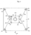
- the device comprises a table 10, which here has a square base with corresponding four corner regions 10a-d. In the corner regions 10a-d, in each case a bore 12 runs through the table. Approximately in the center is a receptacle 14 on the table, which has a cuboid shape with a square plan and whose four corners are marked 14a-d.
- a wafer 16 In a recess of the receptacle 14 is a wafer 16 to be positioned.
- hinges 18a-d which are pivotable along a plane parallel to the table 10, are arranged on opposite edges 14e, f of the receptacle 14.
- a rope 20a extends in the direction of the corner 10c of the table 10, where the rope 20a is guided around a deflection roller 22a through the associated opening 12 under the table 10, where it is around a further deflection roller 24a is guided to a drive unit 26a, in which the rope 22a can be motor-up or unwound.
- a line 28a extends to a computer 30th
- a cable 20b extends from an articulated arm 18bb in the direction of the corner 10d and runs via deflecting rollers 22b, 24b to a drive unit 26b, from which in turn a line 28b extends to the computer 30.
- the ropes 20a-d are stretched.
- the ropes 20a, 20b extend in a different direction (substantially opposite) to the ropes 20c, 20d.
- the course of the cables 20a, 20b is substantially mirror-inverted to the course of the cables 20c, 20d.
- the system is stable in itself.
- the position of the receptacle 14 relative to the table 10, however, can be adjusted, and thus position the wafer 16 in a desired manner, when now the drive units (such as 26a, 26b) are activated and thereby the corresponding cables 20a-d shortened or be extended (tracked).
- the drive units such as 26a, 26b
- the receptacle 14 can be moved both in the x and y directions.
- there is an angular displacement which is represented by the arrow ⁇ .
- the ropes 20a, 20d are tracked via the computer 30 and the associated drive units.
- a distance measuring system is provided which operates on a laser basis.
- a measuring system is associated with each cable 20a-d and is explained below by way of example for the cable 20a.
- a transmitter 32a is arranged, which transmits a laser beam to a receiver 34a, which is arranged above the articulated arm 18aa.
- the transmitter 32a is stationary, but pivotable (rotatable).
- the receiver 34a changes its position in accordance with the adjustment of the receptacle 14.
- the measuring device is also connected to the computer 30 via a line 36a.
- the exact alignment of the receptacle 14 and thus of the wafer 16 can be calculated in this way, continuously, during the adjustment and in the final final position ,
- an optical measuring device which indicates the exact position of the receptacle 14 on the table 10, could be arranged above the receptacle 14.
- the table 10 may be provided below the receptacle 14 with a plurality of capillary bores, which are connectable to a vacuum source in order to suck the receptacle 14 after reaching the desired end position stationary against the table can.
- an air cushion can be formed between the receptacle 14 and the table 10, for example in the manner of the so-called “Bernoulli effect", wherein the same capillaries can be used.
Landscapes
- Physics & Mathematics (AREA)
- General Physics & Mathematics (AREA)
- Container, Conveyance, Adherence, Positioning, Of Wafer (AREA)
- Exposure And Positioning Against Photoresist Photosensitive Materials (AREA)
- Registering Or Overturning Sheets (AREA)
- Valve Device For Special Equipments (AREA)
- Details Of Measuring And Other Instruments (AREA)
- Particle Accelerators (AREA)
- Vibration Prevention Devices (AREA)
- Manufacture, Treatment Of Glass Fibers (AREA)
Description
- Die Erfindung betrifft eine Justiervorrichtung zur Ausrichtung eines Gegenstandes in einer Ebene.
- Beispielsweise bei der Erstellung von elektrischen Strukturen (Schaltungen) auf Halbleiterscheiben (Wafern) mittels lithographischer Verfahren ist es notwendig, den Wafer gegenüber einer Maske in einer horizontalen Ebene exakt zu positionieren. Eine entsprechende Problematik ergibt sich auch im Bereich weiterer verfahrenstechnischer Stufen bei der Herstellung, Bearbeitung oder Verarbeitung von Wafern.
- Der Stand der Technik und die Erfindung werden nachstehend anhand der Justierung eines Wafers auf/in einer Aufnahme näher beschrieben. Die Erfindung ist insoweit jedoch nicht auf diesen Anwendungsbereich beschränkt, sondern dient der Ausrichtung beliebiger Gegenstände.
- Während die Ausrichtung des Wafers in x- und y-Richtung innerhalb einer Ebene beispielsweise mit einem Mikroskop überwacht werden kann, bereitet es erhebliche konstruktive Probleme, den Wafer auf einem entsprechenden Aufnahmeteil zu konfektionieren, der die gewünschte Beweglichkeit in x- und y-Richtung sowie eine sichere Fixierung der jeweiligen Endposition gewährleistet.
- Die
EP 04 699 56 A offenbart eine Justiervorrichtung, bei der Seile in unterschiedlichen Höhen über einen Tisch an deren Aufnahmeteil angeordnet sind. Es wäre nicht naheliegend die ausEP 04 699 56 A bekannten Seile über Gelenke an der Aufnahme anzulenken da dies, ohne weiteren Änderungen der Aufnahme, zu Beeinträchtigungen der Bewegungsfreiheit der Seile führen würde. DieEP 04 377 41 A offenbart dagegen eine Justiervorrichtung mit starren Zugorganen. DieUS 5,040,431 A zeigt eine Justiervorrichtung mit einer Einrichtung zur ortsfesten Positionierung einer Aufnahme auf einem Tisch. In derJP 61 27 00 44 A JP 61 2700 44 A - Die
DE 101 28 713 A1 beschreibt einen Justiertisch der vorgenannten Art mit einem äußeren Rahmen, einem Zwischenrahmen, welcher in einer ersten Richtung relativ zum äußeren Rahmen bewegbar ist, und einem Aufnahmeteil für den zu justierenden Gegenstand, wobei dieser Aufnahmeteil wiederum in einer weiteren Richtung innerhalb des Zwischenrahmens verschiebbar angeordnet wird. Mechanische Verstelleinrichtungen ermöglichen die Verschiebbarkeit der genannten Teile zueinander und deren anschließende Fixierung in einer gewünschten Position. Die Verstellwege sind stark limitiert. - Dieser Justiertisch hat sich grundsätzlich bewährt. Mit der Erfindung soll eine alternative konstruktive Gestaltung vorgestellt werden. Ein Nebenaspekt ist, eine exakte Justierbarkeit auch dann zu gewährleisten, wenn bei weiteren Verfahrensschritten beispielsweise Druck auf den zu justierenden Gegenstand ausgeübt wird. Dies ist zum Beispiel dann der Fall, wenn der Gegenstand (zum Beispiel ein Wafer, thermisch verformbarer Kunststoff oder eine Folie) geprägt wird.
- Der Erfindung liegt die Erkenntnis zugrunde, dass es auch für eine exakte und äußerst präzise Justierung (mit Toleranzen im µm-Bereich und darunter) nicht unbedingt notwendig ist, ein mehr oder weniger "starres" Justiersystem bereitzustellen. Das gewünschte Ziel lässt sich auch nach Art einer "schwimmenden" Justierung erreichen, sofern insbesondere folgende Anforderungen erfüllt werden:
- Es müssen sich sehr kleine Verschiebewege beispielsweise in x- und y-Richtung sowie entsprechende Winkelverschiebungen realisieren lassen.
- Die Justiereinheit muss nach Erreichen der gewünschten Justierposition exakt definierbar sein.
- Grundgedanke der Erfindung ist es, den zu justierenden Gegenstand in oder auf einer Aufnahme lösbar zu fixieren, wobei diese Aufnahme entlang eines zugehörigen Tisches in die gewünschte Position gebracht werden kann, und zwar mittels Seilen. Unabhängig von der Größe und Form der Aufnahme sind dabei mindestens drei Seile notwendig, um die gewünschte x-, y- und Winkelverschiebung realisieren zu können.
- Werden die drei Seile beispielsweise an den Ecken eines gedachten, beispielsweise gleichwinkligen Dreiecks angeordnet, oder bei vier Seilen im Bereich der Ecken eines Rechteckes (insbesondere eines Quadrates) oder eines Trapezes, so lässt sich der jeweilige Gegenstand bezüglich aller genannten Freiheitsgrade exakt ausrichten.
- Danach betrifft die Erfindung in ihrer allgemeinsten Ausführungsform eine Justiervorrichtung gemäß Patentanspruch 1.
- Soweit die Aufnahme auf dem Tisch positionierbar sein soll bedeutet dies, dass die Aufnahme im Wesentlichen parallel zur Tischoberfläche in beliebigen Richtungen verschiebbar ist. Dabei kann der Tisch horizontal ausgerichtet sein. Der Tisch kann aber auch schräg zur Horizontalen verlaufen, bis hin zu einer vertikalen Position.
- Die endgültige Position der Aufnahme, relativ zum Tisch, wird über die genannten Seile eingestellt und kann dann zusätzlich fixiert werden, wie noch erläutert wird.
- Der zu justierende Gegenstand wird lösbar in der Aufnahme fixiert. Dies kann zum Beispiel mechanisch durch Klemmung, Verrastung oder dergleichen erfolgen. Eine andere Möglichkeit besteht darin, den Gegenstand an oder in der Aufnahme durch Unterdruck festzusaugen. Soweit die Seile an der Aufnahme angelenkt sind bedeutet dies, dass bei Zugbelastung eines Seils eine Zugkraft auf die Aufnahme erfolgt und damit eine Richtungsverschiebung. Entsprechend werden gleichzeitig andere Seile mitgeführt oder nachgeführt, um die gewünschte Verschiebung der Aufnahme (und parallel dazu des Gegenstandes) zu ermöglichen.
- Geht man davon aus, dass die Aufnahme auf einem horizontalen Tisch verschiebbar angeordnet ist so ergibt sich bereits dann, wenn man nur eine Verschieberichtung (beispielsweise x-Richtung) betrachtet, dass die Seile in entgegengesetzter Richtung wirken müssen, um die Aufnahme beispielsweise nach rechts oder links verschieben zu können. Das Merkmal, gemäß dem die Seile in mindestens zwei unterschiedlichen Richtungen wirken sollen, bedeutet dabei nicht zwangsläufig entgegengesetzte Richtungen. Vielmehr ergibt sich daraus die grundsätzliche Orientierung der Seile. Dabei können bereits zwei Seile, die an unterschiedlichen Abschnitten der Aufnahme angreifen, und beispielsweise winkelmäßig versetzt zueinander sind, nicht nur eine Verschiebung nach rechts oder links (oder: oben und unten) bewirken, sondern gleichzeitig auch zu einer Winkelverschiebung der Aufnahme relativ zum Tisch führen. Auch dies wird nachstehend näher erläutert.
- Insbesondere um die gewünschte Winkelverschiebung zu ermöglichen sieht eine Ausführungsform der Erfindung vor, dass die Seile an der Aufnahme gelenkig, aber ortsfest angeordnet sind. Der Anlenkpunkt ist dabei fixiert. Die Orientierung des Seils gegenüber der Aufnahme (beispielsweise der Winkel zwischen Seil und korrespondierender Kante der Aufnahme) kann sich jedoch verändern. Eine Einrichtung zum Auf- und Abwickeln des Seils wird im Abstand zur Anlenkstelle angeordnet.
- Die Seile können zwischen ihren Enden über Umlenkrollen geführt werden. Sie können dabei auch durch den Tisch hindurch unter den Tisch geführt werden, wo beispielsweise Motoren angeordnet sind, über die die Seile aktivierbar sind.
- Wie bereits ausgeführt sind die ersten Enden der Seile an gegenüberliegenden Abschnitten der Aufnahme angelenkt. Bei einer in der Aufsicht quadratischen Aufnahme können beispielsweise zwei Seile entlang einer Seitenkante, beispielsweise jeweils am Ende, und ein drittes Seil in der Mitte der gegenüberliegenden Kante angeordnet werden.
- Die Anlenkbereiche der Seile sind beispielsweise im Umfangsbereich der Aufnahme.
- Je größer der Abstand der Anlenkstellen der Seile zueinander ist um so größer sind die Verstellmöglichkeiten zur Positionierung der Aufnahme (des Gegenstandes). Nach einer Ausführungsform weisen die ersten Enden der Seile entsprechend einen maximalen Abstand voneinander auf.
- Bei drei Seilen können die Anlenkstellen die Ecken eines gedachten Dreiecks bilden. Bei vier Seilen können die gedachten Verbindungslinien zwischen den Anlenkbereichen (den ersten Enden) ein Rechteck, beispielsweise ein Quadrat beschreiben, aber auch ein Trapez.
- Bei vier können zwei Seile spiegelbildlich zu zwei weiteren Seilen angeordnet werden. Diese Ausführungsform wird in der nachstehenden Figurenbeschreibung näher erläutert. Auf diese Weise werden ausgezeichnete Verstellmöglichkeiten mit extrem kurzen Verstellwegen erreicht.
- Der Begriff Seil schließt Drähte, Bänder und Fäden ein.
- Weist der Tisch eine Kalibriereinrichtung, beispielsweise eine Rasterung auf, lässt sich die Position der Aufnahme unmittelbar ermitteln.
- Ebenso kann eine unabhängige Messeinrichtung vorgesehen werden, die zur direkten Ermittlung der Position der Aufnahme auf dem Tisch dient. Dies ist beispielsweise eine optische Messeinheit, wie eine Kamera, ein Mikroskop oder der dergleichen.
- Nach einer weiteren Ausführungsform ist jeweils eine Messeinrichtung zur Ermittlung der Position oder Länge jedes ersten Endes der Seile vorgesehen.
- Gleichzeitig wird über eine Auswerteeinheit (einen Rechner) aus den entsprechenden Koordinaten die Position der Aufnahme auf dem Tisch berechnet. Solche Messeinrichtungen können Sender/Empfänger umfassen, wobei jeweils eine Sender-/Empfängereinheit einem Seil zugeordnet sein kann.
- Bereits eingangs wurde erwähnt, dass nach der Justierung der Aufnahme auf dem Tisch die Aufnahme vorzugsweise ortsfest fixiert (positioniert) wird. Dies ist beispielsweise wichtig, wenn der zu justierende Gegenstand anschließend druckbelastet wird, zum Beispiel durch Prägung. Es wird dann sichergestellt, dass auch während des Prägevorgangs die Position der Aufnahme und damit des Gegenstandes nicht verändert wird.
- Die Einrichtung kann beispielsweise eine Einrichtung zum Festsaugen der Aufnahme auf dem Tisch sein.
- Eine entsprechende Saugeinheit kann auch zur (temporären) Festlegung des Gegenstandes auf oder in der Aufnahme dienen. Zum Wechseln des Gegenstandes wird das Vakuum einfach unterbrochen.
- Um eine möglichst reibungs- und damit störungsfreie Beweglichkeit der Aufnahme auf dem Tisch zu ermöglichen können zwischen Aufnahme und Tisch Gleitmittel vorgesehen werden. Dies können flüssige oder viskose Gleitmittel sein. Ebenso sind aber auch mechanische Gleitmittel, wie Kugelrollen etc. oder die Ausbildung eines Luftlagers möglich. Der Begriff "Luftlager" umfasst beispielsweise Ausführungsformen, die vom "Bernoulli-Effekt" Gebrauch machen, bei denen ein Luftpolster zwischen Tisch und Aufnahme ausgebildet wird.
- Sofern von einer Bewegung der Aufnahme "auf dem Tisch" vorstehend gesprochen wurde bedeutet dies demnach nicht zwangsweise, dass die Aufnahme unmittelbar auf der Oberfläche des Tisches aufliegt; die Aufnahme wird jedoch parallel zur Tischoberfläche verschoben.
- Das genannte Luftpolster (Luftlager) kann unterbrochen und die Aufnahme auf den Tisch angesaugt werden, wenn die endgültige Justierposition erreicht ist.
- Weitere Merkmale der Erfindung ergeben sich aus den Merkmalen der Unteransprüche sowie den sonstigen Anmeldungsunterlagen.
- Die Erfindung wird nachstehend anhand eines Ausführungsbeispieles näher erläutert.
- Dabei zeigen - jeweils in schematisierter Darstellung - :
- Figur 1:
- Eine teilweise weggeschnittene Seitenansicht einer erfindungsgemäßen Justiervorrichtung,
- Figur 2:
- Eine Aufsicht auf die Justiervorrichtung nach Figur 1.
- Die Vorrichtung umfasst einen Tisch 10, der hier eine quadratische Grundfläche mit entsprechend vier Eckbereichen 10a-d aufweist. In den Eckbereichen 10a-d verläuft jeweils eine Bohrung 12 durch den Tisch. Etwa mittig liegt auf dem Tisch eine Aufnahme 14, die eine Quaderform mit quadratischem Grundriss aufweist und deren vier Ecken mit 14a-d gekennzeichnet sind.
- In einer Vertiefung der Aufnahme 14 liegt ein zu positionierender Wafer 16.
- In den Ecken 14a-d sind an gegenüberliegenden Kanten 14e, f der Aufnahme 14 Gelenke 18a-d angeordnet, die entlang einer Ebene parallel zum Tisch 10 verschwenkbar sind.
- Vom Gelenk 18a erstreckt sich ein Gelenkarm 18aa, von dem aus ein Seil 20a in Richtung auf die Ecke 10c de Tisches 10 verläuft, wo das Seil 20a um eine Umlenkrolle 22a durch die zugehörige Öffnung 12 unter den Tisch 10 geführt wird, wo es um eine weitere Umlenkrolle 24a zu einer Antriebseinheit 26a geführt wird, in der das Seil 22a motorisch auf- beziehungsweise abgewickelt werden kann. Von der Antriebseinheit 26a verläuft eine Leitung 28a zu einem Rechner 30.
- Entsprechend erstreckt sich ein Seil 20b von einem Gelenkarm 18bb in Richtung auf die Ecke 10d und verläuft über Umlenkrollen 22b, 24b zu einer Antriebseinheit 26b, von der wiederum eine Leitung 28b zum Rechner 30 verläuft.
- Auf gleiche Weise erstrecken sich von den Anlenkstellen 18c, 18d Seile 20c, 20d in Richtung auf die gegenüberliegenden Ecken 10a, 10b des Tisches 10 und dort wiederum über Umlenkrollen 22c, 22d durch die Öffnungen 12 unter den Tisch zu entsprechenden Antriebseinheiten (nicht dargestellt), von denen wiederum Verbindungsleitungen (ebenfalls nicht dargestellt) zum Rechner 30 verlaufen.
- In der dargestellten Ausgangsposition sind die Seile 20a-d gespannt. Wie zu erkennen ist verlaufen die Seile 20a, 20b in unterschiedlicher Richtung (im Wesentlichen entgegengesetzt) zu den Seilen 20c, 20d. Anders ausgedrückt: Der Verlauf der Seile 20a, 20b ist im Wesentlichen spiegelbildlich zum Verlauf der Seile 20c, 20d.
- Das System ist in sich stabil. Die Position der Aufnahme 14 relativ zum Tisch 10 lässt sich jedoch verstellen, und damit der Wafer 16 in gewünschter Weise positionieren, wenn nunmehr die Antriebseinheiten (wie 26a, 26b) aktiviert werden und dabei die entsprechenden Seile 20a-d verkürzt beziehungsweise verlängert (nachgeführt) werden. Zum Beispiel durch Zug auf die Seile 20c, 20b lässt sich die Aufnahme 14 sowohl in x- wie y-Richtung verschieben. Gleichzeitig kommt es zu einer Winkelverschiebung, welche durch den Pfeil α dargestellt ist. Die Seile 20a, 20d werden über den Rechner 30 und die zugehörigen Antriebseinheiten nachgeführt.
- Zur Bestimmung der exakten jeweiligen Position der Aufnahme 14 ist ein Entfernungsmesssystem vorgesehen, welches auf Laserbasis arbeitet. Dabei ist jeweils ein solches Messsystem jedem Seil 20a-d zugeordnet und wird nachstehend beispielhaft für das Seil 20a erläutert.
- Im Eckbereich 10c oberhalb der Umlenkrolle 22a ist ein Sender 32a angeordnet, der einen Laserstrahl auf einen Empfänger 34a sendet, der oberhalb des Gelenkarms 18aa angeordnet ist. Mit Hilfe dieser Messeinrichtung lässt sich die Länge des Seils 20a zwischen Sender 32a und Empfänger 34a exakt bestimmen. Der Sender 32a ist ortsfest, aber verschwenkbar (drehbar) angeordnet. Der Empfänger 34a verändert seine Position entsprechend der Verstellung der Aufnahme 14. Die Messeinrichtung ist über ein Leitung 36a ebenfalls mit dem Rechner 30 verbunden.
- Aus den Messdaten, die alle vier Messeinrichtungen (für jedes Seil 20a-d) liefern lässt sich auf diese Weise die exakte Ausrichtung der Aufnahme 14 und damit des Wafers 16 berechnen, und zwar laufend, während der Verstellung (Justierung) und in der endgültigen Endposition.
- Alternativ könnte oberhalb der Aufnahme 14 eine optische Messeinrichtung angeordnet werden, die die exakte Position der Aufnahme 14 auf dem Tisch 10 angibt.
- Der Tisch 10 kann unterhalb der Aufnahme 14 mit einer Vielzahl von kapillaren Bohrungen versehen sein, die an eine Unterdruckquelle anschließbar sind, um die Aufnahme 14 nach Erreichen der gewünschten Endposition ortsfest gegen den Tisch ansaugen zu können.
- Während der Positionierung der Aufnahme 14 kann zwischen der Aufnahme 14 und dem Tisch 10 ein Luftpolster ausgebildet werden, beispielsweise nach Art des sogenannten "Bernoulli-Effekts", wobei die selben Kapillaren benutzt werden können.
Claims (16)
- Justiervorrichtung zur Ausrichtung eines Gegenstandes (16) in einer Ebene, mit folgenden Merkmalen:1.1 Einem Tisch (10),1.2 einer auf dem Tisch (10) positionierbaren Aufnahme (14), wobei1.3 die Aufnahme (14) zur lösbaren Fixierung des zu positionierenden Gegenstandes (16) ausgebildet ist,1.4 mindestens drei Seilen (20a-d), die jeweils über Gelenke (18a-d, 18aa, 18bb), die zwischen den ersten Enden der Seile (20a-d) und der Aufnahme (14) angeordnet sind und die entlang einer Ebene parallel zum Tisch (10) verschwenkbar sind, mit einem ersten Ende an gegenüberliegenden Abschnitten (14e, f) der Aufnahme (14) und mit einem zweiten Ende an Tisch (10) angelenkt sind, wobei1.5 die Seile (20a-d) in mindestens zwei unterschiedlichen Richtungen (x, y, α) wirken.
- Justiervorrichtung nach Anspruch 1, bei der die Seile (20a-d) an der Aufnahme (14) gelenkig (18a-d), aber ortsfest angeordnet sind.
- Justiervorrichtung nach Anspruch 1, bei der die Seile (20a-d) zwischen ihren Enden über Umlenkrollen (22a-d) geführt sind.
- Justiervorrichtung nach Anspruch 1, bei der die ersten Enden der Seile (20a-d) im Umfangsbereich der Aufnahme (14) angeordnet sind.
- Justiervorrichtung nach Anspruch 1, bei der die ersten Enden der Seile (20a-d) einen maximalen Abstand zueinander aufweisen.
- Justiervorrichtung nach Anspruch 1 mit drei Seilen, wobei gedachte Verbindungslinien zwischen ihren ersten Enden ein Dreieck beschreiben.
- Justiervorrichtung nach Anspruch 1 mit vier Seilen (20a-d), wobei gedachte Verbindungslinien zwischen ihren ersten Enden ein Rechteck beschreiben.
- Justiervorrichtung nach Anspruch 7, bei dem je zwei Seile (20a, b) spiegelbildlich zu zwei weiteren Seilen (20c, d) angeordnet sind.
- Justiervorrichtung nach Anspruch 7, wobei die gedachten Verbindungslinien ein Quadrat beschreiben.
- Justiervorrichtung nach Anspruch 1 mit jeweils einer Messeinrichtung (32a, 34a) zur Ermittlung der Position jedes ersten Endes der Seile (20a-d) und einer Auswerteeinheit (30) zur Bestimmung der Position der Aufnahme (14) auf dem Tisch (10).
- Justiervorrichtung nach Anspruch 1 mit einer Messeinrichtung zur direkten Ermittlung der Position der Aufnahme (14) auf dem Tisch (10).
- Justiervorrichtung nach Anspruch 1 mit einer Einrichtung zur ortsfesten Positionierung der Aufnahme (14) auf dem Tisch (10).
- Justiervorrichtung nach Anspruch 12, bei der die Einrichtung eine Einrichtung zum Festsaugen der Aufnahme (14) auf dem Tisch (10) ist.
- Justiervorrichtung nach Anspruch 1 mit Mitteln zur lösbaren Fixierung des zu positionierenden Gegenstandes (16) auf oder in der Aufnahme (14).
- Justiervorrichtung nach Anspruch 14, wobei die Mittel eine Saugeinheit zur Festlegung des Gegenstandes (16) auf oder in der Aufnahme (14) mittels Unterdruck umfassen.
- Justiervorrichtung nach Anspruch 1, bei der Gleitmittel zwischen Tisch (10) und Aufnahme (14) angeordnet sind.
Applications Claiming Priority (2)
| Application Number | Priority Date | Filing Date | Title |
|---|---|---|---|
| DE10359273 | 2003-12-17 | ||
| DE10359273A DE10359273A1 (de) | 2003-12-17 | 2003-12-17 | Justiervorrichtung |
Publications (3)
| Publication Number | Publication Date |
|---|---|
| EP1544911A2 EP1544911A2 (de) | 2005-06-22 |
| EP1544911A3 EP1544911A3 (de) | 2005-11-23 |
| EP1544911B1 true EP1544911B1 (de) | 2007-07-25 |
Family
ID=34485441
Family Applications (1)
| Application Number | Title | Priority Date | Filing Date |
|---|---|---|---|
| EP04028528A Expired - Lifetime EP1544911B1 (de) | 2003-12-17 | 2004-12-02 | Justiervorrichtung |
Country Status (4)
| Country | Link |
|---|---|
| US (1) | US7246445B2 (de) |
| EP (1) | EP1544911B1 (de) |
| AT (1) | ATE368300T1 (de) |
| DE (2) | DE10359273A1 (de) |
Families Citing this family (10)
| Publication number | Priority date | Publication date | Assignee | Title |
|---|---|---|---|---|
| US7898204B2 (en) * | 2007-01-05 | 2011-03-01 | Active Precision, Inc. | High-speed substrate manipulator |
| ES2484095T3 (es) * | 2010-05-27 | 2014-08-11 | Fundación Tecnalia Research & Innovation | Dispositivo de posicionamiento controlado por cables |
| CN106569396B (zh) * | 2011-09-12 | 2018-10-19 | 迈普尔平版印刷Ip有限公司 | 目标定位装置 |
| DE102013112188B4 (de) * | 2013-11-06 | 2017-08-03 | Carl Zeiss Industrielle Messtechnik Gmbh | Verfahren zur Montage von Bauteilen mit Hilfe eines Koordinatenmessgeräts |
| KR101627766B1 (ko) * | 2014-02-04 | 2016-06-07 | 전남대학교산학협력단 | 케이블 기반 병렬형 로봇을 위한 케이블 연결 위치 변경장치 |
| AU2015266576B2 (en) * | 2014-05-30 | 2019-11-21 | James Douglass PENN | Positioning system |
| US10449668B2 (en) * | 2014-12-19 | 2019-10-22 | Fundación Tecnalia Research & Innovation | Planar motion device |
| NL2016688A (en) * | 2015-07-09 | 2017-01-17 | Asml Netherlands Bv | Movable support and lithographic apparatus |
| US11121115B2 (en) * | 2018-09-20 | 2021-09-14 | Asm Technology Singapore Pte Ltd. | Y-theta table for semiconductor equipment |
| CN110817755A (zh) * | 2019-11-19 | 2020-02-21 | 西安电子科技大学 | 一种大范围立面作业索牵引平动运动平台及方法 |
Family Cites Families (22)
| Publication number | Priority date | Publication date | Assignee | Title |
|---|---|---|---|---|
| US3155383A (en) * | 1962-10-11 | 1964-11-03 | Link Division Of General Prec | Precision positioning apparatus |
| US3744902A (en) * | 1968-10-23 | 1973-07-10 | Siemens Ag | Device for producing a photo-varnish mask |
| US4346867A (en) * | 1978-07-05 | 1982-08-31 | Dick Donald E | Transport mechanism for ultrasonic scanner |
| US4575942A (en) * | 1982-10-18 | 1986-03-18 | Hitachi, Ltd. | Ultra-precision two-dimensional moving apparatus |
| US4524520A (en) * | 1983-02-24 | 1985-06-25 | Levy Nessim I | Carriage positioning system |
| US4600083A (en) * | 1984-09-06 | 1986-07-15 | Parent Christopher A | Positioning systems |
| JPS61270044A (ja) * | 1985-05-24 | 1986-11-29 | Toshiba Corp | 3軸移動ステ−ジ |
| US4993696A (en) * | 1986-12-01 | 1991-02-19 | Canon Kabushiki Kaisha | Movable stage mechanism |
| US5040431A (en) * | 1988-01-22 | 1991-08-20 | Canon Kabushiki Kaisha | Movement guiding mechanism |
| US5059090A (en) * | 1990-01-16 | 1991-10-22 | International Business Machines Corp. | Two-dimensional positioning apparatus |
| US5063676A (en) * | 1990-02-13 | 1991-11-12 | Gerber Garment Technology, Inc. | Cable drive system for carriage movement and method of use |
| US5140242A (en) * | 1990-04-30 | 1992-08-18 | International Business Machines Corporation | Servo guided stage system |
| JPH05228770A (ja) * | 1990-07-20 | 1993-09-07 | Nikotetsuku:Kk | 平面運動機構 |
| DE4345090C2 (de) | 1993-12-31 | 1995-11-23 | Perthen Feinpruef Gmbh | Drehtisch |
| US5585707A (en) * | 1994-02-28 | 1996-12-17 | Mcdonnell Douglas Corporation | Tendon suspended platform robot |
| DE4436320A1 (de) * | 1994-07-05 | 1996-01-11 | Otfried Urban | Positioniervorrichtung und/oder Meßvorrichtung |
| JP3557719B2 (ja) * | 1995-05-25 | 2004-08-25 | 日本精工株式会社 | 送り装置 |
| DE29907533U1 (de) | 1999-04-28 | 2000-09-21 | Belyakov, Vladimir K., Balaschicha | Gerät, insbesondere Arbeitstisch für einen Projektor |
| DE10011512B4 (de) * | 2000-03-09 | 2006-04-20 | Fraunhofer-Gesellschaft zur Förderung der angewandten Forschung e.V. | Werkzeugmaschine zur hochpräzisen räumlichen Anordnung eines Werkzeugs oder Werkstücks |
| DE10128713A1 (de) | 2001-06-13 | 2003-01-09 | Erich Thallner | Justiertisch |
| US6817104B2 (en) * | 2002-05-15 | 2004-11-16 | Sumitomo Heavy Industries, Ltd. | X-Y stage apparatus |
| JP2004223647A (ja) * | 2003-01-22 | 2004-08-12 | Nsk Ltd | 位置決め装置 |
-
2003
- 2003-12-17 DE DE10359273A patent/DE10359273A1/de not_active Withdrawn
-
2004
- 2004-12-02 DE DE502004004422T patent/DE502004004422D1/de not_active Expired - Lifetime
- 2004-12-02 EP EP04028528A patent/EP1544911B1/de not_active Expired - Lifetime
- 2004-12-02 AT AT04028528T patent/ATE368300T1/de active
- 2004-12-16 US US11/013,734 patent/US7246445B2/en not_active Expired - Lifetime
Non-Patent Citations (1)
| Title |
|---|
| None * |
Also Published As
| Publication number | Publication date |
|---|---|
| US20050146169A1 (en) | 2005-07-07 |
| ATE368300T1 (de) | 2007-08-15 |
| US7246445B2 (en) | 2007-07-24 |
| EP1544911A2 (de) | 2005-06-22 |
| DE502004004422D1 (de) | 2007-09-06 |
| EP1544911A3 (de) | 2005-11-23 |
| DE10359273A1 (de) | 2005-07-21 |
Similar Documents
| Publication | Publication Date | Title |
|---|---|---|
| DE2556098C2 (de) | Vorrichtung zum Einsetzen eines Stiftes in ein Loch eines Werkstückes | |
| DE69632691T2 (de) | Flacher abtasttisch für rastersonden-mikroskopie | |
| DE4313719C2 (de) | Transportvorrichtung | |
| DE102007010224B4 (de) | Vorrichtung zum Haltern von scheibenförmigen Objekten | |
| CH643959A5 (de) | Verfahren und vorrichtung zur automatischen lageerkennung von halbleiterchips. | |
| DE19544299A1 (de) | Verfahren und Vorrichtung zum Vermessen von Strukturen | |
| EP1544911A2 (de) | Justiervorrichtung | |
| EP1612032A1 (de) | Vorrichtung zum Ausrichten von zwei Formschalen | |
| DE102012100609A1 (de) | Vorrichtung zum optischen Abtasten und Vermessen einer Umgebung | |
| DE102017103938A1 (de) | Vorrichtung zum Messen der Rauheit einer Werkstückoberfläche | |
| DE4446760C2 (de) | Vorrichtung zum Messen von Verformungen eines Gegenstandes | |
| EP3037371A1 (de) | Vorrichtung und verfahren zur aufnahme, zum halten und/oder zur handhabung von flächigen gegenständen | |
| WO2005075158A1 (de) | Robotersystem mit werkzeug, kamera und lichtquelle | |
| DE69117215T2 (de) | Rastertunnelmikroskop | |
| AT500030B1 (de) | Justiervorrichtung | |
| DE10254358A1 (de) | Positionsmessvorrichtung | |
| DE60216977T2 (de) | Positioniervorrichtung, insbesondere für offsetdruckplatten | |
| EP3086151B1 (de) | System und verfahren zum ausrichten einer blende relativ zu einer optischen achse | |
| DE102004017114A1 (de) | Vorrichtung zur Handhabung eines scheibenartigen Elements, insbesondere zur Handhabung eines Wafers | |
| DE10228818B4 (de) | Positioniertisch | |
| EP1115545A1 (de) | Einrichtung und verfahren zur übertragung von mikrostrukturen | |
| EP1588855A1 (de) | Vorrichtung zur fotoelektrischen Ausmessung einer Messvorlage und Verfahren zum Ermitteln von Koordinatenwerten einer ausgewählten Position auf einer Messvorlage mit einer solchen Messvorrichtung | |
| DE60318175T2 (de) | Ausrichtung optischer Bauteile eines Messsystems | |
| DE102021107327B3 (de) | Kalottenvorrichtung und Verfahren zum Ausrichten eines Oberelements gegenüber einem Unterelement für eine Positioniervorrichtung und Positioniervorrichtung | |
| DE10011512A1 (de) | Werkzeugmaschine sowie Verfahren zur hochpräzisen räumlichen Anordnung eines Werkzeugs oder Werkstücks |
Legal Events
| Date | Code | Title | Description |
|---|---|---|---|
| PUAI | Public reference made under article 153(3) epc to a published international application that has entered the european phase |
Free format text: ORIGINAL CODE: 0009012 |
|
| AK | Designated contracting states |
Kind code of ref document: A2 Designated state(s): AT BE BG CH CY CZ DE DK EE ES FI FR GB GR HU IE IS IT LI LT LU MC NL PL PT RO SE SI SK TR |
|
| AX | Request for extension of the european patent |
Extension state: AL BA HR LV MK |
|
| PUAL | Search report despatched |
Free format text: ORIGINAL CODE: 0009013 |
|
| AK | Designated contracting states |
Kind code of ref document: A3 Designated state(s): AT BE BG CH CY CZ DE DK EE ES FI FR GB GR HU IE IS IT LI LT LU MC NL PL PT RO SE SI SK TR |
|
| AX | Request for extension of the european patent |
Extension state: AL BA HR LV MK |
|
| 17P | Request for examination filed |
Effective date: 20060323 |
|
| AKX | Designation fees paid |
Designated state(s): AT BE BG CH CY CZ DE DK EE ES FI FR GB GR HU IE IS IT LI LT LU MC NL PL PT RO SE SI SK TR |
|
| 17Q | First examination report despatched |
Effective date: 20060831 |
|
| GRAP | Despatch of communication of intention to grant a patent |
Free format text: ORIGINAL CODE: EPIDOSNIGR1 |
|
| GRAS | Grant fee paid |
Free format text: ORIGINAL CODE: EPIDOSNIGR3 |
|
| GRAA | (expected) grant |
Free format text: ORIGINAL CODE: 0009210 |
|
| AK | Designated contracting states |
Kind code of ref document: B1 Designated state(s): AT BE BG CH CY CZ DE DK EE ES FI FR GB GR HU IE IS IT LI LT LU MC NL PL PT RO SE SI SK TR |
|
| REG | Reference to a national code |
Ref country code: GB Ref legal event code: FG4D Free format text: NOT ENGLISH |
|
| REG | Reference to a national code |
Ref country code: CH Ref legal event code: EP |
|
| REG | Reference to a national code |
Ref country code: IE Ref legal event code: FG4D Free format text: LANGUAGE OF EP DOCUMENT: GERMAN |
|
| REF | Corresponds to: |
Ref document number: 502004004422 Country of ref document: DE Date of ref document: 20070906 Kind code of ref document: P |
|
| PG25 | Lapsed in a contracting state [announced via postgrant information from national office to epo] |
Ref country code: FI Free format text: LAPSE BECAUSE OF FAILURE TO SUBMIT A TRANSLATION OF THE DESCRIPTION OR TO PAY THE FEE WITHIN THE PRESCRIBED TIME-LIMIT Effective date: 20070725 Ref country code: PT Free format text: LAPSE BECAUSE OF FAILURE TO SUBMIT A TRANSLATION OF THE DESCRIPTION OR TO PAY THE FEE WITHIN THE PRESCRIBED TIME-LIMIT Effective date: 20071226 Ref country code: LT Free format text: LAPSE BECAUSE OF FAILURE TO SUBMIT A TRANSLATION OF THE DESCRIPTION OR TO PAY THE FEE WITHIN THE PRESCRIBED TIME-LIMIT Effective date: 20070725 Ref country code: IS Free format text: LAPSE BECAUSE OF FAILURE TO SUBMIT A TRANSLATION OF THE DESCRIPTION OR TO PAY THE FEE WITHIN THE PRESCRIBED TIME-LIMIT Effective date: 20071125 Ref country code: BG Free format text: LAPSE BECAUSE OF FAILURE TO SUBMIT A TRANSLATION OF THE DESCRIPTION OR TO PAY THE FEE WITHIN THE PRESCRIBED TIME-LIMIT Effective date: 20071025 Ref country code: NL Free format text: LAPSE BECAUSE OF FAILURE TO SUBMIT A TRANSLATION OF THE DESCRIPTION OR TO PAY THE FEE WITHIN THE PRESCRIBED TIME-LIMIT Effective date: 20070725 Ref country code: ES Free format text: LAPSE BECAUSE OF FAILURE TO SUBMIT A TRANSLATION OF THE DESCRIPTION OR TO PAY THE FEE WITHIN THE PRESCRIBED TIME-LIMIT Effective date: 20071105 |
|
| NLV1 | Nl: lapsed or annulled due to failure to fulfill the requirements of art. 29p and 29m of the patents act | ||
| GBV | Gb: ep patent (uk) treated as always having been void in accordance with gb section 77(7)/1977 [no translation filed] |
Effective date: 20070725 |
|
| PG25 | Lapsed in a contracting state [announced via postgrant information from national office to epo] |
Ref country code: PL Free format text: LAPSE BECAUSE OF FAILURE TO SUBMIT A TRANSLATION OF THE DESCRIPTION OR TO PAY THE FEE WITHIN THE PRESCRIBED TIME-LIMIT Effective date: 20070725 |
|
| REG | Reference to a national code |
Ref country code: IE Ref legal event code: FD4D |
|
| EN | Fr: translation not filed | ||
| PG25 | Lapsed in a contracting state [announced via postgrant information from national office to epo] |
Ref country code: GR Free format text: LAPSE BECAUSE OF FAILURE TO SUBMIT A TRANSLATION OF THE DESCRIPTION OR TO PAY THE FEE WITHIN THE PRESCRIBED TIME-LIMIT Effective date: 20071026 Ref country code: DK Free format text: LAPSE BECAUSE OF FAILURE TO SUBMIT A TRANSLATION OF THE DESCRIPTION OR TO PAY THE FEE WITHIN THE PRESCRIBED TIME-LIMIT Effective date: 20070725 |
|
| PG25 | Lapsed in a contracting state [announced via postgrant information from national office to epo] |
Ref country code: GB Free format text: LAPSE BECAUSE OF FAILURE TO SUBMIT A TRANSLATION OF THE DESCRIPTION OR TO PAY THE FEE WITHIN THE PRESCRIBED TIME-LIMIT Effective date: 20070725 Ref country code: CZ Free format text: LAPSE BECAUSE OF FAILURE TO SUBMIT A TRANSLATION OF THE DESCRIPTION OR TO PAY THE FEE WITHIN THE PRESCRIBED TIME-LIMIT Effective date: 20070725 Ref country code: IE Free format text: LAPSE BECAUSE OF FAILURE TO SUBMIT A TRANSLATION OF THE DESCRIPTION OR TO PAY THE FEE WITHIN THE PRESCRIBED TIME-LIMIT Effective date: 20070725 Ref country code: SK Free format text: LAPSE BECAUSE OF FAILURE TO SUBMIT A TRANSLATION OF THE DESCRIPTION OR TO PAY THE FEE WITHIN THE PRESCRIBED TIME-LIMIT Effective date: 20070725 |
|
| PLBE | No opposition filed within time limit |
Free format text: ORIGINAL CODE: 0009261 |
|
| STAA | Information on the status of an ep patent application or granted ep patent |
Free format text: STATUS: NO OPPOSITION FILED WITHIN TIME LIMIT |
|
| BERE | Be: lapsed |
Owner name: THALLNER, ERICH, DIPL.-ING. Effective date: 20071231 |
|
| PG25 | Lapsed in a contracting state [announced via postgrant information from national office to epo] |
Ref country code: SE Free format text: LAPSE BECAUSE OF FAILURE TO SUBMIT A TRANSLATION OF THE DESCRIPTION OR TO PAY THE FEE WITHIN THE PRESCRIBED TIME-LIMIT Effective date: 20071025 Ref country code: RO Free format text: LAPSE BECAUSE OF FAILURE TO SUBMIT A TRANSLATION OF THE DESCRIPTION OR TO PAY THE FEE WITHIN THE PRESCRIBED TIME-LIMIT Effective date: 20070725 |
|
| 26N | No opposition filed |
Effective date: 20080428 |
|
| PG25 | Lapsed in a contracting state [announced via postgrant information from national office to epo] |
Ref country code: MC Free format text: LAPSE BECAUSE OF NON-PAYMENT OF DUE FEES Effective date: 20071231 Ref country code: FR Free format text: LAPSE BECAUSE OF FAILURE TO SUBMIT A TRANSLATION OF THE DESCRIPTION OR TO PAY THE FEE WITHIN THE PRESCRIBED TIME-LIMIT Effective date: 20080321 |
|
| PG25 | Lapsed in a contracting state [announced via postgrant information from national office to epo] |
Ref country code: BE Free format text: LAPSE BECAUSE OF NON-PAYMENT OF DUE FEES Effective date: 20071231 |
|
| PG25 | Lapsed in a contracting state [announced via postgrant information from national office to epo] |
Ref country code: EE Free format text: LAPSE BECAUSE OF FAILURE TO SUBMIT A TRANSLATION OF THE DESCRIPTION OR TO PAY THE FEE WITHIN THE PRESCRIBED TIME-LIMIT Effective date: 20070725 |
|
| PG25 | Lapsed in a contracting state [announced via postgrant information from national office to epo] |
Ref country code: SI Free format text: LAPSE BECAUSE OF FAILURE TO SUBMIT A TRANSLATION OF THE DESCRIPTION OR TO PAY THE FEE WITHIN THE PRESCRIBED TIME-LIMIT Effective date: 20070725 |
|
| PG25 | Lapsed in a contracting state [announced via postgrant information from national office to epo] |
Ref country code: CY Free format text: LAPSE BECAUSE OF FAILURE TO SUBMIT A TRANSLATION OF THE DESCRIPTION OR TO PAY THE FEE WITHIN THE PRESCRIBED TIME-LIMIT Effective date: 20070725 |
|
| REG | Reference to a national code |
Ref country code: CH Ref legal event code: PL |
|
| PG25 | Lapsed in a contracting state [announced via postgrant information from national office to epo] |
Ref country code: LU Free format text: LAPSE BECAUSE OF NON-PAYMENT OF DUE FEES Effective date: 20071202 |
|
| PG25 | Lapsed in a contracting state [announced via postgrant information from national office to epo] |
Ref country code: HU Free format text: LAPSE BECAUSE OF FAILURE TO SUBMIT A TRANSLATION OF THE DESCRIPTION OR TO PAY THE FEE WITHIN THE PRESCRIBED TIME-LIMIT Effective date: 20080126 Ref country code: TR Free format text: LAPSE BECAUSE OF FAILURE TO SUBMIT A TRANSLATION OF THE DESCRIPTION OR TO PAY THE FEE WITHIN THE PRESCRIBED TIME-LIMIT Effective date: 20070725 |
|
| PG25 | Lapsed in a contracting state [announced via postgrant information from national office to epo] |
Ref country code: LI Free format text: LAPSE BECAUSE OF NON-PAYMENT OF DUE FEES Effective date: 20081231 Ref country code: CH Free format text: LAPSE BECAUSE OF NON-PAYMENT OF DUE FEES Effective date: 20081231 |
|
| PG25 | Lapsed in a contracting state [announced via postgrant information from national office to epo] |
Ref country code: IT Free format text: LAPSE BECAUSE OF NON-PAYMENT OF DUE FEES Effective date: 20071231 |
|
| PGFP | Annual fee paid to national office [announced via postgrant information from national office to epo] |
Ref country code: DE Payment date: 20231214 Year of fee payment: 20 Ref country code: AT Payment date: 20231214 Year of fee payment: 20 |
|
| REG | Reference to a national code |
Ref country code: DE Ref legal event code: R071 Ref document number: 502004004422 Country of ref document: DE |
|
| REG | Reference to a national code |
Ref country code: AT Ref legal event code: MK07 Ref document number: 368300 Country of ref document: AT Kind code of ref document: T Effective date: 20241202 |