EP1544962A1 - Halterungsanordnung - Google Patents
Halterungsanordnung Download PDFInfo
- Publication number
- EP1544962A1 EP1544962A1 EP04029474A EP04029474A EP1544962A1 EP 1544962 A1 EP1544962 A1 EP 1544962A1 EP 04029474 A EP04029474 A EP 04029474A EP 04029474 A EP04029474 A EP 04029474A EP 1544962 A1 EP1544962 A1 EP 1544962A1
- Authority
- EP
- European Patent Office
- Prior art keywords
- diameter
- support
- aperture
- spokes
- electrical connector
- Prior art date
- Legal status (The legal status is an assumption and is not a legal conclusion. Google has not performed a legal analysis and makes no representation as to the accuracy of the status listed.)
- Granted
Links
- 238000000034 method Methods 0.000 description 5
- 238000005476 soldering Methods 0.000 description 3
- PXHVJJICTQNCMI-UHFFFAOYSA-N Nickel Chemical compound [Ni] PXHVJJICTQNCMI-UHFFFAOYSA-N 0.000 description 2
- 229910000831 Steel Inorganic materials 0.000 description 2
- 238000003780 insertion Methods 0.000 description 2
- 230000037431 insertion Effects 0.000 description 2
- 239000000463 material Substances 0.000 description 2
- 239000010959 steel Substances 0.000 description 2
- 229910000838 Al alloy Inorganic materials 0.000 description 1
- 229910001369 Brass Inorganic materials 0.000 description 1
- 229910001297 Zn alloy Inorganic materials 0.000 description 1
- XAGFODPZIPBFFR-UHFFFAOYSA-N aluminium Chemical compound [Al] XAGFODPZIPBFFR-UHFFFAOYSA-N 0.000 description 1
- 239000010951 brass Substances 0.000 description 1
- 238000005266 casting Methods 0.000 description 1
- 230000008030 elimination Effects 0.000 description 1
- 238000003379 elimination reaction Methods 0.000 description 1
- 238000010438 heat treatment Methods 0.000 description 1
- 230000004048 modification Effects 0.000 description 1
- 238000012986 modification Methods 0.000 description 1
- 229910052759 nickel Inorganic materials 0.000 description 1
- 238000007747 plating Methods 0.000 description 1
- 230000002040 relaxant effect Effects 0.000 description 1
Images

Classifications
-
- H—ELECTRICITY
- H01—ELECTRIC ELEMENTS
- H01R—ELECTRICALLY-CONDUCTIVE CONNECTIONS; STRUCTURAL ASSOCIATIONS OF A PLURALITY OF MUTUALLY-INSULATED ELECTRICAL CONNECTING ELEMENTS; COUPLING DEVICES; CURRENT COLLECTORS
- H01R13/00—Details of coupling devices of the kinds covered by groups H01R12/70 or H01R24/00 - H01R33/00
- H01R13/73—Means for mounting coupling parts to apparatus or structures, e.g. to a wall
- H01R13/74—Means for mounting coupling parts in openings of a panel
-
- H—ELECTRICITY
- H01—ELECTRIC ELEMENTS
- H01R—ELECTRICALLY-CONDUCTIVE CONNECTIONS; STRUCTURAL ASSOCIATIONS OF A PLURALITY OF MUTUALLY-INSULATED ELECTRICAL CONNECTING ELEMENTS; COUPLING DEVICES; CURRENT COLLECTORS
- H01R4/00—Electrically-conductive connections between two or more conductive members in direct contact, i.e. touching one another; Means for effecting or maintaining such contact; Electrically-conductive connections having two or more spaced connecting locations for conductors and using contact members penetrating insulation
- H01R4/10—Electrically-conductive connections between two or more conductive members in direct contact, i.e. touching one another; Means for effecting or maintaining such contact; Electrically-conductive connections having two or more spaced connecting locations for conductors and using contact members penetrating insulation effected solely by twisting, wrapping, bending, crimping, or other permanent deformation
- H01R4/18—Electrically-conductive connections between two or more conductive members in direct contact, i.e. touching one another; Means for effecting or maintaining such contact; Electrically-conductive connections having two or more spaced connecting locations for conductors and using contact members penetrating insulation effected solely by twisting, wrapping, bending, crimping, or other permanent deformation by crimping
-
- F—MECHANICAL ENGINEERING; LIGHTING; HEATING; WEAPONS; BLASTING
- F16—ENGINEERING ELEMENTS AND UNITS; GENERAL MEASURES FOR PRODUCING AND MAINTAINING EFFECTIVE FUNCTIONING OF MACHINES OR INSTALLATIONS; THERMAL INSULATION IN GENERAL
- F16B—DEVICES FOR FASTENING OR SECURING CONSTRUCTIONAL ELEMENTS OR MACHINE PARTS TOGETHER, e.g. NAILS, BOLTS, CIRCLIPS, CLAMPS, CLIPS OR WEDGES; JOINTS OR JOINTING
- F16B9/00—Connections of rods or tubular parts to flat surfaces at an angle
- F16B9/07—Connections of rods or tubular parts to flat surfaces at an angle involving plastic or elastic deformation when assembling
-
- H—ELECTRICITY
- H01—ELECTRIC ELEMENTS
- H01R—ELECTRICALLY-CONDUCTIVE CONNECTIONS; STRUCTURAL ASSOCIATIONS OF A PLURALITY OF MUTUALLY-INSULATED ELECTRICAL CONNECTING ELEMENTS; COUPLING DEVICES; CURRENT COLLECTORS
- H01R9/00—Structural associations of a plurality of mutually-insulated electrical connecting elements, e.g. terminal strips or terminal blocks; Terminals or binding posts mounted upon a base or in a case; Bases therefor
- H01R9/16—Fastening of connecting parts to base or case; Insulating connecting parts from base or case
Definitions
- This invention relates to electrical connectors and more particularly to mounted electrical connectors.
- Some electrical connectors particularly for automotive use, have included a machined body of, for example, brass or nickel plated steel that had at least one portion that was press-fitted into a bracket. It was found that the press-fitting process occasionally skived small slivers of plating material off the inserted part when assembled to the bracket, and these skived slivers could cause a short circuit if they found their way into the insert. Subsequent attempts to relieve this problem eliminated the machined body in favor of a cast body of, for example, aluminum or zinc alloy. However, it was found that the using the cast body caused other problems because, when assembled to a bracket and subsequently heated in a soldering process, the heat caused a relaxing of the cast material, causing the bracket to loosen and creating grounding problems.
- an assemblage that comprises an electrical connector having body with a tubular projection having a push-through portion with a first diameter and an engaging portion having a second diameter larger than the first diameter.
- a support for the electrical connector has a major part that is substantially rigid and includes an aperture formed by a plurality of deflectable spokes.
- the aperture has a center opening with a third diameter that is greater than the first diameter and less than the second diameter, whereby the tubular projection push-through portion slides through the aperture and the spokes engage the second diameter of the engaging portion and mount the electrical connector with the support.
- the spokes function as flexible beams during the assembly process which deflect to accept the insert and remain under load after the assembly is competed.
- the beam dig into the cast insert and provide adequate support which insures a good ground. Further, the elimination of the skiving problem reduces the possibility of electrical short circuits.
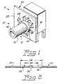
- FIG. 1 an assemblage 8 comprised of an electrical connector or insert 10 having body 12 with a tubular projection 14 having a push-through portion 16 having a first diameter and an engaging portion 18 having a second diameter larger than the first diameter.
- a support 20 for the electrical connector has a major part 22 that is substantially rigid and includes an aperture 24 formed by a plurality of deflectable spokes or beams 26.
- the support is preferably made from Sn/Pb plated steel.
- the aperture 24 has a center opening 28 with a third diameter that is greater than the first diameter and less than the second diameter, whereby the tubular projection push-through portion 16 slides through the aperture 24 and the spokes 26 engage the second diameter of the engaging portion 18 and mount said electrical connector 10 with the support 20.
- a stop 30 (see particularly Fig. 3) which, in a preferred embodiment, can be another diameter formed behind the engaging portion 18, limits the amount of insertion of the electrical connector into the support 20.
- the spokes 26 are formed to diverge away from the plane of the major part 22 of the support 20 to aid in the insertion process.
- the spokes will actually dig into the cast insert body as it relaxes from the heat applied during a soldering operation allowing the support/insert interface to remain tightly assembled and provide good and continuing ground connection for the connector.
Landscapes
- Details Of Connecting Devices For Male And Female Coupling (AREA)
- Coupling Device And Connection With Printed Circuit (AREA)
- Fastening Of Light Sources Or Lamp Holders (AREA)
Applications Claiming Priority (2)
| Application Number | Priority Date | Filing Date | Title |
|---|---|---|---|
| US737048 | 1991-07-29 | ||
| US10/737,048 US7963498B2 (en) | 2003-12-16 | 2003-12-16 | Bracket assembly |
Publications (2)
| Publication Number | Publication Date |
|---|---|
| EP1544962A1 true EP1544962A1 (de) | 2005-06-22 |
| EP1544962B1 EP1544962B1 (de) | 2006-07-26 |
Family
ID=34523138
Family Applications (1)
| Application Number | Title | Priority Date | Filing Date |
|---|---|---|---|
| EP04029474A Expired - Lifetime EP1544962B1 (de) | 2003-12-16 | 2004-12-13 | Halterungsanordnung |
Country Status (5)
| Country | Link |
|---|---|
| US (1) | US7963498B2 (de) |
| EP (1) | EP1544962B1 (de) |
| KR (1) | KR20050061320A (de) |
| CA (1) | CA2482228A1 (de) |
| DE (1) | DE602004001661T2 (de) |
Cited By (1)
| Publication number | Priority date | Publication date | Assignee | Title |
|---|---|---|---|---|
| WO2015069589A1 (en) | 2013-11-05 | 2015-05-14 | Commscope Technologies Llc | Float plate for blind matable electrical cable connectors |
Families Citing this family (7)
| Publication number | Priority date | Publication date | Assignee | Title |
|---|---|---|---|---|
| US8857632B2 (en) * | 2009-04-23 | 2014-10-14 | Big Time Jersey, Llc | Jersey hanger assembly and jersey display |
| US8973216B1 (en) * | 2011-09-01 | 2015-03-10 | Ralph M. Ramirez | Grommet |
| DE102011120683A1 (de) | 2011-12-09 | 2012-07-05 | Daimler Ag | Montageclips für eine Schellenverschraubung |
| DK2835878T3 (da) * | 2013-08-05 | 2019-06-24 | Phoenix Contact Connector Tech Gmbh | Indkapslet skrue forbindelse for en elektrisk terminal |
| EP3464975A1 (de) | 2016-06-06 | 2019-04-10 | Spider Clip L.L.C. | Wasserleitungshalterung |
| DE102017127185A1 (de) * | 2017-11-17 | 2019-05-23 | ACO Severin Ahlmann GmbH & Co Kommanditgesellschaft | Verbundelement für den Hochbau oder Tiefbau und Verwendung von einem als Klemmelement ausgebildeten Befestigungselement |
| US11047139B2 (en) | 2019-07-09 | 2021-06-29 | Schluter Systems L.P. | Veneer profile with fastening feature and related methods |
Citations (2)
| Publication number | Priority date | Publication date | Assignee | Title |
|---|---|---|---|---|
| GB444941A (en) * | 1934-09-06 | 1936-03-31 | United Carr Fastener Corp | Improvements in or relating to electric lamp sockets |
| US2452917A (en) * | 1944-06-26 | 1948-11-02 | Gen Electric | Electrode contact |
Family Cites Families (11)
| Publication number | Priority date | Publication date | Assignee | Title |
|---|---|---|---|---|
| US3351974A (en) * | 1965-12-30 | 1967-11-14 | United Carr Inc | Self-securing grommet |
| US3516111A (en) * | 1967-12-22 | 1970-06-23 | Heyman Mfg Co | Universal bushing |
| US3788655A (en) * | 1972-07-10 | 1974-01-29 | Gen Motors Corp | Grommet sealing arrangement |
| US4299363A (en) * | 1979-10-26 | 1981-11-10 | Raco, Inc. | Connector for non-metallic sheathed cable |
| US4490576A (en) * | 1981-08-10 | 1984-12-25 | Appleton Electric Co. | Connector for use with jacketed metal clad cable |
| US4903921A (en) * | 1988-12-28 | 1990-02-27 | Logsdon Foundation | Pipe holders |
| US5702076A (en) * | 1994-08-30 | 1997-12-30 | Ips Corporation | Insulator for mounting pipe in metal wall stud |
| US5653147A (en) * | 1995-08-10 | 1997-08-05 | Teleflex Incorporated | Expandable retainer for conduit end fitting |
| US6189407B1 (en) * | 1996-10-09 | 2001-02-20 | Dura Automotivesystems, Inc. | Expanding lock control cable end fitting |
| US6041618A (en) * | 1997-10-31 | 2000-03-28 | Automotive Fluid Systems, Inc. | Insulated pressure vessel holder |
| US6494508B1 (en) * | 1999-11-23 | 2002-12-17 | E. J. Brooks Company | Tamper evident security seal |
-
2003
- 2003-12-16 US US10/737,048 patent/US7963498B2/en not_active Expired - Fee Related
-
2004
- 2004-09-23 CA CA002482228A patent/CA2482228A1/en not_active Abandoned
- 2004-12-13 DE DE602004001661T patent/DE602004001661T2/de not_active Expired - Fee Related
- 2004-12-13 EP EP04029474A patent/EP1544962B1/de not_active Expired - Lifetime
- 2004-12-14 KR KR1020040105283A patent/KR20050061320A/ko not_active Withdrawn
Patent Citations (2)
| Publication number | Priority date | Publication date | Assignee | Title |
|---|---|---|---|---|
| GB444941A (en) * | 1934-09-06 | 1936-03-31 | United Carr Fastener Corp | Improvements in or relating to electric lamp sockets |
| US2452917A (en) * | 1944-06-26 | 1948-11-02 | Gen Electric | Electrode contact |
Cited By (2)
| Publication number | Priority date | Publication date | Assignee | Title |
|---|---|---|---|---|
| WO2015069589A1 (en) | 2013-11-05 | 2015-05-14 | Commscope Technologies Llc | Float plate for blind matable electrical cable connectors |
| EP3066726A4 (de) * | 2013-11-05 | 2017-06-07 | CommScope Technologies LLC | Schwimmerplatte für stromkabel-blindstecker |
Also Published As
| Publication number | Publication date |
|---|---|
| EP1544962B1 (de) | 2006-07-26 |
| DE602004001661D1 (de) | 2006-09-07 |
| US7963498B2 (en) | 2011-06-21 |
| KR20050061320A (ko) | 2005-06-22 |
| US20050127247A1 (en) | 2005-06-16 |
| CA2482228A1 (en) | 2005-06-16 |
| DE602004001661T2 (de) | 2006-11-30 |
Similar Documents
| Publication | Publication Date | Title |
|---|---|---|
| US7963498B2 (en) | Bracket assembly | |
| JP2001283990A (ja) | ノイズ除去部材及び導電性線材とノイズ除去部材との取付構造 | |
| US9893439B2 (en) | Terminal fitting with wire connection portion | |
| JP7816912B2 (ja) | 高電流印加用コンタクトアセンブリ | |
| CA2425339A1 (en) | Coaxial connector | |
| US20110148555A1 (en) | Linear solenoid for vehicle | |
| EP0105766A1 (de) | Buchse für elektrischen Verbinder und sein Herstellungsverfahren | |
| US6464546B2 (en) | Electrical contacts | |
| JP2777666B2 (ja) | Emiシールド付電気コネクタ | |
| US4434552A (en) | Method of making a pin type electrical connector contact | |
| US6537092B2 (en) | Arc discharge suppressive connector | |
| JP2006278336A (ja) | 電気コネクタージャック | |
| EP0853263A3 (de) | Anschluss für Uhrenarmband | |
| US7108406B2 (en) | Terminal retainer and strobe device using the retainer | |
| CN113574742A (zh) | 单体插座触头 | |
| JPH10223297A (ja) | 単体防水クリンプコネクタ | |
| JPH08298146A (ja) | 給電コネクタ | |
| JP2010061872A (ja) | 端子金具および端子金具付き電線 | |
| US20010019921A1 (en) | Contact socket | |
| JP2001326000A (ja) | 圧縮分岐スリーブ | |
| EP1239547A3 (de) | Elektrischer Kontakt, insbesonder Kontaktstift | |
| JP3049391U (ja) | コネクタ | |
| JP3038534B2 (ja) | コネクタ | |
| JP2004193090A (ja) | 同軸ケーブル用プラグ | |
| US1594406A (en) | Cikcuit-cohtim triltg device |
Legal Events
| Date | Code | Title | Description |
|---|---|---|---|
| PUAI | Public reference made under article 153(3) epc to a published international application that has entered the european phase |
Free format text: ORIGINAL CODE: 0009012 |
|
| AK | Designated contracting states |
Kind code of ref document: A1 Designated state(s): AT BE BG CH CY CZ DE DK EE ES FI FR GB GR HU IE IS IT LI LT LU MC NL PL PT RO SE SI SK TR |
|
| AX | Request for extension of the european patent |
Extension state: AL BA HR LV MK YU |
|
| 17P | Request for examination filed |
Effective date: 20050711 |
|
| GRAP | Despatch of communication of intention to grant a patent |
Free format text: ORIGINAL CODE: EPIDOSNIGR1 |
|
| AKX | Designation fees paid |
Designated state(s): BE DE FR GB IT NL |
|
| GRAS | Grant fee paid |
Free format text: ORIGINAL CODE: EPIDOSNIGR3 |
|
| GRAA | (expected) grant |
Free format text: ORIGINAL CODE: 0009210 |
|
| AK | Designated contracting states |
Kind code of ref document: B1 Designated state(s): BE DE FR GB IT NL |
|
| REG | Reference to a national code |
Ref country code: GB Ref legal event code: FG4D |
|
| REF | Corresponds to: |
Ref document number: 602004001661 Country of ref document: DE Date of ref document: 20060907 Kind code of ref document: P |
|
| PGFP | Annual fee paid to national office [announced via postgrant information from national office to epo] |
Ref country code: BE Payment date: 20061218 Year of fee payment: 3 |
|
| PGFP | Annual fee paid to national office [announced via postgrant information from national office to epo] |
Ref country code: FR Payment date: 20061222 Year of fee payment: 3 |
|
| ET | Fr: translation filed | ||
| PLBE | No opposition filed within time limit |
Free format text: ORIGINAL CODE: 0009261 |
|
| STAA | Information on the status of an ep patent application or granted ep patent |
Free format text: STATUS: NO OPPOSITION FILED WITHIN TIME LIMIT |
|
| PG25 | Lapsed in a contracting state [announced via postgrant information from national office to epo] |
Ref country code: DE Free format text: LAPSE BECAUSE OF NON-PAYMENT OF DUE FEES Effective date: 20070703 |
|
| 26N | No opposition filed |
Effective date: 20070427 |
|
| BERE | Be: lapsed |
Owner name: *OSRAM SYLVANIA INC. Effective date: 20071231 |
|
| PG25 | Lapsed in a contracting state [announced via postgrant information from national office to epo] |
Ref country code: BE Free format text: LAPSE BECAUSE OF NON-PAYMENT OF DUE FEES Effective date: 20071231 |
|
| REG | Reference to a national code |
Ref country code: FR Ref legal event code: ST Effective date: 20081020 |
|
| PG25 | Lapsed in a contracting state [announced via postgrant information from national office to epo] |
Ref country code: FR Free format text: LAPSE BECAUSE OF NON-PAYMENT OF DUE FEES Effective date: 20071231 |
|
| GBPC | Gb: european patent ceased through non-payment of renewal fee |
Effective date: 20081213 |
|
| NLV4 | Nl: lapsed or anulled due to non-payment of the annual fee |
Effective date: 20090701 |
|
| PGFP | Annual fee paid to national office [announced via postgrant information from national office to epo] |
Ref country code: IT Payment date: 20071231 Year of fee payment: 4 |
|
| PG25 | Lapsed in a contracting state [announced via postgrant information from national office to epo] |
Ref country code: NL Free format text: LAPSE BECAUSE OF NON-PAYMENT OF DUE FEES Effective date: 20090701 Ref country code: GB Free format text: LAPSE BECAUSE OF NON-PAYMENT OF DUE FEES Effective date: 20081213 |
|
| PG25 | Lapsed in a contracting state [announced via postgrant information from national office to epo] |
Ref country code: IT Free format text: LAPSE BECAUSE OF NON-PAYMENT OF DUE FEES Effective date: 20081213 |