EP1545096A1 - Dispositif et procédé pour réaliser des services de VoIP - Google Patents
Dispositif et procédé pour réaliser des services de VoIP Download PDFInfo
- Publication number
- EP1545096A1 EP1545096A1 EP04030019A EP04030019A EP1545096A1 EP 1545096 A1 EP1545096 A1 EP 1545096A1 EP 04030019 A EP04030019 A EP 04030019A EP 04030019 A EP04030019 A EP 04030019A EP 1545096 A1 EP1545096 A1 EP 1545096A1
- Authority
- EP
- European Patent Office
- Prior art keywords
- terminal
- port information
- information
- address
- port
- Prior art date
- Legal status (The legal status is an assumption and is not a legal conclusion. Google has not performed a legal analysis and makes no representation as to the accuracy of the status listed.)
- Granted
Links
Images



Classifications
-
- H—ELECTRICITY
- H04—ELECTRIC COMMUNICATION TECHNIQUE
- H04L—TRANSMISSION OF DIGITAL INFORMATION, e.g. TELEGRAPHIC COMMUNICATION
- H04L12/00—Data switching networks
- H04L12/66—Arrangements for connecting between networks having differing types of switching systems, e.g. gateways
-
- H—ELECTRICITY
- H04—ELECTRIC COMMUNICATION TECHNIQUE
- H04L—TRANSMISSION OF DIGITAL INFORMATION, e.g. TELEGRAPHIC COMMUNICATION
- H04L61/00—Network arrangements, protocols or services for addressing or naming
- H04L61/09—Mapping addresses
- H04L61/25—Mapping addresses of the same type
- H04L61/2503—Translation of Internet protocol [IP] addresses
- H04L61/2514—Translation of Internet protocol [IP] addresses between local and global IP addresses
-
- H—ELECTRICITY
- H04—ELECTRIC COMMUNICATION TECHNIQUE
- H04L—TRANSMISSION OF DIGITAL INFORMATION, e.g. TELEGRAPHIC COMMUNICATION
- H04L61/00—Network arrangements, protocols or services for addressing or naming
-
- H—ELECTRICITY
- H04—ELECTRIC COMMUNICATION TECHNIQUE
- H04L—TRANSMISSION OF DIGITAL INFORMATION, e.g. TELEGRAPHIC COMMUNICATION
- H04L61/00—Network arrangements, protocols or services for addressing or naming
- H04L61/09—Mapping addresses
- H04L61/25—Mapping addresses of the same type
- H04L61/2503—Translation of Internet protocol [IP] addresses
- H04L61/2521—Translation architectures other than single NAT servers
- H04L61/2528—Translation at a proxy
-
- H—ELECTRICITY
- H04—ELECTRIC COMMUNICATION TECHNIQUE
- H04L—TRANSMISSION OF DIGITAL INFORMATION, e.g. TELEGRAPHIC COMMUNICATION
- H04L61/00—Network arrangements, protocols or services for addressing or naming
- H04L61/09—Mapping addresses
- H04L61/25—Mapping addresses of the same type
- H04L61/2596—Translation of addresses of the same type other than IP, e.g. translation from MAC to MAC addresses
-
- H—ELECTRICITY
- H04—ELECTRIC COMMUNICATION TECHNIQUE
- H04L—TRANSMISSION OF DIGITAL INFORMATION, e.g. TELEGRAPHIC COMMUNICATION
- H04L65/00—Network arrangements, protocols or services for supporting real-time applications in data packet communication
- H04L65/10—Architectures or entities
- H04L65/102—Gateways
- H04L65/1043—Gateway controllers, e.g. media gateway control protocol [MGCP] controllers
-
- H—ELECTRICITY
- H04—ELECTRIC COMMUNICATION TECHNIQUE
- H04L—TRANSMISSION OF DIGITAL INFORMATION, e.g. TELEGRAPHIC COMMUNICATION
- H04L65/00—Network arrangements, protocols or services for supporting real-time applications in data packet communication
- H04L65/1066—Session management
- H04L65/1069—Session establishment or de-establishment
-
- H—ELECTRICITY
- H04—ELECTRIC COMMUNICATION TECHNIQUE
- H04L—TRANSMISSION OF DIGITAL INFORMATION, e.g. TELEGRAPHIC COMMUNICATION
- H04L65/00—Network arrangements, protocols or services for supporting real-time applications in data packet communication
- H04L65/1066—Session management
- H04L65/1101—Session protocols
-
- H—ELECTRICITY
- H04—ELECTRIC COMMUNICATION TECHNIQUE
- H04M—TELEPHONIC COMMUNICATION
- H04M7/00—Arrangements for interconnection between switching centres
- H04M7/006—Networks other than PSTN/ISDN providing telephone service, e.g. Voice over Internet Protocol (VoIP), including next generation networks with a packet-switched transport layer
-
- H—ELECTRICITY
- H04—ELECTRIC COMMUNICATION TECHNIQUE
- H04L—TRANSMISSION OF DIGITAL INFORMATION, e.g. TELEGRAPHIC COMMUNICATION
- H04L2101/00—Indexing scheme associated with group H04L61/00
- H04L2101/60—Types of network addresses
- H04L2101/618—Details of network addresses
- H04L2101/65—Telephone numbers
Definitions
- the present invention relates to an apparatus and method for providing VoIP service and, more specifically, to an apparatus and method for providing a private network with VoIP service, where an IP terminal included in the private network and an IP terminal included in a public network set a call therebetween and exchange a voice packet according to the VoIP.
- VoIP Voice over Internet Protocol
- VoIP service provides a phone user with long distance call service or international call service in an Internet environment or an Intranet environment with a local phone service fare, by integrating the phone service using an IP network.
- SIP Session Initiation Protocol
- MGCP Media Gateway Control Protocol
- H.323 H.323
- the SIP is a simple text-based application-layer control protocol, with which at least one of the participants generates, corrects or terminates a session all together.
- Such session includes Internet-based video conference, telephone, interview, event notification, and instant messaging.
- An MGCP is a standard protocol for signal operation and session management needed in progress of a multimedia conference, which is also known as 'H.248' or 'Megaco'.
- the H.323 is a standard defined by 'ITU-T' in order to transmit data of the multimedia video conference through a network of a packet exchange scheme such as TCP/IP.
- the IP network having a general public network includes a private network using a private IP addresses, a public network using a public IP addresses, a network address converter for converting the private IP addresses used in the private network to a corresponding public IP addresses, and a switching system.
- the private IP terminal When a user uses VoIP service through the private IP terminal in the IP network, the private IP terminal generates a call connection request message according to phone number information inputted by the user and transmits the message to the IP network.
- the network address converter converts a source IP address in the call connection request message transmitted from the private IP terminal, that is, converts the address from the private IP address to a corresponding public IP address.
- the switching system identifies an incoming IP address of a call connection request message transmitted from the network address converter, and transmits the call connection request message to the corresponding IP terminal.
- the public IP terminal responds to the call connection request message, a call is connected between the private IP terminal and the public IP terminal, and voice communication is performed according to the VoIP.
- a private IP terminal is connected to another private network. That is, when a plurality of private IP terminals or PCs are connected to each other through a private network, the network address converter converts the source IP address of the message transmitted from each of the private IP terminals or PCs into the same public IP address. Since a destination IP address of a packet transmitted from the public IP terminal is a public IP address that is converted by the network address converter, it is not possible to transmit such a packet to a specific private IP terminal or PC. Therefore, it is not possible to provide VoIP service between a public IP terminal and a private IP terminal.
- the switching system identifies an incoming public IP address transmitted from the public IP terminal, and transmits the call connection request message to the network address converter.
- the network address converter cannot convert the public IP address to the private IP address since it cannot uniquely determine which specific private IP terminal or PC is to receive the call connection request message transmitted from the public IP terminal.
- the public IP terminal cannot transmit a call connection request message to an incoming private IP terminal, making it impossible to provide VoIP service between a public IP terminal and a private IP terminal. What is therefore needed is an apparatus and method for providing VoIP service between public IP terminals and private IP terminals.
- a system having at least one IP terminal for generating a test message including port information used when exchanging a packet and providing the message to a network, when the IP terminals are connected to the network and a switching system for storing and managing the port information of each of the IP terminals through the test message provided from the IP terminal, transmitting the port information of the other IP terminal to any one of an outgoing terminal and an incoming IP terminal in a case that VoIP service for the IP terminal included in a private network is requested, and allowing each of the IP terminals to exchange the packet using the transmitted port information.
- the system for providing VoIP service further includes an address conversion unit for converting a private IP address set in the test message to a corresponding public IP address when the IP terminal is connected to the private network.
- the address conversion unit stores public IP address information corresponding to private IP address information of the IP terminal connected to the private network and port information corresponding to the port information of the corresponding IP terminal, and changes the private IP address information to the corresponding public IP address information and the port information to the corresponding port information, when the test message or voice packet are transmitted from the IP terminal.
- the IP terminal includes a storage unit for storing IP address information, port information and phone number information of the IP terminal, a message generation unit for periodically generating the test message using each information stored in the storage unit, a packet processing unit for, when a call is set to the other IP terminal, generating the voice packet to receive the VoIP service and transmitting the voice packet using address information and port information of the other IP terminal, and a network interface for outputting the test message and the voice packet through the network.
- a storage unit for storing IP address information, port information and phone number information of the IP terminal
- a message generation unit for periodically generating the test message using each information stored in the storage unit
- a packet processing unit for, when a call is set to the other IP terminal, generating the voice packet to receive the VoIP service and transmitting the voice packet using address information and port information of the other IP terminal
- a network interface for outputting the test message and the voice packet through the network.
- the switching system includes a reception unit for receiving the test message, voice packet and VoIP service request message transmitted from the IP terminal, a port management unit for managing phone number information, IP address information and port information of the corresponding IP terminal through the test message received by the reception unit, a storage unit for storing each information managed in the port management unit, and a port processing unit for, when a VoIP service request message is transmitted from the outgoing IP terminal, searching for the port information of the outgoing IP terminal from the storage unit, including the searched port information in the VoIP service request message and transmitting the VoIP service request message to the incoming IP terminal, and for, when a response message is transmitted from the incoming IP terminal, searching for the port information of the incoming IP terminal from the storage unit, including the searched port information in the response message, and transmitting the response message to the outgoing IP terminal.
- a reception unit for receiving the test message, voice packet and VoIP service request message transmitted from the IP terminal
- a port management unit for managing phone number information, IP address information and port information of the corresponding IP terminal through the test message received by the
- an IP terminal for providing VoIP service, the IP terminal having a user interface for providing an input signal and a voice signal according to user's selection, a memory for storing port information of the IP terminal, a message generation unit for generating a test message including the port information stored in the memory, a VoIP service request message according to the input signal provided from the user interface, and a voice packet according to the voice signal; and a packet exchange unit for transmitting each message generated in the message generation unit from the switching system, identifying the port information included in each message when receiving the VoIP service request message or a response message, and transmitting the voice packet generated in the message generation unit using the port information when a call is connected to the other IP terminal.
- an address conversion unit for interworking between a private network with a public network, the address conversion unit having a storage unit for storing public IP address information corresponding to private IP address information of a private IP terminal connected to the private network, and port information corresponding to port information of the corresponding IP terminal, and an address processing unit for, when a packet is received from the private IP terminal, changing the private IP address to a corresponding public IP address and transmitting a packet of port information corresponding to the port information in which the packet is received, and for, when a packet is received from the public network, searching for the private IP address corresponding to a destination IP address and port information corresponding to the port information in which the packet is received, and transmitting the packet to the private IP address using the searched port information.
- a switching system connected to a plurality of IF terminals, the switching system having a message reception unit for receiving a test message including port information, a VoIP service request message and a response message from each of the IP terminals, a port management unit for managing the port information of the corresponding IP terminal when the test message is received by the message reception unit, and a message transmission unit for, when a VoIP service request signal is transmitted from an arbitrary outgoing IP terminal through the message reception unit, searching for port information of the outgoing IP terminal, including the searched port information in the VoIP service request message and transmitting the message to an incoming IP terminal, and for, when a response message is transmitted from the incoming IP terminal, searching for port information of the incoming IP terminal, including the searched port information in the response message, and transmitting the response message to the outgoing IP terminal.
- a method for providing VoIP service in at least one IP terminal connected to a private network or a public network, and a system including a switching system including generating a test message including port information and transmitting the message to a network, when each of the IP terminals is connected to the network, allowing the switching system to identify the port information through the test message transmitted from the IP terminal and to manage the information as a port table, searching for the port information of an outgoing IP terminal from the port table, including the searched port information in a VoIP service request message and transmitting the request message to an incoming IP terminal, when the VoIP service request message is received from the outgoing IP terminal; searching for the port information of the incoming IP terminal, including the searched port information in a response message, and transmitting the response message to the outgoing IP terminal, when the response message is received from the incoming IP terminal, and when a call is set between each of the IP terminals, allowing each of the IP terminals to exchange a voice packet used to receive the VoIP service through port
- a method for providing VoIP service by an IP terminal connected to a switching system including generating a test message including port information used to exchange a packet and transmitting the test message to the switching system, when connected to a network, identifying port information of the other IP terminal in the message transmitted from the switching system, when the switching system connects a call to the other IP terminal, generating a voice packet to provide the VoIP service, and transmitting the voice packet to the other IP terminal through the identified port information, and outputting voice information according to the voice packet transmitted from the other IP terminal, and providing the VoIP service.
- a method for processing address information by a address conversion unit including storing private IP address information of each of private IP terminals connected to a private network, public IP address information corresponding to port information, and port information, searching for a public IP address corresponding to the private IP address information of the IP terminal and changing the IP address, when a packet is transmitted from the IP terminal, and searching for port information corresponding to the port information receiving the packet and transmitting the packet in which the IP address is changed through the searched port information.
- a method for providing VoIP service by a switching system connected to at least one IP terminal connected to a private network or a public network including identifying port information in a test message transmitted from each of the IP terminals and managing the port information as a port table, when a VoIP service request message is transmitted from an outgoing IP terminal, searching for the port information of the outgoing IP terminal, including the searched port information in the VoIP service request message, and transmitting the VoIP service request message to an incoming IP terminal; when a response message is transmitted from the incoming IP terminal, searching for the port information of the incoming IP terminal, including the searched port information in the response message, and transmitting the response message to the outgoing IP terminal; and connecting a call to provide the VoIP service between the incoming IP terminal and the outgoing IP terminal.
- FIG. 1 is a block diagram for explaining an entire construction of an IP network including a general private network.
- the IP network includes a plurality of private IP terminals 10, 11 and 12 connected to a plurality of private networks 50 and 51, a public IP terminal 13 connected to a public network 60, a PC (Personal Computer) 20, a switching system 30 and a plurality of routers 40.
- the public IP terminal 13 means an IP terminal which uses a public IP address (global IP address), and a public IP address used in the public network 60 means an IP address unique in the world, which is used after being assigned from domestic and overseas IP address management groups.
- the private IP terminals 10, 11 and 12 refer to IP terminals which are using private IP addresses, and the private addresses used in the private networks 50 and 51 refer to IP addresses whose object is to be used only in a unit or other organization.
- the PC 20 is connected to the IP network using the private IP address used in the private network 51, and provides a user with web surfing or material search service.
- the plurality of routers 40 route a receiving packet and transmit the corresponding packet to a destination.
- the router 40 changes a source IP address of the packet transmitted from the private IP terminals 10, 11 and 12 to a public IP address corresponding to the private IP address, and a destination IP address of the packet received from the public network 60 to a private IP address corresponding to the public IP address.
- the router 40 identifies a port with which each of the private IP terminals 10, 11 and 12 exchanges the packet in order that each of the private IP terminals 10, 11 and 12 receives the packet transmitted from the public network 60, and transmits the packet through the port.
- the switching system 30 identifies an incoming IP terminal 1x and switches to connect a call through an IP network between an outgoing IP terminal 1x and an incoming IP terminal 1x.
- FIG. 2 is an internal block diagram for explaining a construction of an IP terminal 10 of FIG. 1 according to a preferred embodiment of the present invention.
- the IP terminal 10 according to the present invention includes a user interface 101, a control unit 102, a memory 103 and an IP interface 104, the control unit 102 having a message processing unit 102a.
- the user interface 101 provides an input signal according to a selection of the user, and a voice signal according to voice information inputted by the user.
- the user interface 101 outputs the voice information according a voice signal provided by the other IP terminal 10 in order that the user can listen to the voice information, so that the user can perform voice communication according to VoIP.
- the memory 103 stores the public or private IP address information assigned to the IP terminal 10, along with operational information and port information of the IP terminal 10.
- the control unit 102 generates the call connection request message according to the input signal provided from the user interface 101 and transmits the message to the other IP terminal 10.
- the control unit 102 also generates a voice packet according to the voice signal provided from the user interface 101 and transmits the message to an incoming IP terminal 10 when a call for the voice communication is connected to the other IP terminal 10.
- control unit 102 When the control unit 102 receives the call connection request message from the other IP terminal 10, control unit 102 generates a response message with respect to the call connection request message, and transmits the message to the other IP terminal 10.
- the message processing unit 102a When the IP terminal 10 is connected to the switching system 30 through the IP network, the message processing unit 102a generates a link test message (LinkTestMsg) in a desired period and transmits the message to the switching system 30.
- LinkTestMsg link test message
- Information included in the link test message is phone number information of the corresponding IP terminal 10, IP address information, signaling port information, packet port information and port sort information.
- the signaling port is a port with which the IP terminal 10 exchanges a signaling message
- the packet port is a port with which the IP terminal 10 exchanges the voice packet in the state of a call connection.
- the message processing unit 102a periodically generates a link test message including all of the signaling port information and packet port information and transmits the message to the switching system 30, or periodically generates a first link test message including the signaling port information and a second link test message including the packet port information and transmits both messages to the switching system 30.
- the detailed description of the present invention explains the case that the IP terminal 10 periodically generates the first link test message including the signaling port information and the second link test message including the packet port information, and transmits both messages to the switching system 30.
- FIG. 3 is a diagram for explaining a general packet construction.
- the packet is largely divided into an Ethernet header area, an IP header area, a UDP header (or User Datagram Protocol header) area, and a data area.
- the IP header area includes a source IP address field (b) and a destination IP address field (c), and the UDP header area includes a source port field (d) and a destination port field (e).
- the source IP address field (b) sets 32-bit IP address information of the IP terminal 10, and the destination IP address field (c) sets a 32-bit IP address of the last destination of the packet.
- the source port field (d) has 16-bit port number information used to transmit data in an application, and the destination port field (e) has destination port number information of data in the application.
- the message processing unit 102a sets the private IP address information assigned by the IP terminal 10 from the private network 50 in the source IP address field (b) of the packet, public IP address of the switching system 30 in the destination IP address field (c), the signaling port information in the source port field (d), the port information of the switching system 30 in the destination port field (e), the port sort information of the source port field (d) in the data field (f), and the phone number information, and generates the first link test message in a desired period.
- the message processing unit 102a sets the private IP address information assigned from the private network 50 by the IP terminal 10 in the source IP address field (b) of the packet, the public IP address of the switching system 30 in the destination IP address field (c), the packet port information in the source port field (d), the port information of the switching system 30 in the destination port field (e), the port sort information of the source port field (b) in the data filed (f), and the phone number information, and generates the second test message in a desired period.
- the IP interface 104 performs interface of the first and second link test messages generated by the message processing unit 102a so as to be transmitted to the switching system 30 through the IP network, and transmits the call connection request message generated by the control unit 102 according to the input signal provided from the user interface 101 to the other IP terminal 10 or receives the call connection request message from the other IP terminal 10.
- the IP interface unit 104 transmits the voice packet generated by the control unit 102 to the other IP terminal 10 or receives the voice packet transmitted from the other IP terminal 10 in the state that a call is set with the other IP terminal 10.
- FIG. 4 is an internal block diagram for explaining a router construction according to a preferred embodiment of the present invention.
- the router 40 according to the present invention includes a routing processing unit 41, a storage unit 42 and a port connection unit 43.
- the routing processing unit 41 includes an address processing unit 41 a, and the storage unit 42 stores a NAT (Network Address Translation) table 42a.
- NAT Network Address Translation
- the port connection unit 43 receives a packet transmitted from the IP terminal 1x or switching system 30 through a private network 50 or a public network 60, provides a routing processing unit 41 with the packet, and transmits a packet according to a routing result of the routing processing unit 41.
- the routing processing unit 41 analyzes a header of the packet provided from the port connection unit 43, searches for a route to transmit the packet to the final destination in a forwarding table (not shown), and transmits the packet using the searched route.
- the address processing unit 41a of the routing processing unit 41 searches for a public IP address corresponding to the source IP address information included in the header of the packet received through the port connection unit 43 from the NAT table 42a, and changes a source IP address of the packet to the searched public IP address.
- FIG. 5 is a diagram for explaining a NAT table according to the present invention.
- the NAT table 42a stores signaling port information and packet information of the IP terminal 10 having one private IP address information, and signaling port information and packet port information of the router 40 of the public IP address information corresponding to the information of the IP terminal 10.
- the corresponding IP terminal 10 periodically generates the first link test message including private IP address information and signaling port information and the second link test message including the private IP address information and the packet port information, and transmits the messages to the router 40.
- the port connection unit 43 of the router 40 transmits each of the link test messages received from the private IP terminal 10 to the address processing unit 41a of the router processing unit 41.
- the address processing unit 41 a stores the private IP address and the signaling port information included in the received first link test message, and identifies the public IP information and the signaling port information in which the router 40 transmits the signaling message and stores both information, correspondingly. That is, the address processing unit 41a stores the private IP address information of '10.10.10.10' and the signaling port information of '6000', and the corresponding public IP address information of '201.111.198.40' and the signaling port information of '7500'.
- the address processing unit 41a stores the private IP address and packet port information included in the received second link test message, and identifies the corresponding public IP address and the packet port information in which the router 40 transmits the packet and stores them, correspondingly.
- the address processing unit 41a stores the private IP address information of '10.10.10.10' and the packet port information of '9000', and the corresponding public IP address information of '201.111.198.40', and the packet port information of '7600'.
- the address processing unit 41a changes the private IP address information set in the source IP address field (b) transmitted from the private IP terminal 10 to the public IP address stored in the NAT table 42a correspondingly, searches for the port information corresponding to the port information set in the source port field (d) from the NAT table 42a, and transmits the packet through the searched port.
- the address processing unit 41a identifies the IP address information set in the destination IP address field (c) of the packet received through the public network 60 and the port information set in the destination port field (e), and searches for the private IP address information and port information stored in the NAT table 42a, correspondingly.
- the address processing unit 41a sets the private address information searched in the NAT table 42a in the destination address field (c) of the packet and transmits the information to the destination IP terminal 10 through the searched port.
- FIG. 6 is an internal block diagram for explaining a construction of a switching system 30 according to a preferred embodiment of the present invention.
- the switching system 30 includes a switching control unit 31, a network interface 33, and a database DB 32, the switching control unit 31 includes a port management unit 31a, and the data base 32 stores a port table 32a.
- the network interface 33 receives a link test message, a voice packet and a call connection request message transmitted from the router 40 or the public IP terminal 13 through the public network 60, and provides the switching control unit 31 with them.
- the network interface 33 transmits the voice packet and call connection request message to the destination IP terminal according to the switching of the switching control unit 31.
- the switching control unit 31 identifies the incoming IP terminal 1x of the call connection request message received through the network interface 33, switches the call connection message to the incoming IP terminal lx, and transmits a response message to the call connection request message received from the incoming IP terminal 1x to the outgoing IP terminal 1x.
- the switching control unit 31 When the call for the voice communication is connected to the incoming IP terminal lx, the switching control unit 31 connects the call for voice communication to the outgoing IP terminal lx, and connects the call between the incoming IP terminal 1x and the outgoing IP terminal 1x.
- the switching control unit 31 performs the switching to transmit the voice packet transmitted from the outgoing IP terminal 1x to the incoming IP terminal 1x in the state that the call is connected between the incoming IP terminal 1x and the outgoing IP terminal lx, and to transmit the voice packet transmitted from the incoming IP terminal 1x to the outgoing IP terminal 1x.
- the port management unit 31a of the switching control unit 31 identifies phone number information, public IP address information and port information included in the link test message received through the network interface 33, generates the port table 32a, and stores the table in the database 32.
- FIG. 7 is a diagram for explaining a port table according to a preferred embodiment of the present invention.
- phone number information of the IP terminal lx, public IP address information of the IP terminal lx, signaling port information and packet port information are stored in the port table 32a. That is, the port management unit 31a identifies the IP address information from the source IP address field (b) of the first link test message received from the network interface 33, signaling information from the source port field (d) and phone number information from the data field (f), and stores the information in the port table 32a.
- the port management unit 31a identifies the IP address information from the source IP address field (b) of the second link test message received through the network interface 33, the packet port information from the source port field (d), and phone number information from the data field (f), and stores the information in the port table 32a.
- the port management unit 31a identifies the IP address of the incoming IP terminal 1x of the call connection request message transmitted from the IP terminal 1x through the network interface 33, and transmits the public IP address information together with packet port information of the outgoing IP terminal 1x while it transmits the call connection request message to the corresponding incoming IP terminal 1x.
- the public IP address information and the packet port information of the incoming IP terminal 1x are together transmitted to the outgoing IP terminal 1x.
- the incoming IP terminal 1x transmits the voice packet using the packet port information and the IP address of the outgoing IP terminal 1x transmitted together with the call connection request message
- the outgoing IP terminal 1x transmits the voice packet using the packet port information and the IP address information of the incoming IP terminal 1x transmitted together with the response message.
- FIG. 8 is a flow chart for explaining a method for managing a port table for each of IP terminals according to a preferred embodiment of the present invention.
- the IP terminal 1x is connected to the switching system 30 through the IP network (S1).
- Each of the IP terminals 1x periodically generates the first and second link test messages, and transmits the messages to the switching system 30 (S2).
- a router #3 40 transmits the first and second link test messages transmitted from the public IP terminal 13 to the switching system 30.
- a router #1 40 or a router #2 40 changes the private IP address set in the source IP address field (b) of the first and second link test messages transmitted from the private IP terminals 10, 11 and 12 to a corresponding public IP address, and port information set in the source port field (d) to corresponding port information (S3).
- the router 40 transmits the first and second link test messages where the IP address information and port information are changed, to the switching system 30 (S4).
- the switching system 30 manages the port table 32a using the phone number information, the IP address information, the signaling port information and the packet port information included in the first and second link test messages transmitted from the router 40 or the public IP terminal 13 (S5).
- the NAT table 42a shown in FIG. 5 is stored in the router 40, and the private IP terminal #1 (10) whose private IP address is '10.10.10.10', whose signaling port information is '6000', whose packet port information is '9000' transmits the first and second link messages.
- FIGS. 9A and 9B are diagrams for explaining a construction of first and second link test messages respectively that a private IP terminal transmits according to an embodiment of the present invention.
- the message processing unit 102a of the private IP terminal #1 (10) periodically sets the private IP address of '10.10.10.10' in the source IP address field (b), the public IP address of the switching system 30 of '201.111.198.30' in the destination IP address field (c)', the signaling port information of the private IP terminal of '6000' in the source port field (d), the destination port information in the destination port field (e), and the phone number information of '3100' and the port sort information set in the source port field (d) in the data field (f), generates the first link test message periodically, and transmits the generated first link test message to the router #1 (40), as shown in FIG. 9A.
- the message processing unit 102a periodically sets the private IP address of ' 10.10.10.10' in the source IP address field (b), the public IP address of the switching system of '201.111.198.30' in the destination IP address field (c), the packet port information of the private IP terminal #1 (10) of '9000' in the source port field (d), the destination port information in the destination port field (e), the phone number of '3100' in the data field (f), and the port sort information set in the source port field (d), generates the second link test message, and transmits the generated second link test message to the router #1 (40), as shown in FIG. 9B.
- the port connection unit 43 of the router 40 provides the address processing unit 41a with the second link test message transmitted from the private IP terminal #1 (10).
- the address processing unit 41 a identifies the private IP address information and port information of the private IP terminal #1 (10) from the source IP address field (b), the source port field (d) and the data field (f) of the first and second link test messages received from the port connection unit 43.
- the address processing unit 41a searches for the private IP address information identified from the NAT table 42a, the public IP address information corresponding to the port information, and the port information.
- the address processing unit 41 a sets the public IP address information and port information searched from the NAT table 42a in the source IP address field (b) and the source port field (d), and transmits the information to the switching system 30.
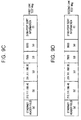
- FIGS. 9C and 9D are diagrams for explaining first and second link test messages respectively transmitted by a router in accordance an embodiment of the present invention.
- the address processing unit 41 a of the router 40 searches for the port information corresponding to '6000' set in the source port field (d) of the first link test message transmitted from the private IP terminal #1 (10) from the NAT table 42a, and sets the searched '7500' in the source port field (d).
- the address processing unit 41 a searches for the public IP address corresponding to the private IP address '10.10.10.10' set in the source IP address field (b) of the first link test message from the NAT table 42a, sets the searched public IP address '201.111.198.40' in the source IP field (b), and transmits the address to the switching system 30.
- the address processing unit 41 a searches for the public IP address corresponding to the '10.10.10.10' set in the source IP field (d) of the second link test message transmitted from the private IP terminal #1 (10) from the NAT table 42a, and sets the searched '201.111.198.40' in the source IP address field (b).
- the address processing unit 41 a searches for the port information corresponding to the '9000' set in the source port field (d) of the second link test message from the NAT table 42a, sets the searched '7600' in the source port field (d), and transmits the switching system 30.
- the address processing unit 41 a identifies the port sort information stored in the data field (f) of the first and second link test messages, and determines whether the port information set in the source port field (d) of the first and second link test messages are the signaling port information or the packet port information.
- the network interface 33 of the switching system 30 provides the port management unit 31a with the first and second link test messages transmitted form the router 40.
- the port management unit 31a identifies the IP address information, the port information and the phone number information set in the source IP field (b), the source port field (d), and the data field (f) of the received first and second link test messages, and generates the port table 32a as shown in FIG. 7. That is, the port management unit 31a identifies the phone number information of the private IP terminal #1 (10) from the data field (f) of the first link test message transmitted from the router 40, the public IP address information from the source IP address field (b), and the signaling port information from the source port field (d). The port management unit 31a generates the port table 32a using each information of the identified private IP terminal #1 (10) and stores the table in the database 32.
- the port management unit 31 a identifies the port sort information stored in the data field (f) of the received link test message, and determines whether the port information set in the source port field (d) is the signaling port information or the packet port information.
- the port management unit 31a identifies the phone number information of the private IP terminal #1 (10) from the data field (f) of the second link test message transmitted from the router 40 and the public IP address information from the source IP address field (b), and the packet port information from the source port field (d).
- the port management unit 31 a generates the port table 32a and stores the table in the database 32 using each of information of the identified private IP terminal #1 (10).
- FIG. 10 is a flow chart for explaining a method for providing a private IP terminal connected to a private network with VoIP service according to a preferred embodiment of the present invention.
- the public IP terminal using the public IP address transmits a call connection request signal to the private IP terminal which uses the private IP address
- the same is applied to the case where other private IP terminals transmit the call connection request signal to the public IP terminal or where the private IP terminal transmits the call connection request signal to the other IP terminals.
- each of the IP terminals 1x is connected to the switching system 30 and the signaling and packet ports through the IP network, and transmits the first and second link test messages.
- the switching system 30 stores the port table 32a in the database 32 as shown in FIG. 7 (S10).
- the public IP terminal 13 transmits the call connection request message to make the voice communication to the private IP terminal #1 (10) to the switching system 30 according to user's selection (S11).
- the control unit 102 of the public IP terminal 13 generates the call connection request signal including the phone number information of the public IP terminal #1 (13) of '3100' according to an input signal provided from the user interface 101, and transmits the signal to the switching system 30.
- the network interface 33 of the switching system 30 provides the switching control unit 31 with the call connection request message transmitted from the public IP terminal 13, and the port management unit 31a searches for the public IP address information of the private IP terminal #1(10) corresponding to the phone number information of '3100' and the signaling port information included in the call connection request message (S12).
- the port management unit 31a includes the packet port information of the public IP terminal 13 in the call connection request message, and transmits the message to the public IP address '201.111.198.40' through the searched signaling port information '7500'.
- the address processing unit 41a of the router #1 (40) searches for the private IP address corresponding the public IP address information of the call connection request message transmitted from the switching system 30 from the stored NAT table 42a as shown in FIG. 5, and signaling port information corresponding to the signaling port information.
- the address processing unit 41 a transmits the call connection request message from the NAT table 42a to the private IP address information '10.10.10.10' through the searched signaling port information '6000' (S13).
- the private IP terminal #1 (10) whose private IP address is '10.10.10.10' identifies the packet port information '9000' of the public IP terminal 13 included in the call connection request message transmitted from the router #1(40), generates a response message with respect to the call connection request message, and transmits the response message to the router #1(40) through the '6000' port (S14).
- the router #1 (40) transmits the response message transmitted from the private IP terminal #1(10) to the switching system 30 through a '7500' port.
- the address processing unit 41 a of the router # 1(40) searches for the public IP address corresponding to the private IP address '10.10.10.10', and transmits the response message to the switching system 30 with the searched public IP address '201.111.198.40' as the source IP address.
- port management unit 31 a of the switching system 30 receives the response message from the router #1(40), it searches for the packet port information of the private IP terminal #1(10) from the port table 32a, includes the searched packet port information '7600' in the response message, and transmits the message to the public IP terminal 13 (S 15).
- the public IP terminal 13 identifies the packet port information of the private IP terminal #1(10) included in the response message.
- the switching system 30 connects the call to the public IP terminal 13, and the call for voice communication between the private IP terminal #1(10) and the public IP terminal 13 (S16).
- the public IP terminal 13 transmits the voice packet to a packet port of the private IP terminal #1(10) identified from the response message.
- the private IP terminal #1(10) transmits the voice packet to a packet port of the public IP terminal 13 identified from the call connection request message (S17). Accordingly, even when the private IP terminal #2(11) connected to the private network #1(50) is connected to the IP network using the same public IP address as the private IP terminal #1(10), '201.111.198.40', the private IP terminal #1(10) can exchange the voice packet through the packet port.
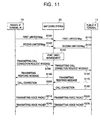
- FIG. 11 is a flow chart for explaining a method for providing VoIP service according to a preferred embodiment of the present invention.
- the private IP terminal #1(10) connected to the switching system 30 through the IP network generates the first link test message including the signaling port information in a desired period and transmits the message to the switching system (S100), and the public IP terminal 13 also generates the first link test message including the signaling port information in a desired period, and transmits the message to the switching system 30 (S110).
- the private IP terminal #1(10) generates the second link test message including the packet port information in a desired period and transmits the message to the switching system 30 (S120), and the public IP terminal also generates the second link test message including the packet port information and transmits the message to the switching system (S 130).
- the switching system 30 manages the public IP address information and each of the port information of each of the IP terminals 10 and 13 as the port table 42a as shown in FIG. 7 according to the link test message transmitted from the each of the IP terminals 1x (S140).
- the private IP terminal #1(10) generates the call connection request message according to a user's VoIP service request and transmits the message to the switching system 30 (S150).
- the private IP terminal #1(10) generates a call connection request message having the public IP address information of the public IP terminal 13 of the incoming terminal as the destination IP address and transmits the message to an adjacent router #1(40).
- the address processing unit 41a of the router #1(40) searches for the public IP address information and signaling port information of the private IP terminal 10 which has transmitted the call connection request message from the NAT table 42a, changes the source IP address included in the call connection request message to the searched public IP address information, and transmits the address information to the switching system 30 through the searched signaling port.
- the switching system 30 identifies the incoming IP terminal of the received call connection request message and transmits the call connection request message to the identified public IP terminal 13 (S160).
- the port management unit 31a of the switching system 30 identifies the outgoing phone number information included in the received call connection request message, and searches for the packet port information used by an IP terminal of the corresponding phone number from the port table 32a.
- the switching system 30 includes the searched packet port information in the call connection request message and transmits the message to the public IP terminal 13 of the incoming IP terminal. That is, since the public IP address included in the received call connection request message is '201.111.198.40', the signaling port information is '7500', and the outgoing phone number is '3100', the port management unit 31 a searches for the packet port information of the outgoing IP terminal, '7600' from the port table 42a.
- the port management unit 31a includes the packet port information '7600' in the call connection request message and transmits the information to the public IP terminal 13.
- the public IP terminal 13 receives the call connection request message, it identifies the outgoing packet port information and transmits the response message to the switching system 30 (S 170).
- the switching system 30 searches for the packet port information of the public IP terminal 13 from the port table 42a, includes the searched incoming packet port information in the response message, and transmits the message to the private IP terminal #1(10) (S180). That is, each of the IP terminals 10 and 13 provided with the VoIP service has to identify the packet port information of the other party with which the packet is exchanged. Therefore, the port management unit 31a of the switching system 30 transmits the packet port information of the outgoing IP terminal while transmitting the call connection request message to the incoming IP terminal, and includes the packet port information of the incoming IP terminal in the response message and then transmits the message to the outgoing IP terminal when the response message is received from the incoming IP terminal.
- the public IP terminal 13 connects the call to the switching system 30 (S 190)
- the switching system 30 connects the call to the private IP terminal #1(10) (S200).
- the private IP terminal #1(10) transmits the voice packet to the switching system 30 using the public IP address of the public IP terminal 13 and the packet port information included in the response message (S210).
- the switching system 30 identifies the public IP address of the destination address, and transmits the voice packet to the packet port of the public IP terminal having the public IP address (S220).
- the public IP terminal 13 transmits the voice packet to the switching system 30 using the public IP address information and the packet port information included in the call connection request message (S230).
- the switching system 30 identifies the destination IP address of the received voice packet, and transmits the voice packet to the packet port of the private IP terminal #1(10) having the IP address (S240).
- the public IP terminal transmits the voice packet to the packet port information included in the call connection request message, '7600' with the public IP address of the outgoing public IP terminal, '201.111.198.40' as a destination IP address.
- the switching system transmits the received voice packet to the destination IP address '201.111.198.40' through the '7600' port.
- the router #1(40) searches for the IP terminal which uses the '7600' port as the packet port in the NAT table 42a. According to the searched result, the packet is transmitted to the private IP terminal #1(10) whose private IP address is '10.10.10.10' through a '9000' port.
- the private IP terminal #1(10) makes the public IP address '201.111.198.20' of the incoming IP terminal as the destination IP address, and transmits the voice packet to the '9000' port of the packet port information included in the response message.
- the router #1(40) When the voice packet is received from the private IP terminal #1(10), the router #1(40) changes the source IP address of the packet header to the corresponding public IP address and transmits the address to the switching system 30.
- the switching system 30 transmits to the public IP address '201.111.198.20' of the destination IP address of the received voice packet through the '9000' port.
- a signaling message is exchanged using a signaling port between the private IP terminals or between a public IP terminal and a private IP terminal, and the voice packet is exchange through the packet port, so that a user can be provided with VoIP service through the private IP terminal.
Landscapes
- Engineering & Computer Science (AREA)
- Computer Networks & Wireless Communication (AREA)
- Signal Processing (AREA)
- Multimedia (AREA)
- Business, Economics & Management (AREA)
- General Business, Economics & Management (AREA)
- Power Engineering (AREA)
- Data Exchanges In Wide-Area Networks (AREA)
- Telephonic Communication Services (AREA)
Applications Claiming Priority (2)
| Application Number | Priority Date | Filing Date | Title |
|---|---|---|---|
| KR1020030092733A KR100552513B1 (ko) | 2003-12-17 | 2003-12-17 | 브이오아이피 서비스를 제공하는 장치 및 그 방법 |
| KR2003092733 | 2003-12-17 |
Publications (2)
| Publication Number | Publication Date |
|---|---|
| EP1545096A1 true EP1545096A1 (fr) | 2005-06-22 |
| EP1545096B1 EP1545096B1 (fr) | 2008-07-16 |
Family
ID=34511246
Family Applications (1)
| Application Number | Title | Priority Date | Filing Date |
|---|---|---|---|
| EP04030019A Expired - Lifetime EP1545096B1 (fr) | 2003-12-17 | 2004-12-17 | Dispositif et procédé pour réaliser des services de VoIP |
Country Status (6)
| Country | Link |
|---|---|
| US (1) | US7952995B2 (fr) |
| EP (1) | EP1545096B1 (fr) |
| KR (1) | KR100552513B1 (fr) |
| CN (1) | CN100588170C (fr) |
| AU (1) | AU2004233449B8 (fr) |
| DE (1) | DE602004015053D1 (fr) |
Cited By (9)
| Publication number | Priority date | Publication date | Assignee | Title |
|---|---|---|---|---|
| GB2423670A (en) * | 2005-02-28 | 2006-08-30 | Samsung Electronics Co Ltd | Exchanging packets between IP terminals in private networks connected through a public network |
| EP1841164A1 (fr) * | 2006-03-29 | 2007-10-03 | Swisscom AG | Système, procédé et dispositif de connexion pour configurer des routeurs NAT |
| WO2007103238A3 (fr) * | 2006-03-02 | 2007-11-22 | Tango Networks Inc | Système et procédé permettant de valider des positions d'appel de départ à l'aide de capacités sms et d'assistance téléphonique |
| US7843901B2 (en) | 2006-03-02 | 2010-11-30 | Tango Networks, Inc. | Call flow system and method for use in a legacy telecommunication system |
| US7873001B2 (en) | 2006-03-02 | 2011-01-18 | Tango Networks, Inc. | System and method for enabling VPN-less session setup for connecting mobile data devices to an enterprise data network |
| US7890096B2 (en) | 2006-03-02 | 2011-02-15 | Tango Networks, Inc. | System and method for enabling call originations using SMS and hotline capabilities |
| US7952995B2 (en) | 2003-12-17 | 2011-05-31 | Samsung Electronics Co., Ltd. | Apparatus and method for providing VoIP service |
| CN101442480B (zh) * | 2007-11-20 | 2011-09-07 | 迈普通信技术股份有限公司 | 基于stun协议下的网络通信的方法 |
| US8175053B2 (en) | 2006-03-02 | 2012-05-08 | Tango Networks, Inc. | System and method for enabling VPN-less session setup for connecting mobile data devices to an enterprise data network |
Families Citing this family (29)
| Publication number | Priority date | Publication date | Assignee | Title |
|---|---|---|---|---|
| JP4728586B2 (ja) * | 2004-03-16 | 2011-07-20 | Necインフロンティア株式会社 | Ip電話方法 |
| KR100738525B1 (ko) * | 2005-02-25 | 2007-07-11 | 삼성전자주식회사 | 브이오아이피 시스템에서의 호 처리장치 및 그 방법 |
| KR100694206B1 (ko) * | 2005-02-28 | 2007-03-14 | 삼성전자주식회사 | 사설망에서의 sip 서비스 제공 장치 및 그 방법 |
| KR100785294B1 (ko) * | 2005-02-28 | 2007-12-12 | 삼성전자주식회사 | 패킷 통신 서비스를 제공하는 시스템 및 그 방법 |
| US7958560B1 (en) | 2005-03-15 | 2011-06-07 | Mu Dynamics, Inc. | Portable program for generating attacks on communication protocols and channels |
| US8095983B2 (en) | 2005-03-15 | 2012-01-10 | Mu Dynamics, Inc. | Platform for analyzing the security of communication protocols and channels |
| US11405846B2 (en) | 2006-03-02 | 2022-08-02 | Tango Networks, Inc. | Call flow system and method for use in a legacy telecommunication system |
| US7958230B2 (en) | 2008-09-19 | 2011-06-07 | Mu Dynamics, Inc. | Test driven deployment and monitoring of heterogeneous network systems |
| US9172611B2 (en) * | 2006-09-01 | 2015-10-27 | Spirent Communications, Inc. | System and method for discovering assets and functional relationships in a network |
| US8316447B2 (en) | 2006-09-01 | 2012-11-20 | Mu Dynamics, Inc. | Reconfigurable message-delivery preconditions for delivering attacks to analyze the security of networked systems |
| KR100814397B1 (ko) | 2006-11-28 | 2008-03-18 | 삼성전자주식회사 | 최적화된 인터컴 서비스를 제공하는 VoIP 단말 및 이를이용한 세션 설정 방법 |
| WO2008110723A2 (fr) * | 2007-02-16 | 2008-09-18 | France Telecom | Optimisation de l ' acheminement de communications entre une pluralite de domaines de telephonie |
| US8579886B2 (en) * | 2007-05-01 | 2013-11-12 | Covidien Lp | Accordion style cable stand-off |
| CN100440819C (zh) * | 2007-05-18 | 2008-12-03 | 清华大学 | 基于通话模型的网络语音通话测试流量生成方法 |
| KR100900697B1 (ko) * | 2007-06-28 | 2009-06-04 | 주식회사 케이티프리텔 | 서로 다른 사설 주소를 사용하는 이종망 간에 VoIP서비스를 제공하는 단말장치, 연동 시스템 및 그 방법 |
| US7774637B1 (en) | 2007-09-05 | 2010-08-10 | Mu Dynamics, Inc. | Meta-instrumentation for security analysis |
| KR100941550B1 (ko) * | 2007-12-28 | 2010-02-10 | 엘지노텔 주식회사 | 사설 ΙΡ 교환기 용의 VoIP 부가 기능 통합 장치 |
| WO2010012090A2 (fr) * | 2008-07-28 | 2010-02-04 | Digifonica (International) Limited | Passerelle mobile |
| CN102025848A (zh) * | 2009-09-18 | 2011-04-20 | 鸿富锦精密工业(深圳)有限公司 | 网关及其处理封包的方法 |
| CN101873392B (zh) * | 2010-03-15 | 2012-07-11 | 杭州华三通信技术有限公司 | 一种基于VoIP的呼叫方法、系统及装置 |
| US8463860B1 (en) | 2010-05-05 | 2013-06-11 | Spirent Communications, Inc. | Scenario based scale testing |
| US8547974B1 (en) | 2010-05-05 | 2013-10-01 | Mu Dynamics | Generating communication protocol test cases based on network traffic |
| US8364130B2 (en) * | 2010-05-12 | 2013-01-29 | Sony Mobile Communications Ab | Establishing sessions between devices in a network |
| US9106514B1 (en) | 2010-12-30 | 2015-08-11 | Spirent Communications, Inc. | Hybrid network software provision |
| US8934478B2 (en) * | 2011-01-21 | 2015-01-13 | Samsung Electronics Co., Ltd. | Managing telephony services using multiple users within a telephony control point in a home network |
| US8464219B1 (en) | 2011-04-27 | 2013-06-11 | Spirent Communications, Inc. | Scalable control system for test execution and monitoring utilizing multiple processors |
| US8806033B1 (en) * | 2011-06-30 | 2014-08-12 | Juniper Networks, Inc. | Effective network identity pairing |
| US8972543B1 (en) | 2012-04-11 | 2015-03-03 | Spirent Communications, Inc. | Managing clients utilizing reverse transactions |
| CN111405615B (zh) * | 2020-03-19 | 2021-10-22 | 联想(北京)有限公司 | 一种通信数据的传输方法、装置及存储介质 |
Citations (1)
| Publication number | Priority date | Publication date | Assignee | Title |
|---|---|---|---|---|
| WO2002003217A1 (fr) * | 2000-06-30 | 2002-01-10 | Net2Phone | Systeme, procede et progiciel informatique permettant de resoudre l'adressage dans un reseau dote d'un traducteur d'adresses de reseau |
Family Cites Families (30)
| Publication number | Priority date | Publication date | Assignee | Title |
|---|---|---|---|---|
| US6987756B1 (en) * | 1999-10-07 | 2006-01-17 | Nortel Networks Limited | Multi-mode endpoint in a communication network system and methods thereof |
| AUPR062500A0 (en) * | 2000-10-09 | 2000-11-02 | Telstra R & D Management Pty Ltd | Message processing |
| JP4212230B2 (ja) | 2000-10-31 | 2009-01-21 | 富士通株式会社 | メディア通信システム及び該システムにおける端末装置 |
| US6687245B2 (en) | 2001-04-03 | 2004-02-03 | Voxpath Networks, Inc. | System and method for performing IP telephony |
| US7684317B2 (en) * | 2001-06-14 | 2010-03-23 | Nortel Networks Limited | Protecting a network from unauthorized access |
| FR2827465B1 (fr) * | 2001-07-13 | 2004-01-02 | Cegetel | Procede d'adressage d'un terminal mobile |
| US7369537B1 (en) | 2001-07-18 | 2008-05-06 | Global Ip Solutions, Inc. | Adaptive Voice-over-Internet-Protocol (VoIP) testing and selecting transport including 3-way proxy, client-to-client, UDP, TCP, SSL, and recipient-connect methods |
| US7224687B2 (en) | 2002-02-28 | 2007-05-29 | Lucent Technologies Inc. | Method and apparatus for voice over IP network address translation |
| US7404001B2 (en) | 2002-03-27 | 2008-07-22 | Ericsson Ab | Videophone and method for a video call |
| KR100421144B1 (ko) | 2002-05-24 | 2004-03-04 | 삼성전자주식회사 | 미디어 게이트웨이 콘트롤 프로토콜방식의 보이스 오버인터넷 프로토콜 호 서비스를 위한 헤드 엔드 장치 |
| US6674758B2 (en) | 2002-06-06 | 2004-01-06 | Clinton Watson | Mechanism for implementing voice over IP telephony behind network firewalls |
| US6993039B2 (en) | 2002-07-22 | 2006-01-31 | Utstarcom, Inc. | System and method for GRE heartbeats |
| TW574805B (en) | 2002-07-25 | 2004-02-01 | Leadtek Research Inc | Network address translation system and method thereof |
| US7716725B2 (en) | 2002-09-20 | 2010-05-11 | Fortinet, Inc. | Firewall interface configuration and processes to enable bi-directional VoIP traversal communications |
| US7139279B2 (en) | 2002-12-12 | 2006-11-21 | Dilithium Networks Pty Ltd. | Methods and system for fast session establishment between equipment using H.324 and related telecommunications protocols |
| KR100511479B1 (ko) | 2002-12-27 | 2005-08-31 | 엘지전자 주식회사 | Nat를 갖는 망에서의 sip 서비스 방법 |
| JP4143479B2 (ja) | 2003-06-23 | 2008-09-03 | Necエンジニアリング株式会社 | 加入者端末間通信システム |
| JP2005020647A (ja) | 2003-06-30 | 2005-01-20 | Canon Inc | 通信端末、通信端末の制御方法、通信端末の制御プログラム |
| US20050117605A1 (en) * | 2003-07-22 | 2005-06-02 | Innomedia Pte Ltd. | Network address and port translation gateway with real-time media channel management |
| JP2005136875A (ja) | 2003-10-31 | 2005-05-26 | Hitachi Ltd | 通信制御装置 |
| KR100582254B1 (ko) | 2003-11-03 | 2006-05-23 | (주)싸이웨어 | 사설 ip를 사용하는 통신 단말장치의 udp패킷 통신방법 및 시스템 |
| KR100590867B1 (ko) | 2003-12-05 | 2006-06-19 | 삼성전자주식회사 | 아이 피 기반의 화상/음성 통신 시스템 및 이를 이용한 호전환/호 픽업 방법 |
| KR100552513B1 (ko) | 2003-12-17 | 2006-02-14 | 삼성전자주식회사 | 브이오아이피 서비스를 제공하는 장치 및 그 방법 |
| TW200605574A (en) | 2004-02-17 | 2006-02-01 | Ginganet Corp | Address resolution apparatus, address resolution method and telecommunication system thereof |
| US8989737B2 (en) | 2004-03-10 | 2015-03-24 | Nokia Corporation | System and method for establishing a session initiation protocol communication session with a mobile terminal |
| US7889714B2 (en) | 2004-03-26 | 2011-02-15 | Samsung Electronics Co., Ltd. | Apparatus and method for testing voice systems in a telecommunication network |
| KR100603562B1 (ko) | 2004-05-14 | 2006-07-24 | 삼성전자주식회사 | 브이오아이피 음성 처리 장치 및 그 방법 |
| US7706401B2 (en) | 2004-08-13 | 2010-04-27 | Verizon Business Global Llc | Method and system for providing interdomain traversal in support of packetized voice transmissions |
| KR100785294B1 (ko) | 2005-02-28 | 2007-12-12 | 삼성전자주식회사 | 패킷 통신 서비스를 제공하는 시스템 및 그 방법 |
| KR100612252B1 (ko) | 2005-02-28 | 2006-08-14 | 삼성전자주식회사 | 패킷 통신 서비스를 제공하는 시스템 및 그 방법 |
-
2003
- 2003-12-17 KR KR1020030092733A patent/KR100552513B1/ko not_active Expired - Fee Related
-
2004
- 2004-11-24 AU AU2004233449A patent/AU2004233449B8/en not_active Ceased
- 2004-11-26 US US10/996,374 patent/US7952995B2/en active Active
- 2004-12-17 EP EP04030019A patent/EP1545096B1/fr not_active Expired - Lifetime
- 2004-12-17 DE DE602004015053T patent/DE602004015053D1/de not_active Expired - Lifetime
- 2004-12-17 CN CN200410104538A patent/CN100588170C/zh not_active Expired - Fee Related
Patent Citations (1)
| Publication number | Priority date | Publication date | Assignee | Title |
|---|---|---|---|---|
| WO2002003217A1 (fr) * | 2000-06-30 | 2002-01-10 | Net2Phone | Systeme, procede et progiciel informatique permettant de resoudre l'adressage dans un reseau dote d'un traducteur d'adresses de reseau |
Non-Patent Citations (1)
| Title |
|---|
| ROSENBERG J ET AL: "Nat. and firewall scenarios and solutions for SIP", INTERNET ENGINEERING TASK FORCE INTERNET DRAFT, XX, XX, 24 June 2002 (2002-06-24), pages 1 - 54, XP002962592 * |
Cited By (36)
| Publication number | Priority date | Publication date | Assignee | Title |
|---|---|---|---|---|
| US7952995B2 (en) | 2003-12-17 | 2011-05-31 | Samsung Electronics Co., Ltd. | Apparatus and method for providing VoIP service |
| GB2423670A (en) * | 2005-02-28 | 2006-08-30 | Samsung Electronics Co Ltd | Exchanging packets between IP terminals in private networks connected through a public network |
| GB2423670B (en) * | 2005-02-28 | 2007-10-17 | Samsung Electronics Co Ltd | System and method for providing packet communication service |
| US8958346B2 (en) | 2006-03-02 | 2015-02-17 | Tango Networks, Inc. | Calling line/name identification of enterprise subscribers in mobile calls |
| US10462726B2 (en) | 2006-03-02 | 2019-10-29 | Tango Networks, Inc. | Call flow system and method for use in a legacy telecommunication system |
| US7873032B2 (en) | 2006-03-02 | 2011-01-18 | Tango Networks, Inc. | Call flow system and method use in VoIP telecommunication system |
| US7873001B2 (en) | 2006-03-02 | 2011-01-18 | Tango Networks, Inc. | System and method for enabling VPN-less session setup for connecting mobile data devices to an enterprise data network |
| US7890096B2 (en) | 2006-03-02 | 2011-02-15 | Tango Networks, Inc. | System and method for enabling call originations using SMS and hotline capabilities |
| US7903635B2 (en) | 2006-03-02 | 2011-03-08 | Tango Networks, Inc. | System and method for enabling DTMF detection in a VoIP network |
| WO2007103238A3 (fr) * | 2006-03-02 | 2007-11-22 | Tango Networks Inc | Système et procédé permettant de valider des positions d'appel de départ à l'aide de capacités sms et d'assistance téléphonique |
| US7974618B2 (en) | 2006-03-02 | 2011-07-05 | Tango Networks, Inc. | System and method for speeding call originations to a variety of devices using intelligent predictive techniques for half-call routing |
| US12425814B2 (en) | 2006-03-02 | 2025-09-23 | Tango Networks, Inc. | Calling line/name identification of enterprise subscribers in mobile calls |
| US8023479B2 (en) | 2006-03-02 | 2011-09-20 | Tango Networks, Inc. | Mobile application gateway for connecting devices on a cellular network with individual enterprise and data networks |
| US8175053B2 (en) | 2006-03-02 | 2012-05-08 | Tango Networks, Inc. | System and method for enabling VPN-less session setup for connecting mobile data devices to an enterprise data network |
| US8271049B2 (en) | 2006-03-02 | 2012-09-18 | Tango Networks, Inc. | System and method for enabling DTMF detection in a VoIP network |
| US8428578B2 (en) | 2006-03-02 | 2013-04-23 | Tango Networks, Inc. | System and method for enabling call originations using SMS and hotline capabilities |
| US8488598B2 (en) | 2006-03-02 | 2013-07-16 | Tango Networks, Inc. | Call flow system and method for use in a VoIP telecommunication system |
| US8929358B2 (en) | 2006-03-02 | 2015-01-06 | Tango Networks, Inc. | Call flow system and method for use in a legacy telecommunication system |
| US12212435B2 (en) | 2006-03-02 | 2025-01-28 | Tango Networks, Inc. | Mobile application gateway for connecting devices on a cellular network with individual enterprise and data networks |
| US7843901B2 (en) | 2006-03-02 | 2010-11-30 | Tango Networks, Inc. | Call flow system and method for use in a legacy telecommunication system |
| US10567930B2 (en) | 2006-03-02 | 2020-02-18 | Tango Networks, Inc. | System and method for enabling call originations using SMS and hotline capabilities |
| US9215319B2 (en) | 2006-03-02 | 2015-12-15 | Tango Networks, Inc. | System and method for executing originating services in a terminating network for IMS and non-IMS applications |
| US10616818B2 (en) | 2006-03-02 | 2020-04-07 | Tango Networks, Inc. | System and method for speeding call originations to a variety of devices using intelligent predictive techniques for half-call routing |
| US10674419B2 (en) | 2006-03-02 | 2020-06-02 | Tango Networks, Inc. | System and method for executing originating services in a terminating network for IMS and non-IMS applications |
| US10939255B2 (en) | 2006-03-02 | 2021-03-02 | Tango Networks, Inc. | System and method for enabling call originations using SMS and hotline capabilities |
| US10945187B2 (en) | 2006-03-02 | 2021-03-09 | Tango Networks, Inc. | Call flow system and method for use in a VoIP telecommunication system |
| US11412435B2 (en) | 2006-03-02 | 2022-08-09 | Tango Networks, Inc. | System and method for executing originating services in a terminating network for IMS and non-IMS applications |
| US11622311B2 (en) | 2006-03-02 | 2023-04-04 | Tango Networks, Inc. | Calling line/name identification of enterprise subscribers in mobile calls |
| US11638126B2 (en) | 2006-03-02 | 2023-04-25 | Tango Networks, Inc. | System and method for enabling call originations using SMS and hotline capabilities |
| US11811554B2 (en) | 2006-03-02 | 2023-11-07 | Tango Networks, Inc. | Mobile application gateway for connecting devices on a cellular network with individual enterprise and data networks |
| US11849380B2 (en) | 2006-03-02 | 2023-12-19 | Tango Networks, Inc. | Call flow system and method for use in a VoIP telecommunication system |
| US11871216B2 (en) | 2006-03-02 | 2024-01-09 | Tango Networks, Inc. | Call flow system and method for use in a legacy telecommunication system |
| US12075327B2 (en) | 2006-03-02 | 2024-08-27 | Tango Networks, Inc. | System and method for executing originating services in a terminating network for IMS and non-IMS applications |
| US12096315B2 (en) | 2006-03-02 | 2024-09-17 | Tango Networks, Inc. | System and method for enabling call originations using SMS and hotline capabilities |
| EP1841164A1 (fr) * | 2006-03-29 | 2007-10-03 | Swisscom AG | Système, procédé et dispositif de connexion pour configurer des routeurs NAT |
| CN101442480B (zh) * | 2007-11-20 | 2011-09-07 | 迈普通信技术股份有限公司 | 基于stun协议下的网络通信的方法 |
Also Published As
| Publication number | Publication date |
|---|---|
| KR20050060988A (ko) | 2005-06-22 |
| US20050135391A1 (en) | 2005-06-23 |
| AU2004233449A1 (en) | 2005-07-07 |
| CN100588170C (zh) | 2010-02-03 |
| EP1545096B1 (fr) | 2008-07-16 |
| AU2004233449B2 (en) | 2007-05-10 |
| CN1630267A (zh) | 2005-06-22 |
| US7952995B2 (en) | 2011-05-31 |
| DE602004015053D1 (de) | 2008-08-28 |
| KR100552513B1 (ko) | 2006-02-14 |
| AU2004233449B8 (en) | 2008-01-10 |
Similar Documents
| Publication | Publication Date | Title |
|---|---|---|
| EP1545096B1 (fr) | Dispositif et procédé pour réaliser des services de VoIP | |
| US10038779B2 (en) | Intercepting voice over IP communications and other data communications | |
| KR100765325B1 (ko) | Stun을 이용한 대칭형 네트워크 주소 변환 시스템 및그 방법 | |
| US20020085561A1 (en) | Method and system for supporting global IP telephony system | |
| US20050117605A1 (en) | Network address and port translation gateway with real-time media channel management | |
| US20030165136A1 (en) | Voice traffic through a firewall | |
| US7443842B2 (en) | Communication control apparatus | |
| US20050185672A1 (en) | IPv6/IPv4 translator | |
| US20100040057A1 (en) | Communication method | |
| EP1949649B1 (fr) | Procede d'utilisation d'un rtpc pour communiquer des adresses ip pour une communication multimedia point a point | |
| KR100612252B1 (ko) | 패킷 통신 서비스를 제공하는 시스템 및 그 방법 | |
| JP2005129980A (ja) | ネットワーク、構内交換機、無線lan端末及びそれに用いるマルチプロトコル通信端末制御方法 | |
| KR100785294B1 (ko) | 패킷 통신 서비스를 제공하는 시스템 및 그 방법 | |
| US7477734B1 (en) | Packet switching dialing plan interface to/from PSTN networks | |
| US8085759B2 (en) | Method for establishing a VoIP communication using a peer-to-peer databank | |
| US20030031173A1 (en) | Multilayer internet protocol (MLIP) for peer-to-peer service of private internet and method for transmitting/receiving MLIP packet | |
| US9401892B2 (en) | Method for addressing messages in a computer network | |
| US20070204065A1 (en) | Method and system for providing communication protocol interoperability | |
| JP2001156852A (ja) | ネットワークアドレス変換装置 | |
| KR20020036165A (ko) | 망주소변환기술이 적용된 인터넷상의 데이터 통신 방법 및그 장치 | |
| US20060227769A1 (en) | Method for data exchange between network elements in networks with different address ranges | |
| US20060256777A1 (en) | Communication system, exchange apparatus, and communication method | |
| KR20040066331A (ko) | 인트라 네트워크에서의 디엔에스(dns) 메시지 처리시스템 및 방법 | |
| KR20040066333A (ko) | 복합 네트워크에서의 디엔에스(dns) 메시지 처리 시스템 | |
| KR20060061480A (ko) | 이기종 망에서의 화상전화 연동 시스템 및 그 방법 |
Legal Events
| Date | Code | Title | Description |
|---|---|---|---|
| PUAI | Public reference made under article 153(3) epc to a published international application that has entered the european phase |
Free format text: ORIGINAL CODE: 0009012 |
|
| 17P | Request for examination filed |
Effective date: 20041217 |
|
| AK | Designated contracting states |
Kind code of ref document: A1 Designated state(s): AT BE BG CH CY CZ DE DK EE ES FI FR GB GR HU IE IS IT LI LT LU MC NL PL PT RO SE SI SK TR |
|
| AX | Request for extension of the european patent |
Extension state: AL BA HR LV MK YU |
|
| AKX | Designation fees paid |
Designated state(s): DE FR GB IT |
|
| 17Q | First examination report despatched |
Effective date: 20060124 |
|
| GRAP | Despatch of communication of intention to grant a patent |
Free format text: ORIGINAL CODE: EPIDOSNIGR1 |
|
| GRAS | Grant fee paid |
Free format text: ORIGINAL CODE: EPIDOSNIGR3 |
|
| GRAA | (expected) grant |
Free format text: ORIGINAL CODE: 0009210 |
|
| AK | Designated contracting states |
Kind code of ref document: B1 Designated state(s): DE FR GB IT |
|
| REG | Reference to a national code |
Ref country code: GB Ref legal event code: FG4D |
|
| REF | Corresponds to: |
Ref document number: 602004015053 Country of ref document: DE Date of ref document: 20080828 Kind code of ref document: P |
|
| PLBE | No opposition filed within time limit |
Free format text: ORIGINAL CODE: 0009261 |
|
| STAA | Information on the status of an ep patent application or granted ep patent |
Free format text: STATUS: NO OPPOSITION FILED WITHIN TIME LIMIT |
|
| 26N | No opposition filed |
Effective date: 20090417 |
|
| REG | Reference to a national code |
Ref country code: DE Ref legal event code: R082 Ref document number: 602004015053 Country of ref document: DE Representative=s name: GRUENECKER, KINKELDEY, STOCKMAIR & SCHWANHAEUS, DE Ref country code: DE Ref legal event code: R082 Ref document number: 602004015053 Country of ref document: DE Representative=s name: GRUENECKER PATENT- UND RECHTSANWAELTE PARTG MB, DE |
|
| REG | Reference to a national code |
Ref country code: FR Ref legal event code: PLFP Year of fee payment: 12 |
|
| REG | Reference to a national code |
Ref country code: FR Ref legal event code: PLFP Year of fee payment: 13 |
|
| REG | Reference to a national code |
Ref country code: FR Ref legal event code: PLFP Year of fee payment: 14 |
|
| PGFP | Annual fee paid to national office [announced via postgrant information from national office to epo] |
Ref country code: DE Payment date: 20181205 Year of fee payment: 15 |
|
| PGFP | Annual fee paid to national office [announced via postgrant information from national office to epo] |
Ref country code: FR Payment date: 20181122 Year of fee payment: 15 Ref country code: IT Payment date: 20181207 Year of fee payment: 15 Ref country code: GB Payment date: 20181206 Year of fee payment: 15 |
|
| REG | Reference to a national code |
Ref country code: DE Ref legal event code: R119 Ref document number: 602004015053 Country of ref document: DE |
|
| GBPC | Gb: european patent ceased through non-payment of renewal fee |
Effective date: 20191217 |
|
| PG25 | Lapsed in a contracting state [announced via postgrant information from national office to epo] |
Ref country code: IT Free format text: LAPSE BECAUSE OF NON-PAYMENT OF DUE FEES Effective date: 20191217 Ref country code: DE Free format text: LAPSE BECAUSE OF NON-PAYMENT OF DUE FEES Effective date: 20200701 Ref country code: GB Free format text: LAPSE BECAUSE OF NON-PAYMENT OF DUE FEES Effective date: 20191217 Ref country code: FR Free format text: LAPSE BECAUSE OF NON-PAYMENT OF DUE FEES Effective date: 20191231 |