EP1545099A1 - Procédé et dispositif pour un terminal de communication radio portable de type coulissant - Google Patents
Procédé et dispositif pour un terminal de communication radio portable de type coulissant Download PDFInfo
- Publication number
- EP1545099A1 EP1545099A1 EP04030146A EP04030146A EP1545099A1 EP 1545099 A1 EP1545099 A1 EP 1545099A1 EP 04030146 A EP04030146 A EP 04030146A EP 04030146 A EP04030146 A EP 04030146A EP 1545099 A1 EP1545099 A1 EP 1545099A1
- Authority
- EP
- European Patent Office
- Prior art keywords
- magnet
- terminal
- frame
- slide direction
- movable
- Prior art date
- Legal status (The legal status is an assumption and is not a legal conclusion. Google has not performed a legal analysis and makes no representation as to the accuracy of the status listed.)
- Granted
Links
- 238000000034 method Methods 0.000 title claims abstract description 14
- 238000004519 manufacturing process Methods 0.000 claims description 6
- 238000003780 insertion Methods 0.000 claims description 5
- 230000037431 insertion Effects 0.000 claims description 5
- 230000013011 mating Effects 0.000 claims description 5
- 230000008878 coupling Effects 0.000 description 8
- 238000010168 coupling process Methods 0.000 description 8
- 238000005859 coupling reaction Methods 0.000 description 8
- 230000005540 biological transmission Effects 0.000 description 4
- 238000004891 communication Methods 0.000 description 4
- 238000012986 modification Methods 0.000 description 2
- 230000004048 modification Effects 0.000 description 2
- 230000003287 optical effect Effects 0.000 description 2
- 101100521334 Mus musculus Prom1 gene Proteins 0.000 description 1
- 239000004973 liquid crystal related substance Substances 0.000 description 1
- 229920001690 polydopamine Polymers 0.000 description 1
- 238000012545 processing Methods 0.000 description 1
- 230000001902 propagating effect Effects 0.000 description 1
Images





Classifications
-
- H—ELECTRICITY
- H04—ELECTRIC COMMUNICATION TECHNIQUE
- H04B—TRANSMISSION
- H04B1/00—Details of transmission systems, not covered by a single one of groups H04B3/00 - H04B13/00; Details of transmission systems not characterised by the medium used for transmission
- H04B1/38—Transceivers, i.e. devices in which transmitter and receiver form a structural unit and in which at least one part is used for functions of transmitting and receiving
-
- H—ELECTRICITY
- H04—ELECTRIC COMMUNICATION TECHNIQUE
- H04M—TELEPHONIC COMMUNICATION
- H04M1/00—Substation equipment, e.g. for use by subscribers
- H04M1/02—Constructional features of telephone sets
- H04M1/0202—Portable telephone sets, e.g. cordless phones, mobile phones or bar type handsets
- H04M1/0206—Portable telephones comprising a plurality of mechanically joined movable body parts, e.g. hinged housings
- H04M1/0208—Portable telephones comprising a plurality of mechanically joined movable body parts, e.g. hinged housings characterized by the relative motions of the body parts
- H04M1/0235—Slidable or telescopic telephones, i.e. with a relative translation movement of the body parts; Telephones using a combination of translation and other relative motions of the body parts
- H04M1/0237—Sliding mechanism with one degree of freedom
Definitions
- the present invention relates to a slide type portable terminal and, more particularly, to a system and method for a slide type portable terminal opening and closing using a magnetic force.
- a flip type portable terminal comprises an input button region rotatably mounted to a terminal body for exposing or hiding the input button region.
- a folder type portable terminal comprises a body unit having a dial button, a menu button, etc... and a folder unit rotatably mounted to the body having a liquid crystal display (LCD), etc.
- a slide type portable terminal comprises a body having a LCD display for displaying information, and a cover for a user to input information. The LCD display for the slide type portable terminal provides a larger viewing screen for a user than conventional folder type and flip type portable terminals.
- the slide type portable terminal comprises a first body 108 connected to the second body 102 and a second body 102 having a LCD 110 for displaying information.
- a menu button 106 and a dial button 104 are disposed on a front surface of the first body 108.
- a guide groove 120 is a slide unit for the second body 102.
- the guide groove 120 is formed along lateral surfaces of the second body 102.
- the guide groove 120 is positioned along a slide direction.
- a glide rail 122 is a slide unit for the first body 108.
- the guide rail 122 is formed along both edges of the first body 108 for insertion into the guide groove 120.
- the guide rail 122 inserts into the guide groove 120.
- the first body 108 slides relative to the second body 102.
- a user of the slide type terminal manually slides the second body 102 along one direction to expose the first body 108 and along an opposite direction for hiding the second body 102. This manual sliding to open and close the terminal causes inconvenience to a user.
- Korean Laid Open Publication No. 2002-0014431 discloses a slide type terminal that requires components such as a gear, a rack, and an elastic spring to slide a first portion of the terminal over a second portion of the terminal. These additional components significantly increase complexity and size of the portable terminal. The elastic spring, over repeated uses, may degrade causing inaccurate operation of the portable terminal.
- the invention provides a slide type portable terminal of a simplified structure reducing fabrication cost, minimizing terminal size, and providing substantially automatic opening and closing of the mobile terminal.
- the automatic or substantially automatic opening and closing of the mobile terminal involves a magnetic driving force.
- a first body opens and closes by a magnetic driving force produced between the first body and a second body.
- a portable terminal comprising a first body removably attached to a second body, and a magnetic mechanism for adjusting a relative position of the first body to the second body.
- the first body applies a magnetic driving force to the second body, when the first body is in an open position in relation to the second body.
- the terminal further comprises a locking unit for locking the first body upon the relative position of the first body and the second body being in a closed position.
- the first body further comprises a sliding guide on one of the first body and the second body, and on the other body a mating surface for connecting tongue and groove to the sliding guide.
- a slide type portable terminal comprising a first body slidably mounted to a second body in a slide direction, wherein the first body slidably mounted provides a magnetic mechanism when the first body is in at least one of opened or closed position in relation to the second body.
- the magnetic mechanism provided comprises a fixed magnet mounted at the upper surface of the second body in a slide direction.
- a first movable magnet is mounted at the lower surface of the first body in a slide direction and arranged to have an opposite polarity to the fixed magnet providing a magnetic driving force between the fixed magnet and thereby automatically opening the first body.
- the magnetic mechanism is provided comprising a second movable magnet mounted with a certain interval from the first movable magnet for generating a magnetic driving force between the fixed magnet and thereby automatically closing the first body.
- the method further comprises removably attaching a first body to a second body, adjusting a relative position of the first body to the second body, and providing a magnetic driving force from the first body to the second body when the relative position between the first body and the second body is an open position.
- the method is provided comprising locking the first body utilizing a locking unit upon the relative position of the first body and the second body being in a closed position.
- Fig. 1 is a perspective view illustrating a conventional slide type portable terminal.
- Fig. 2 is a disassembled perspective view illustrating a slide type portable terminal according to one embodiment of the present invention.
- Fig. 3A is a frontal view of a second body of the portable terminal according to one embodiment of the invention.
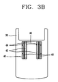
- Fig. 3B is a frontal view illustrating a first body of the portable terminal according to one embodiment of the invention.
- Fig. 4 is a partial section view illustrating the first body and the second body of the portable terminal according to one embodiment of the invention.
- Fig. 5 is an enlargement section view of 'A' part of Fig. 2 in accordance with one embodiment.
- Fig. 6A and Fig. 6B are operational state views of the portable terminal according to one embodiment of the invention.
- Fig. 7 is a disassembled perspective view illustrating a portable terminal according to an embodiment of the invention.
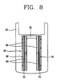
- Fig. 8 is a frontal view showing a second body of the portable terminal according to an embodiment of the invention.
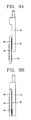
- Fig. 9A and Fig. 9B are operational state views of the portable terminal according to an embodiment of the invention.
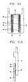
- Fig. 10 is a frontal view illustrating a second body of a portable terminal according to an embodiment of the invention.
- Fig. 11A, Fig. 11B, and Fig. 11C are operational state views of the portable terminal according to an embodiment of the invention.
- the present invention relates to a system and method for a portable terminal.
- the invention relates to a first body removably attached to a second body, and a magnetic mechanism for adjusting a relative position of the first body to the second body.
- the present invention provides a movable magnet installed at the first body and the fixed magnet is installed at the second body.
- a magnetic attraction between the magnets provides the convenience of automatically or substantially automatically opening or closing the first body from the second body of the terminal based on a user input.
- the present invention provides a magnetic driving force for placing the first body in an open or close position allowing repeatable, precision operation even after multiple usages.
- the present invention reduces the component count and overall terminal size because the magnets may be thin to produce a dimensionally reduced size portable terminal.
- the mobile terminal comprises a second body 10 to which an LCD 6 for displaying information is attached.
- the second body 10 in this example, has a printed circuit board (PCB) for mounting circuit components.
- a first body 20 slidably mounts to the upper surface of the second body 10 along a slide direction.
- a menu button 22 and a dial button 24 are disposed on the first body 20.
- a first open and close unit 30 and a second open and close unit 40 are disposed between the first body 20 and the second body 10.
- the first open and close unit or first slide unit 30 and the second open and close unit or second slide unit 40 provides guides for the first body 20 to be slidably moved along the second body 10 and forces by which the first body 20 automatically or substantially automatically moves.
- the first slide unit 30 comprises a first frame 34, a first magnet 32, and guide rails 38.
- the first frame 34 mounts on the upper surface of the second body 10.
- the first frame 34 provides a plurality of coupling holes 36 for coupling to the upper surface of the second body 10.
- the first magnet 32 which in this example is a fixed magnet, mounts on the first frame 34 in a slide direction.
- the first magnet 32 may comprise two or more magnets.
- the guide rails 38 protrude by a chosen width, for example, along sides of the first frame 34 in a slide direction of the first body 20.
- the guide rails 38 may be replaced by a glide mechanism.
- the glide mechanism in one example, is one guide rail or, yet in another example, multiple guide rails.
- the second slide unit 40 mounts at the lower surface of the first body 20.
- the second slide unit 40 comprises a second frame 46 mounted at the lower surface of the first body 20.
- the second frame 46 has guide grooves 48 slidably adapted to mate with the guide rails 38.
- a second magnet 42 in this example a movable magnet, is mounted along the second frame 46 in a slide direction.
- the second magnet 42 is positioned having an opposing polarity to that of the first magnet 32 (see Fig. 3A).
- a plurality of coupling holes 44 are formed at both lateral surfaces of the second frame 46 for coupling to the first body 20.
- the guide rails 38 fits into the guide grooves 48 for slidably moving the first body 20.
- the first magnet 32 and the second magnet 42 produce a magnetic driving force in a direction in which the first body 20 is open.
- a second magnet 42 in this example a movable magnet, attaches to the sides of the second slide unit 40.
- Assembly of the mobile or portable terminal comprises the first frame 34 being bolted or coupled to the upper surface of the second body 10. Similar to the first frame 34 attachment to the mobile terminal, the second frame 46 is bolted or coupled to the first body 20.
- the guide rails 38 formed along the first frame 34 are fitted into the guide grooves 48 completing the assembly between the first body 20 and the second body 10.
- a locking unit 51 locks the first body 20 to the second body unit 10.
- the locking unit 51 limits a slide motion of the first body 20 along the second body 10 in a closed position.
- the locking unit 51 comprises a push button 52, a locking hook 54, a locking groove 58, and a spring 56.
- the push button 52 is inserted into an insertion groove 50 formed at one side of the second body 10.
- the insertion groove has one side accessible for a user to press.
- the locking hook 54 in this example, is integrally formed at the push button 52.
- the spring 56 is installed between another side of the push button 52 and the second body 10. The spring 56 provides an elastic force to the push button 52.
- the locking groove 58 is integrally formed on the upper side of the first body 20 and adapted to mate with the locking hook 54.
- the locking hook 54 attaches to the locking groove 58 formed at the first body 20.
- a user presses the push button 52 the locking hook 54 detaches from the locking groove 58.
- the first body 20 is released from the second body 10.
- a user presses a push button 52 to open the first body 20 to use the portable terminal.
- the locking hook 54 is detached from the locking groove 58 formed at the second body 10 to release the locking of the first body 20.
- a magnetic force produces an attractive force between the first magnet 32 and the second magnet 42. The attractive force provides a driving force by which the first body 20 opens, thereby assisting a user, automatically, or substantially automatically placing the first body 20 in an open position.
- first body 20 If the first body is closed, an upper end of the first magnet 32 and a lower end of the second magnet 42 overlap, thereby coupling to with each other, over a desired width.
- An attractive force generated between the magnets 32 and 42 is applied along a direction that the first body 20 is open.
- the first body 20 Upon releasing the first body 20 from a locked position, the first body 20 opens automatically or substantially automatically.
- the second magnet 42 and the first magnet 32 are positioned face to face.
- a user pushes the first body 20 toward the second body 10.
- the locking groove 58 attaches and locks to the locking hook 54.
- a first slide unit 30 mounts on an upper surface of the second body 10.
- the first magnet 32 in this example a fixed magnet, attaches to the first slide unit 30.
- the first slide unit 30 is as illustrated and described above in FIG. 3A.
- the first slide unit 30 comprises a first frame 34 mounted at the upper surface of the second body 10.
- the first frame 34 has a plurality of coupling holes 36 for bolting or screwing to the second body 10.
- a first magnet 32 in this example a fixed magnet, mounts to the first frame 34 along a slide direction.
- a guide rails 38 protrudes with a certain width at both sides of the first frame 34 along a slide direction.
- a second slide unit 60 mounts at a lower surface of the first body 20.
- a first movable magnet 64 and a second movable magnet 66 attach to the second slide unit 60.
- the first movable magnet 64 and the second magnet 66 couple with the first magnet 32.
- the second slide unit 60 comprises a second frame 62 mounted on a lower surface of the first body 20.
- a first movable magnet 64 is mounted, in this example as a pair of magnets, along the sides of the second frame 62 along a slide direction.
- the first movable magnet 64 is positioned to have an opposite polarity of that of the first magnet 32.
- the second movable magnet 66 is also constructed as a pair mounted at both sides of the second frame 62, and is positioned in-line with the first movable magnet 64.
- a magnetic force is generated between the first magnet 32 and the first movable magnet 64. The magnetic force provides a driving force in a direction of positioning the first body 20 in a closed position.
- a second movable magnet 66 mounts to a lower surface of the first body 20.
- the second movable magnet 66 is positioned in an opposite polarity to the first magnet 32.
- the second movable magnet 66 generates a magnetic force between the fixed magnet 32 to provide a magnetic driving force for moving the first body 20 to an open position.
- the second frame 62 is positioned at a lower surface of the first body 20 along a slide direction.
- the second frame comprises a plurality of coupling holes 68 at both lateral surfaces.
- the second frame 62 is bolted or coupled though the plurality of coupling holes along a slide direction to the first body 20.
- the guide rails 38 of the first body 10 are inserted into and glide within a guide groove 70 in the second frame 62 for guiding of the first body 20.
- a user pushes the first body 20 along a direction of an open position for using the portable terminal.
- the first movable magnet 64 is moved to an overlapping position with the first magnet 32.
- a magnetic force producing an attractive force is generated between the first movable magnet 64 and the first magnet 32.
- the attractive force provides a magnetic driving force to place the first body 20 in an open position.
- the magnetic driving force positions the first body in an open position.
- a user pushes the first body 20 along a direction of a closed position.
- the fixed magnet 32 is moved from the first movable magnet 64 to an overlapping position with the second movable magnet 66.
- An attractive force is generated between the fixed magnet 32 and the second movable magnet 66 providing a driving force to place the first body 20 in a closed position.
- the magnetic driving force automatically closes the first body 20.
- the sliding unit produces a free stop type portable terminal capable of stopping the first body 20 at a user's desired position.
- a plurality of magnets are positioned along a lower surface of the first body 20.
- the sliding unit comprises the first magnet 32 attached to a first frame 34 mounted on an upper surface of the second body 10 along a slide direction.
- Movable magnets 82, 84, and 86 are attached at a user chosen interval to a second frame 80 mounted along a lower surface of the first body 20 of a slide direction.
- Three movable magnets in one example, comprise a first movable magnet 82 arranged at a lower side of the first body 20 in a slide direction for generating a magnetic force between the first magnet 32.
- the magnetic force provides a driving force to the first body 20 when the first body 20 is open.
- a second movable magnet 84 positioned in the middle of the first body 20 generates a magnetic force between the first magnet 32.
- the magnetic force provides a driving force to place the first body 20 when in a middle position in an open position.
- a third movable magnet 86 located on the upper side of the first body 20 provides a driving force when the first body is closed.
- a magnetic force is generated between the first magnet 32 and the second movable magnet 84.
- the first body 20 is automatically in an open position in the middle position.
- a magnetic force is generated between the first magnet 32 and the first movable magnet 82.
- the first body 20 is placed in a maximum open position.
- a user pushes the first body 20 toward a closed position after using the portable terminal.
- a magnetic force is generated between the first magnet 32 and the third movable magnet 86. The magnetic force causes the first body 20 to automatically close.
- the present invention is described in the context of a mobile terminal, the present invention may also be used in any wired or wireless communication systems using mobile devices, such as PDAs and laptop computers equipped with wired and wireless communication capabilities. Moreover, the use of certain terms to describe the present invention should not limit the scope of the present invention to certain type of wireless communication system, such as UMTS. The present invention is also applicable to other wireless communication systems using different air interfaces and/or physical layers, for example, TDMA, CDMA, FDMA, WCDMA, etc.
- the preferred embodiments may be implemented as a method, system or article of manufacture using standard programming and/or engineering techniques to produce software, firmware, hardware, or any combination thereof.
- article of manufacture refers to code or logic implemented in hardware logic (e.g., an integrated circuit chip, Field Programmable Gate Array (FPGA), Application Specific Integrated Circuit (ASIC), etc.) or a computer readable medium (e.g., magnetic storage medium (e.g., hard disk drives, floppy disks, tape, etc.), optical storage (CD-ROMs, optical disks, etc.), volatile and non-volatile memory devices (e.g., EEPROMs, ROMs, PROMs, RAMs, DRAMs, SRAMs, firmware, programmable logic, etc.).
- FPGA Field Programmable Gate Array
- ASIC Application Specific Integrated Circuit
- Code in the computer readable medium is accessed and executed by a processor.
- the code in which preferred embodiments are implemented may further be accessible through a transmission media or from a file server over a network.
- the article of manufacture in which the code is implemented may comprise a transmission media, such as a network transmission line, wireless transmission media, signals propagating through space, radio waves, infrared signals, etc.
- a transmission media such as a network transmission line, wireless transmission media, signals propagating through space, radio waves, infrared signals, etc.
Landscapes
- Engineering & Computer Science (AREA)
- Signal Processing (AREA)
- Computer Networks & Wireless Communication (AREA)
- Telephone Set Structure (AREA)
- Structure Of Receivers (AREA)
- Casings For Electric Apparatus (AREA)
- Input Circuits Of Receivers And Coupling Of Receivers And Audio Equipment (AREA)
Applications Claiming Priority (2)
| Application Number | Priority Date | Filing Date | Title |
|---|---|---|---|
| KR2003094283 | 2003-12-20 | ||
| KR1020030094283A KR100724400B1 (ko) | 2003-12-20 | 2003-12-20 | 자석을 이용한 휴대용 단말기의 슬라이드 개폐장치 |
Publications (2)
| Publication Number | Publication Date |
|---|---|
| EP1545099A1 true EP1545099A1 (fr) | 2005-06-22 |
| EP1545099B1 EP1545099B1 (fr) | 2010-12-08 |
Family
ID=34511260
Family Applications (1)
| Application Number | Title | Priority Date | Filing Date |
|---|---|---|---|
| EP04030146A Expired - Lifetime EP1545099B1 (fr) | 2003-12-20 | 2004-12-20 | Procédé et dispositif pour un terminal de communication radio portable de type coulissant |
Country Status (6)
| Country | Link |
|---|---|
| US (1) | US7269451B2 (fr) |
| EP (1) | EP1545099B1 (fr) |
| KR (1) | KR100724400B1 (fr) |
| CN (2) | CN1655467A (fr) |
| AT (1) | ATE491301T1 (fr) |
| DE (1) | DE602004030415D1 (fr) |
Cited By (5)
| Publication number | Priority date | Publication date | Assignee | Title |
|---|---|---|---|---|
| JP2007288436A (ja) * | 2006-04-14 | 2007-11-01 | Matsushita Electric Ind Co Ltd | スライド型携帯端末 |
| EP1858234A2 (fr) | 2006-05-16 | 2007-11-21 | Nokia Corporation | Mécanisme coulissant d'un dispositif électronique avec éléments magnétiques pour arranger le mécanisme dans une position déterminée |
| EP1898603A1 (fr) * | 2006-09-07 | 2008-03-12 | Samsung Electronics Co., Ltd. | Terminal portable de type coulissant |
| EP1926292A1 (fr) * | 2006-11-22 | 2008-05-28 | Samsung Techwin Co., Ltd | Structure de glissement de lévitation magnétique |
| EP1926289A3 (fr) * | 2006-11-27 | 2011-04-27 | LG Electronics Inc. | Dispositif électronique portable |
Families Citing this family (20)
| Publication number | Priority date | Publication date | Assignee | Title |
|---|---|---|---|---|
| KR100531880B1 (ko) * | 2003-07-10 | 2005-11-29 | 엘지전자 주식회사 | 슬라이드형 휴대용 단말기의 개폐 장치 |
| KR100617865B1 (ko) * | 2004-03-05 | 2006-08-28 | 주식회사 팬택앤큐리텔 | 자기부상식 이동통신단말기 |
| EP1829338B1 (fr) * | 2004-12-20 | 2008-12-03 | Nokia Corporation | Dispositif electronique |
| US7899504B2 (en) * | 2004-12-29 | 2011-03-01 | Nokia Corporation | Mobile communication unit with display area widening mechanism |
| KR20060081959A (ko) * | 2005-01-11 | 2006-07-14 | 피닉스코리아 주식회사 | 서로 회전하거나 슬라이드 이동하는 두 유닛을 구비하는휴대장치 및 그 휴대장치에 사용되는 결합장치 |
| KR100747571B1 (ko) * | 2005-11-07 | 2007-08-08 | 엘지전자 주식회사 | 반자동 슬라이드 모듈 및 이를 구비한 슬라이드 폰 |
| TWM295704U (en) * | 2006-01-06 | 2006-08-11 | Jarllytec Co Ltd | Alignment mechanism for sliding track |
| KR100713499B1 (ko) * | 2006-04-12 | 2007-05-02 | 삼성전자주식회사 | 슬라이딩 모듈을 구비한 휴대용 단말기 |
| KR100722836B1 (ko) * | 2006-04-14 | 2007-05-30 | (주)하이텍파츠 | 전자력을 이용한 슬라이딩 구동수단을 구비한 휴대용전자장치 |
| KR100781165B1 (ko) * | 2006-09-08 | 2007-11-30 | 삼성테크윈 주식회사 | 휴대용 전자기기용 슬라이딩 구조체 |
| KR100833946B1 (ko) * | 2006-12-20 | 2008-05-30 | 삼성테크윈 주식회사 | 전자기기용 슬라이딩 구조체 |
| US7831286B2 (en) * | 2006-12-26 | 2010-11-09 | Samsung Techwin Co., Ltd. | Sliding structure for electronic device |
| KR101181385B1 (ko) * | 2007-01-18 | 2012-09-20 | 삼성테크윈 주식회사 | 자기부상 슬라이딩 구조체 |
| TWI333774B (en) | 2007-02-05 | 2010-11-21 | Asustek Comp Inc | Slidable cell phone |
| JP2009003614A (ja) * | 2007-06-20 | 2009-01-08 | Sony Corp | スライド機構及び電子機器 |
| TW200907188A (en) * | 2007-08-02 | 2009-02-16 | Benq Corp | Sliding mechanism and method thereof and electronic device using the same |
| CN101453853B (zh) * | 2007-12-07 | 2012-03-14 | 鸿富锦精密工业(深圳)有限公司 | 滑动机构 |
| CN101657077B (zh) | 2008-08-22 | 2013-06-05 | 深圳富泰宏精密工业有限公司 | 电子装置 |
| US9898048B2 (en) * | 2016-01-20 | 2018-02-20 | Nanoport Technology Inc. | Interconnectable electronic device with magnetic rail |
| CN108769324B (zh) * | 2018-07-27 | 2021-04-27 | 北京小米移动软件有限公司 | 滑轨及移动终端 |
Citations (5)
| Publication number | Priority date | Publication date | Assignee | Title |
|---|---|---|---|---|
| WO1999043135A1 (fr) | 1998-02-20 | 1999-08-26 | Koninklijke Philips Electronics N.V. | Telephone portatif a unite microphone mobile |
| US20010009847A1 (en) | 2000-01-24 | 2001-07-26 | Lg Electronics Inc. | Drawer-type mobile phone |
| KR20020014431A (ko) | 2000-08-18 | 2002-02-25 | 윤종용 | 길이방향으로 신장가능한 셀룰러 폰 |
| KR20030027212A (ko) | 2001-09-14 | 2003-04-07 | 삼성전자주식회사 | 자성을 이용한 휴대용 단말기의 힌지 장치 |
| EP1496674A2 (fr) | 2003-07-11 | 2005-01-12 | Lg Electronics Inc. | Terminal portable du type coulissant |
Family Cites Families (9)
| Publication number | Priority date | Publication date | Assignee | Title |
|---|---|---|---|---|
| KR0163257B1 (ko) | 1995-07-18 | 1998-12-01 | 마종남 | 개선된 송수화기를 갖는 휴대용 무선전화기 |
| KR20000014986A (ko) * | 1998-08-26 | 2000-03-15 | 윤종용 | 플립형 무선 단말기의 커버 개폐장치 |
| CN2419752Y (zh) * | 2000-01-19 | 2001-02-14 | 许明德 | 手机自动翻盖机构 |
| JP3642261B2 (ja) * | 2000-05-16 | 2005-04-27 | 日本電気株式会社 | 無線端末 |
| CN1371035A (zh) * | 2001-02-20 | 2002-09-25 | 宏碁股份有限公司 | 便携电脑装置的磁性开关装置 |
| FI20010894A7 (fi) * | 2001-04-27 | 2002-10-28 | Nokia Corp | Kaksiosainen laite |
| JP2003348204A (ja) * | 2002-05-27 | 2003-12-05 | Matsushita Electric Ind Co Ltd | 移動体通信端末装置 |
| KR100484732B1 (ko) * | 2002-11-19 | 2005-04-22 | 삼성전자주식회사 | 슬라이딩 타입 휴대용 무선 단말기 |
| US20050079902A1 (en) * | 2003-10-08 | 2005-04-14 | Wei-Chih Chen | Positioning apparatus and method for a slide cover |
-
2003
- 2003-12-20 KR KR1020030094283A patent/KR100724400B1/ko not_active Expired - Fee Related
-
2004
- 2004-12-20 CN CNA2004100758909A patent/CN1655467A/zh active Pending
- 2004-12-20 EP EP04030146A patent/EP1545099B1/fr not_active Expired - Lifetime
- 2004-12-20 CN CN201210376187.6A patent/CN102883008B/zh not_active Expired - Fee Related
- 2004-12-20 DE DE602004030415T patent/DE602004030415D1/de not_active Expired - Lifetime
- 2004-12-20 AT AT04030146T patent/ATE491301T1/de not_active IP Right Cessation
- 2004-12-20 US US11/019,813 patent/US7269451B2/en not_active Expired - Fee Related
Patent Citations (5)
| Publication number | Priority date | Publication date | Assignee | Title |
|---|---|---|---|---|
| WO1999043135A1 (fr) | 1998-02-20 | 1999-08-26 | Koninklijke Philips Electronics N.V. | Telephone portatif a unite microphone mobile |
| US20010009847A1 (en) | 2000-01-24 | 2001-07-26 | Lg Electronics Inc. | Drawer-type mobile phone |
| KR20020014431A (ko) | 2000-08-18 | 2002-02-25 | 윤종용 | 길이방향으로 신장가능한 셀룰러 폰 |
| KR20030027212A (ko) | 2001-09-14 | 2003-04-07 | 삼성전자주식회사 | 자성을 이용한 휴대용 단말기의 힌지 장치 |
| EP1496674A2 (fr) | 2003-07-11 | 2005-01-12 | Lg Electronics Inc. | Terminal portable du type coulissant |
Cited By (11)
| Publication number | Priority date | Publication date | Assignee | Title |
|---|---|---|---|---|
| JP2007288436A (ja) * | 2006-04-14 | 2007-11-01 | Matsushita Electric Ind Co Ltd | スライド型携帯端末 |
| EP1858234A2 (fr) | 2006-05-16 | 2007-11-21 | Nokia Corporation | Mécanisme coulissant d'un dispositif électronique avec éléments magnétiques pour arranger le mécanisme dans une position déterminée |
| EP1858234A3 (fr) * | 2006-05-16 | 2009-06-17 | Nokia Corporation | Mécanisme coulissant d'un dispositif électronique avec éléments magnétiques pour arranger le mécanisme dans une position déterminée |
| US7647081B2 (en) | 2006-05-16 | 2010-01-12 | Nokia Corporation | Electronic device sliding mechanism |
| EP1898603A1 (fr) * | 2006-09-07 | 2008-03-12 | Samsung Electronics Co., Ltd. | Terminal portable de type coulissant |
| CN101141500B (zh) * | 2006-09-07 | 2011-03-09 | 三星电子株式会社 | 滑动式便携终端 |
| US8046034B2 (en) | 2006-09-07 | 2011-10-25 | Samsung Electronics Co., Ltd | Sliding-type portable terminal |
| EP1926292A1 (fr) * | 2006-11-22 | 2008-05-28 | Samsung Techwin Co., Ltd | Structure de glissement de lévitation magnétique |
| US7907980B2 (en) | 2006-11-22 | 2011-03-15 | Samsung Techwin Co., Ltd. | Magnetic levitation sliding structure |
| EP1926289A3 (fr) * | 2006-11-27 | 2011-04-27 | LG Electronics Inc. | Dispositif électronique portable |
| US8219160B2 (en) | 2006-11-27 | 2012-07-10 | Lg Electronics Inc. | Portable electronic device |
Also Published As
| Publication number | Publication date |
|---|---|
| CN102883008A (zh) | 2013-01-16 |
| KR100724400B1 (ko) | 2007-06-04 |
| US20050136698A1 (en) | 2005-06-23 |
| ATE491301T1 (de) | 2010-12-15 |
| CN1655467A (zh) | 2005-08-17 |
| EP1545099B1 (fr) | 2010-12-08 |
| US7269451B2 (en) | 2007-09-11 |
| KR20050062263A (ko) | 2005-06-23 |
| DE602004030415D1 (de) | 2011-01-20 |
| CN102883008B (zh) | 2016-08-17 |
Similar Documents
| Publication | Publication Date | Title |
|---|---|---|
| US7269451B2 (en) | Method and system for a slide type portable terminal | |
| US8029309B2 (en) | Electronic devices with sliding and tilting mechanisms, and associated methods | |
| CN215986657U (zh) | 光学元件驱动机构 | |
| US8913396B2 (en) | Card holding mechanism and electronic device | |
| US7337450B2 (en) | Electronic apparatus | |
| US20100166414A1 (en) | Lens cover and portable electronic device using the same | |
| US20100046149A1 (en) | Sliding electronic device | |
| KR102243690B1 (ko) | 이동 단말기 | |
| EP1871076A1 (fr) | Module coulissant pour téléphone mobile | |
| US20080005867A1 (en) | Sliding mechanism for slide-type portable electronic device | |
| EP2509287B1 (fr) | Mécanisme de coulissement-inclinaison | |
| CN115220165A (zh) | 驱动机构 | |
| US20210200261A1 (en) | Display device | |
| CN105051599B (zh) | 开闭装置 | |
| EP1916826B1 (fr) | Dispositifs électroniques équipés de méchanismes coulissants et pivotants | |
| US20070297267A1 (en) | Portable electronic device and coupling device for the same | |
| US6159632A (en) | Battery accommodating structure for electronic equipment | |
| JP2003233328A (ja) | 表示装置を具えた電子装置 | |
| CN110460693A (zh) | 电子设备 | |
| US8164890B2 (en) | Sliding and tilting mechanism and portable electronic device using the same | |
| EP2296354B1 (fr) | Dispositif électronique portable | |
| CN117823517A (zh) | 转轴装置及电子设备 | |
| KR102032856B1 (ko) | 풀 스크린 스마트폰용 카메라 슬라이드 개폐장치 | |
| CN208079143U (zh) | 移动终端 | |
| US8238083B2 (en) | Slide mechanism for slide-type portable electronic device |
Legal Events
| Date | Code | Title | Description |
|---|---|---|---|
| PUAI | Public reference made under article 153(3) epc to a published international application that has entered the european phase |
Free format text: ORIGINAL CODE: 0009012 |
|
| AK | Designated contracting states |
Kind code of ref document: A1 Designated state(s): AT BE BG CH CY CZ DE DK EE ES FI FR GB GR HU IE IS IT LI LT LU MC NL PL PT RO SE SI SK TR |
|
| AX | Request for extension of the european patent |
Extension state: AL BA HR LV MK YU |
|
| RIN1 | Information on inventor provided before grant (corrected) |
Inventor name: KWON, SOON-SUNG |
|
| 17P | Request for examination filed |
Effective date: 20051202 |
|
| AKX | Designation fees paid |
Designated state(s): AT BE BG CH CY CZ DE DK EE ES FI FR GB GR HU IE IS IT LI LT LU MC NL PL PT RO SE SI SK TR |
|
| 17Q | First examination report despatched |
Effective date: 20060112 |
|
| GRAP | Despatch of communication of intention to grant a patent |
Free format text: ORIGINAL CODE: EPIDOSNIGR1 |
|
| GRAC | Information related to communication of intention to grant a patent modified |
Free format text: ORIGINAL CODE: EPIDOSCIGR1 |
|
| GRAS | Grant fee paid |
Free format text: ORIGINAL CODE: EPIDOSNIGR3 |
|
| GRAA | (expected) grant |
Free format text: ORIGINAL CODE: 0009210 |
|
| RAP1 | Party data changed (applicant data changed or rights of an application transferred) |
Owner name: LG ELECTRONICS, INC. |
|
| AK | Designated contracting states |
Kind code of ref document: B1 Designated state(s): AT BE BG CH CY CZ DE DK EE ES FI FR GB GR HU IE IS IT LI LT LU MC NL PL PT RO SE SI SK TR |
|
| REG | Reference to a national code |
Ref country code: GB Ref legal event code: FG4D |
|
| REG | Reference to a national code |
Ref country code: CH Ref legal event code: EP |
|
| REG | Reference to a national code |
Ref country code: IE Ref legal event code: FG4D |
|
| REF | Corresponds to: |
Ref document number: 602004030415 Country of ref document: DE Date of ref document: 20110120 Kind code of ref document: P |
|
| REG | Reference to a national code |
Ref country code: NL Ref legal event code: VDEP Effective date: 20101208 |
|
| PG25 | Lapsed in a contracting state [announced via postgrant information from national office to epo] |
Ref country code: LT Free format text: LAPSE BECAUSE OF FAILURE TO SUBMIT A TRANSLATION OF THE DESCRIPTION OR TO PAY THE FEE WITHIN THE PRESCRIBED TIME-LIMIT Effective date: 20101208 |
|
| LTIE | Lt: invalidation of european patent or patent extension |
Effective date: 20101208 |
|
| PG25 | Lapsed in a contracting state [announced via postgrant information from national office to epo] |
Ref country code: CY Free format text: LAPSE BECAUSE OF FAILURE TO SUBMIT A TRANSLATION OF THE DESCRIPTION OR TO PAY THE FEE WITHIN THE PRESCRIBED TIME-LIMIT Effective date: 20101208 Ref country code: AT Free format text: LAPSE BECAUSE OF FAILURE TO SUBMIT A TRANSLATION OF THE DESCRIPTION OR TO PAY THE FEE WITHIN THE PRESCRIBED TIME-LIMIT Effective date: 20101208 Ref country code: FI Free format text: LAPSE BECAUSE OF FAILURE TO SUBMIT A TRANSLATION OF THE DESCRIPTION OR TO PAY THE FEE WITHIN THE PRESCRIBED TIME-LIMIT Effective date: 20101208 Ref country code: SE Free format text: LAPSE BECAUSE OF FAILURE TO SUBMIT A TRANSLATION OF THE DESCRIPTION OR TO PAY THE FEE WITHIN THE PRESCRIBED TIME-LIMIT Effective date: 20101208 Ref country code: NL Free format text: LAPSE BECAUSE OF FAILURE TO SUBMIT A TRANSLATION OF THE DESCRIPTION OR TO PAY THE FEE WITHIN THE PRESCRIBED TIME-LIMIT Effective date: 20101208 Ref country code: BG Free format text: LAPSE BECAUSE OF FAILURE TO SUBMIT A TRANSLATION OF THE DESCRIPTION OR TO PAY THE FEE WITHIN THE PRESCRIBED TIME-LIMIT Effective date: 20110308 Ref country code: SI Free format text: LAPSE BECAUSE OF FAILURE TO SUBMIT A TRANSLATION OF THE DESCRIPTION OR TO PAY THE FEE WITHIN THE PRESCRIBED TIME-LIMIT Effective date: 20101208 |
|
| PG25 | Lapsed in a contracting state [announced via postgrant information from national office to epo] |
Ref country code: CZ Free format text: LAPSE BECAUSE OF FAILURE TO SUBMIT A TRANSLATION OF THE DESCRIPTION OR TO PAY THE FEE WITHIN THE PRESCRIBED TIME-LIMIT Effective date: 20101208 Ref country code: IS Free format text: LAPSE BECAUSE OF FAILURE TO SUBMIT A TRANSLATION OF THE DESCRIPTION OR TO PAY THE FEE WITHIN THE PRESCRIBED TIME-LIMIT Effective date: 20110408 Ref country code: MC Free format text: LAPSE BECAUSE OF NON-PAYMENT OF DUE FEES Effective date: 20101231 Ref country code: GR Free format text: LAPSE BECAUSE OF FAILURE TO SUBMIT A TRANSLATION OF THE DESCRIPTION OR TO PAY THE FEE WITHIN THE PRESCRIBED TIME-LIMIT Effective date: 20110309 Ref country code: EE Free format text: LAPSE BECAUSE OF FAILURE TO SUBMIT A TRANSLATION OF THE DESCRIPTION OR TO PAY THE FEE WITHIN THE PRESCRIBED TIME-LIMIT Effective date: 20101208 Ref country code: ES Free format text: LAPSE BECAUSE OF FAILURE TO SUBMIT A TRANSLATION OF THE DESCRIPTION OR TO PAY THE FEE WITHIN THE PRESCRIBED TIME-LIMIT Effective date: 20110319 Ref country code: PT Free format text: LAPSE BECAUSE OF FAILURE TO SUBMIT A TRANSLATION OF THE DESCRIPTION OR TO PAY THE FEE WITHIN THE PRESCRIBED TIME-LIMIT Effective date: 20110408 Ref country code: BE Free format text: LAPSE BECAUSE OF FAILURE TO SUBMIT A TRANSLATION OF THE DESCRIPTION OR TO PAY THE FEE WITHIN THE PRESCRIBED TIME-LIMIT Effective date: 20101208 |
|
| REG | Reference to a national code |
Ref country code: CH Ref legal event code: PL |
|
| PG25 | Lapsed in a contracting state [announced via postgrant information from national office to epo] |
Ref country code: RO Free format text: LAPSE BECAUSE OF FAILURE TO SUBMIT A TRANSLATION OF THE DESCRIPTION OR TO PAY THE FEE WITHIN THE PRESCRIBED TIME-LIMIT Effective date: 20101208 Ref country code: SK Free format text: LAPSE BECAUSE OF FAILURE TO SUBMIT A TRANSLATION OF THE DESCRIPTION OR TO PAY THE FEE WITHIN THE PRESCRIBED TIME-LIMIT Effective date: 20101208 Ref country code: PL Free format text: LAPSE BECAUSE OF FAILURE TO SUBMIT A TRANSLATION OF THE DESCRIPTION OR TO PAY THE FEE WITHIN THE PRESCRIBED TIME-LIMIT Effective date: 20101208 |
|
| PLBE | No opposition filed within time limit |
Free format text: ORIGINAL CODE: 0009261 |
|
| STAA | Information on the status of an ep patent application or granted ep patent |
Free format text: STATUS: NO OPPOSITION FILED WITHIN TIME LIMIT |
|
| PG25 | Lapsed in a contracting state [announced via postgrant information from national office to epo] |
Ref country code: IE Free format text: LAPSE BECAUSE OF NON-PAYMENT OF DUE FEES Effective date: 20101220 Ref country code: LI Free format text: LAPSE BECAUSE OF NON-PAYMENT OF DUE FEES Effective date: 20101231 Ref country code: CH Free format text: LAPSE BECAUSE OF NON-PAYMENT OF DUE FEES Effective date: 20101231 Ref country code: DK Free format text: LAPSE BECAUSE OF FAILURE TO SUBMIT A TRANSLATION OF THE DESCRIPTION OR TO PAY THE FEE WITHIN THE PRESCRIBED TIME-LIMIT Effective date: 20101208 |
|
| 26N | No opposition filed |
Effective date: 20110909 |
|
| PG25 | Lapsed in a contracting state [announced via postgrant information from national office to epo] |
Ref country code: IT Free format text: LAPSE BECAUSE OF FAILURE TO SUBMIT A TRANSLATION OF THE DESCRIPTION OR TO PAY THE FEE WITHIN THE PRESCRIBED TIME-LIMIT Effective date: 20101208 |
|
| REG | Reference to a national code |
Ref country code: DE Ref legal event code: R097 Ref document number: 602004030415 Country of ref document: DE Effective date: 20110909 |
|
| PG25 | Lapsed in a contracting state [announced via postgrant information from national office to epo] |
Ref country code: HU Free format text: LAPSE BECAUSE OF FAILURE TO SUBMIT A TRANSLATION OF THE DESCRIPTION OR TO PAY THE FEE WITHIN THE PRESCRIBED TIME-LIMIT Effective date: 20110609 Ref country code: LU Free format text: LAPSE BECAUSE OF NON-PAYMENT OF DUE FEES Effective date: 20101220 |
|
| PG25 | Lapsed in a contracting state [announced via postgrant information from national office to epo] |
Ref country code: TR Free format text: LAPSE BECAUSE OF FAILURE TO SUBMIT A TRANSLATION OF THE DESCRIPTION OR TO PAY THE FEE WITHIN THE PRESCRIBED TIME-LIMIT Effective date: 20101208 |
|
| REG | Reference to a national code |
Ref country code: FR Ref legal event code: PLFP Year of fee payment: 12 |
|
| REG | Reference to a national code |
Ref country code: FR Ref legal event code: PLFP Year of fee payment: 13 |
|
| PGFP | Annual fee paid to national office [announced via postgrant information from national office to epo] |
Ref country code: DE Payment date: 20161107 Year of fee payment: 13 Ref country code: FR Payment date: 20161114 Year of fee payment: 13 Ref country code: GB Payment date: 20161110 Year of fee payment: 13 |
|
| REG | Reference to a national code |
Ref country code: DE Ref legal event code: R119 Ref document number: 602004030415 Country of ref document: DE |
|
| GBPC | Gb: european patent ceased through non-payment of renewal fee |
Effective date: 20171220 |
|
| REG | Reference to a national code |
Ref country code: FR Ref legal event code: ST Effective date: 20180831 |
|
| PG25 | Lapsed in a contracting state [announced via postgrant information from national office to epo] |
Ref country code: FR Free format text: LAPSE BECAUSE OF NON-PAYMENT OF DUE FEES Effective date: 20180102 Ref country code: DE Free format text: LAPSE BECAUSE OF NON-PAYMENT OF DUE FEES Effective date: 20180703 |
|
| PG25 | Lapsed in a contracting state [announced via postgrant information from national office to epo] |
Ref country code: GB Free format text: LAPSE BECAUSE OF NON-PAYMENT OF DUE FEES Effective date: 20171220 |