EP1545100B1 - Terminal de communication comportant une face avant personnalisable - Google Patents
Terminal de communication comportant une face avant personnalisable Download PDFInfo
- Publication number
- EP1545100B1 EP1545100B1 EP04300888A EP04300888A EP1545100B1 EP 1545100 B1 EP1545100 B1 EP 1545100B1 EP 04300888 A EP04300888 A EP 04300888A EP 04300888 A EP04300888 A EP 04300888A EP 1545100 B1 EP1545100 B1 EP 1545100B1
- Authority
- EP
- European Patent Office
- Prior art keywords
- electronic device
- keypad module
- printed circuit
- keyboard
- terminal
- Prior art date
- Legal status (The legal status is an assumption and is not a legal conclusion. Google has not performed a legal analysis and makes no representation as to the accuracy of the status listed.)
- Expired - Lifetime
Links
- 239000013013 elastic material Substances 0.000 claims description 2
- 238000004519 manufacturing process Methods 0.000 description 2
- 239000002184 metal Substances 0.000 description 2
- 230000001413 cellular effect Effects 0.000 description 1
- 239000003086 colorant Substances 0.000 description 1
- 239000000428 dust Substances 0.000 description 1
- 238000012423 maintenance Methods 0.000 description 1
- 230000007257 malfunction Effects 0.000 description 1
- 239000004033 plastic Substances 0.000 description 1
- 239000002985 plastic film Substances 0.000 description 1
- 229920006255 plastic film Polymers 0.000 description 1
Images


Classifications
-
- H—ELECTRICITY
- H04—ELECTRIC COMMUNICATION TECHNIQUE
- H04M—TELEPHONIC COMMUNICATION
- H04M1/00—Substation equipment, e.g. for use by subscribers
- H04M1/02—Constructional features of telephone sets
- H04M1/0202—Portable telephone sets, e.g. cordless phones, mobile phones or bar type handsets
- H04M1/0279—Improving the user comfort or ergonomics
-
- H—ELECTRICITY
- H04—ELECTRIC COMMUNICATION TECHNIQUE
- H04M—TELEPHONIC COMMUNICATION
- H04M1/00—Substation equipment, e.g. for use by subscribers
- H04M1/02—Constructional features of telephone sets
- H04M1/0202—Portable telephone sets, e.g. cordless phones, mobile phones or bar type handsets
- H04M1/0279—Improving the user comfort or ergonomics
- H04M1/0283—Improving the user comfort or ergonomics for providing a decorative aspect, e.g. customization of casings, exchangeable faceplate
-
- H—ELECTRICITY
- H04—ELECTRIC COMMUNICATION TECHNIQUE
- H04M—TELEPHONIC COMMUNICATION
- H04M1/00—Substation equipment, e.g. for use by subscribers
- H04M1/02—Constructional features of telephone sets
- H04M1/23—Construction or mounting of dials or of equivalent devices; Means for facilitating the use thereof
Definitions
- the present invention relates to an electronic device with a customizable keyboard.
- Non-exclusive fields of application of the invention are mobile or fixed communication terminals or for example video game consoles.
- An electronic device of this type comprises a human-machine interface comprising, inter alia, a keyboard and a display screen.
- the keyboard and the display screen are generally located on the front face of the device.
- the keyboard and the display screen are connected directly to a circuit board located below.
- One of the key elements of customization is the keyboard. It is therefore particularly interesting to allow the user to change the keyboard as easily as possible.
- the keyboard of a terminal is generally secured to the front of the terminal.
- the key layer must remain identical from one front face to another for the same terminal.
- the printed circuit being wired to receive keys with a given layout, can not establish connections with a keyboard whose keys would have another arrangement.
- the document WO 02 37907 offers a removable computer keyboard.
- the keyboard includes an integrated connection socket grouping all connections with the keys on the keyboard.
- the integrated connection socket of the keyboard connects to a connection socket located on the body of the computer.
- the user can use another keyboard with Arabic type characters.
- Attaching the keyboard does not allow the computer to be used in other positions than on a horizontal plane without the risk of disconnecting the keyboard.
- the object of the invention is to present a solution to these problems and to produce an electronic device with a customizable keyboard whose security of attachment is increased.
- the invention for this purpose relates to an electronic device as defined in claim 1.
- the keyboard is securely locked on the electronic device and the latter can be used in any position, on the other hand, when the keyboard is detached from the electronic device, the printed circuit of the device is not exposed and will not be damaged.
- the keyboard module comprises a tab for the electrical connection of the keyboard module to the printed circuit of the electronic device itself having an electrical connector.
- the keyboard module comprises a specific printed circuit board, keys, the keys being connected to the specific printed circuit of the module.
- the keyboard module may comprise, inter alia, a specific printed circuit board, keys connected to the specific printed circuit board, a tab allowing the electrical connection of the keyboard module to the printed circuit board and the maintenance of the keyboard module on the front face of the electronic device.
- a communication terminal can be a cellular telephone type GSM, DCS (Digital Communication System in English) or UMTS (Universal Mobile Telecommunications System in English), or radio transceivers, such as, for example, a pager, or a personal digital assistant (PDA) or a telephone type DECI (Digital European Cordless Telecommunications).
- GSM Global System for Mobile Communications
- DCS Digital Communication System in English
- UMTS Universal Mobile Telecommunications System in English
- radio transceivers such as, for example, a pager, or a personal digital assistant (PDA) or a telephone type DECI (Digital European Cordless Telecommunications).
- PDA personal digital assistant
- DECI Digital European Cordless Telecommunications
- the figure 1 illustrates the terminal according to the invention in longitudinal section along the median axis of the terminal.
- the box of the terminal is composed of two faces: a front face 10 and a rear face 20.
- a display module 30 Under the front face 10 are a display module 30 and a keyboard module 40.
- This printed circuit 50 is substantially parallel to the front faces 10 and rear 20 of the terminal housing and extends over the entire inner surface of the terminal.
- the display module 30 is directly connected to the printed circuit board 50.
- the keyboard module 40 is connected to the printed circuit 50 via a connector 55 comprising connection points that are mapped to connection points located on the keyboard module 40, when the user of the terminal comes to apply the keyboard module 40 on the keyboard. terminal.
- keyboard module 40 The components of the keyboard module 40 and its features are described in detail in the following.
- a pin 60 exploded view on the figure 2 , having a substantially U-shaped with two lateral branches 61 ot 62 and a base 63, enchased the keyboard module 40 on its periphery to lock it to the terminal.
- the removable pin with its three sides, therefore enchased the keyboard module on three sides, which allows a very secure fixation of the keyboard.
- the user of the terminal wishes to remove the keyboard module 40
- the user unlocks the keyboard module 40 by first raising the pin 60.
- the pin 60 may for example comprise lugs 64 located near the free end of each branch 61 and 62 of the pin 60. These lugs allow to fix the pin 60 on the terminal. These lugs 64 are positioned in notches provided for this purpose on the terminal.
- the pin 60 may comprise branches 61 and 62 in a more elastic material than that of the base.
- the pin 60 when it does not bury the keyboard module 40, therefore comprises two convergent branches 61 and 62 situated in a common plane also at the base 63.
- the pin 60 enchased in force the keyboard module 40 on its periphery to lock the terminal by a spacing of the two branches 60 and 61.
- the pin 60 could also be substantially recessed rectangular shape. It would then have three sides taking the U-shape previously described but with in addition a small side, substantially parallel to the base 63, fixed at the end of the branches 61 and 62. In this embodiment, the detachable pin thus encases the keyboard module all around.
- the attachment of the keyboard on the mobile terminal is very safe and allows the use of the terminal in various positions without the risk of disconnection of the keyboard.
- the terminal has two parts: on the one hand, the keyboard module 40 and the pin 60 and, on the other hand, a functional core 70.
- the functional heart 70 of the terminal is composed, in particular, of the front face 10 of the box of the terminal, under which is the display module 30, the printed circuit 50, the battery 14, the antenna 12 and the rear face 20 of the terminal box comes close the back of the functional heart 70.
- the pin 60 comes to rest on a shoulder 41: practiced on the periphery of the keyboard module 40.
- the keyboard module 40 an exploded view of which is presented in figure 4 , has a substantially parallelepipedal shape comprising on one of its short sides a tab 42.
- the tab 42 could also be on one of the other side of the keyboard module 40, or anywhere on the back surface of the keyboard module 40, that is to say the face of the keyboard module 40 opposite the face supporting the keys.
- This tab 42 includes electrical connection points that are matched with electrical connection points of the connector 55 for electrical connection of the keyboard module 40 to the printed circuit board 50.
- the electrical connection between the keyboard module 40 and the printed circuit 50 of the terminal is thus performed via the tab 42 and not over the entire surface of the keyboard.
- the electrical connection between the keyboard module 40 and the printed circuit 50 of the terminal could, for example, also be carried out without the aid of the connector 55, directly on connection points located on the printed circuit 50.
- the tab 42 is also a means of holding the keyboard module 40 on the front face 10.
- the keyboard module 40 also comprises a layer of keys 43, possibly made of plastic, an elastomeric sheet 44, a plastic film 45 with metal cups 45a, a specific printed circuit board 46 of the keyboard 40 with light-emitting diodes and an insulating plate 47.
- the light emitting diodes allow the backlighting of the keyboard module 40 of the terminal. These light-emitting diodes are electrically connected to the specific printed circuit 46 of the keyboard 40.
- the key layer 43 via the metal cups 45a is electrically connected to the specific printed circuit 46 of the keyboard 40.
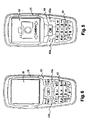
- the Figures 5 and 6 present two different types of keyboard modules 40 that can be connected on the same terminal.
- the keyboard module 40 of the figure 5 present 21 keys, that of the figure 6 has 23 keys, the keys 1, 2, and 3 have been swapped with the keys 7, 8, and 9 between the two keyboard modules 40.
- Some keys have different geometries between the two keyboard modules 40, for example the keys “hang up” And “stall” 43a and 43b.
- Some keys may also be backlit in a different way from one keyboard module 40 to another; in this case, the light-emitting diodes of the specific printed circuit 46 of the keyboard 40 have a different arrangement between the two keyboard modules 40.
- the diodes are permanently disposed during the manufacture of the terminal. If you fit a new keyboard with galvanized keys instead of being transparent then the diodes behind these galvanized keys continue to work and consume energy, although they are useless.
- keyboard module 40 of the invention comprising a specific printed circuit 46 with light emitting diodes, only the keys intended to be backlit have underlying light emitting diodes, or energy saving. And we always ensure the compatibility of all keyboard modules of different geometry with the user's terminal.
- terminals whose front and rear faces extend substantially parallel to each other in a single plane.
- the invention also applies to other types of terminals, such as, for example, terminals whose two front and rear faces (10, 20) consist of two parts. The two parts of each face are articulated around a hinge common to both sides allowing the terminal to bend on itself.
- the display module 30 under one of the two parts of the front face 10 is the display module 30 and under the other part of the front face 10 is the keyboard module 40 according to the invention.
- the terminal of the invention can be customized as much as possible at the end of the production line, or even by the user himself when buying the terminal.
- connection of the terminal can be tested without the keyboard module 40 since the connector 55 allows access.
- the pins can be used by the operator of the user's radio network to customize the terminal to his name.
Landscapes
- Engineering & Computer Science (AREA)
- Signal Processing (AREA)
- Telephone Set Structure (AREA)
- Input From Keyboards Or The Like (AREA)
- Telephone Function (AREA)
- Diaphragms For Electromechanical Transducers (AREA)
Description
- La présente invention concerne un dispositif électronique avec un clavier personnalisable.
- Des domaines d'application, non exclusifs, de l'invention sont les terminaux mobiles ou fixes de communication ou par exemple les consoles de jeux vidéo.
- Un dispositif électronique de ce type comprend une interface homme-machine comprenant, entre autres, un clavier et un écran d'affichage.
- Le clavier et l'écran d'affichage se trouvent généralement situés sur fa face avant du dispositif.
- Le clavier et l'écran d'affichage sont connectés directement sur un circuit imprimé situé dessous.
- De plus en plus d'utilisateurs de ce type de dispositifs, par exemple un terminal de communication, désirent personnaliser leur terminal.
- Un des éléments clef de la personnalisation est le clavier. Il s'avère donc particulièrement intéressant de permettre à l'utilisateur de changer de clavier le plus facilement possible.
- Le clavier d'un terminal est généralement solidaire de la face avant du terminal.
- Ainsi, pour changer de clavier, l'utilisateur doit changer toute la face avant du terminal et mettre ainsi à nu le circuit imprimé avant de venir emboîter une autre face avant et personnaliser son terminal.
- Ceci peut provoquer des dysfonctionnements liés à l'introduction de poussières sur le circuit imprimé.
- De plus, la nappe de touche doit rester identique d'une face avant à une autre pour le même terminal.
- En effet, si on met une face avant avec un clavier dont les touches ne sont pas disposées comme l'étaient les touches du clavier d'origine, alors il y aura une incompatibilité avec le circuit imprimé :
- Le circuit imprimé, étant câblé pour recevoir des touches avec une disposition donnée, ne peut pas établir des connexions avec un clavier dont les touches auraient une autre disposition.
- Le document
WO 02 37907 - Cependant, la fixation du clavier sur l'ordinateur est très peu sûre car elle consiste en un simple crochet et le clavier peut se déconnecter très facilement du corps de l'ordinateur.
- La fixation du clavier ne permet pas d'utiliser l'ordinateur dans d'autres positions que posé sur un plan horizontal sans risquer la déconnexion du clavier.
- Le document
US 2003/0211835 décrit un teléphone mobile muni d'un clavier interchangeable. - Dans le cas de l'application à un dispositif électronique de petite taille, par exemple un terminal mobile, et devant pouvoir être utilisé dans diverses positions notamment dans un plan vertical ou avec le clavier en regard du sol, le manque de sûreté dans la fixation du clavier sur le corps du dispositif peut devenir critique.
- L'invention a pour but de présenter une solution à ces problèmes et de réaliser un dispositif électronique avec un clavier personnalisable et dont la sûreté de la fixation est accrue.
- L'invention, à cet effet, concerne un dispositif électronique tel que défini dans la revendication 1.
- Ainsi, d'une part, le clavier est verrouillé de façon sûre sur le dispositif électronique et ce dernier peut être utilisé dans n'importe quelle position, d'autre part, lorsque le clavier est détaché du dispositif électronique, le circuit imprimé du dispositif n'est pas mis à nu et ne risque pas d'être détérioré.
- Dans un mode de réalisation de l'invention, le module clavier comprend une patte permettant la connexion électrique du module clavier sur le circuit imprimé du dispositif électronique disposant lui-même d'un connecteur électrique.
- Ainsi, différents claviers comprenant une disposition de touches différente peuvent être adaptés à un même dispositif.
- Dans un autre mode de réalisation de l'invention le module clavier comporte un circuit imprimé spécifique, des touches, les touches étant connectées au circuit imprimé spécifique du module
- Le module clavier peut comporter, entre autres, un circuit imprimé spécifique, des touches connectées au circuit imprimé spécifique, une patte permettant la connexion électrique du module clavier sur le circuit imprimé et le maintien du module clavier sur la face avant du dispositif électronique.
- D'autres caractéristiques et avantages de l'invention apparaîtront à la lecture de la description suivante d'un mode de réalisation particulier de l'invention dans lequel le dispositif est un terminal de communication, donné à titre illustratif et pas limitatif, et des dessins énoncés ci-dessous.
- La
figure 1 illustre le terminal selon l'invention en coupe longitudinale selon l'axe médian du terminal. - La
figure 2 illustre le terminal selon l'invention en vue éclatée. - La
figure 3 illustre le coeur fonctionnel du terminal selon l'invention en vue éclatée. - La
figure 4 illustre le module clavier du terminal selon l'invention en vue éclatée. - La
figure 5 illustre le terminal selon l'invention avec un premier exemple de clavier. - La
figure 6 illustre le terminal selon l'invention avec un deuxième exemple de clavier. - Dans la suite de la description, l'invention est décrite dans son application aux terminaux de communication.
- Elle s'applique plus généralement à tous types de dispositifs électroniques possédant une interface homme-machine comprenant un clavier.
- Un terminal de communication selon l'invention peut être un téléphone cellulaire de type GSM, DCS (Digital Communication System en anglais) ou UMTS (Universal Mobile Télécommunications System en anglais), ou les émetteurs-récepteurs radio, tels que, par exemple, un appareil de radiomessagerie, ou un assistant personnel numérique (personnal digital assistant ou PDA en anglais), ou encore un téléphone de type DECI (Digital European Cordless Telecommunications en anglais).
- La
figure 1 illustre le terminal selon l'invention en coupe longitudinale selon l'axe médian du terminal. - Le boitier du terminal est composé de deux faces : une face avant 10 et une face arrière 20.
- Sous la face arrière 20, à l'intérieur du boitier, se trouvent principalement l'antenne 12 et la batterie 14.
- Sous la face avant 10 se trouvent un module d'affichage 30 et un module clavier 40.
- Ces différents éléments du terminal sont connectés sur un circuit imprimé 50.
- Ce circuit imprimé 50 est sensiblement parallèle aux faces avant 10 et arrière 20 du boitier du terminal et s'étend sur toute la surface intérieure du terminal.
- Le module d'affichage 30 est directement connecté sur le circuit imprimé 50.
- Le module clavier 40 est connecté au circuit imprimé 50 via un connecteur 55 comprenant des points de connexions qui sont mis en correspondance avec des points de connexion situés sur le module clavier 40, lorsque l'utilisateur du terminal vient appliquer le module clavier 40 sur le terminal.
- Les composants du module clavier 40 et ses fonctionnalités sont décrits avec précision dans ce qui suit.
- Enfin une épingle 60, en vue éclatée sur la
figure 2 , présentant une forme sensiblement en U avec deux branches latérales 61 ot 62 et une base 63, vient enchâsser la module clavier 40 sur son pourtour afin de le verrouiller au terminal. Dans ce mode de réalisation, l'épingle amovible, avec ses trois côtés, vient donc enchâsser le module clavier sur trois côtés, ce qui permet une fixation très sûre du clavier. - Lorsque l'utilisateur du terminal désire enlever le module clavier 40, l'utilisateur déverrouille le module clavier 40 en levant au préalable l'épingle 60.
- L'épingle 60, en forme sensiblement en U, peut par exemple comprendre des ergots 64 situés prés de l'extrémité libre de chaque branche 61 et 62 de l'épingle 60. Ces ergots permettent de fixer l'épingle 60 sur le terminal. Ces ergots 64 viennent se positionner dans des encoches prévues à cet effet sur le terminal.
- Dans un autre mode de réalisation, l'épingle 60, en forme sensiblement en U, peut comprendre des branches 61 et 62 en un matériau plus élastique que celui de la base.
- L'épingle 60, lorsqu'elle n'enchâsse pas le module clavier 40, comprend donc deux branches 61 et 62 convergentes situées dans un plan commun également à la base 63.
- L'épingle 60 vient enchâsser en force le module clavier 40 sur son pourtour afin de le verrouiller au terminal par un écartement des deux branches 60 et 61.
- L'épingle 60 pourrait être également de forme sensiblement rectangulaire évidée. Elle aurait alors trois côtés reprenant la forme en U précédemment décrite mais avec en plus un petit côté, sensiblement parallèle à la base 63, fixé au bout des branches 61 et 62. Dans ce mode de réalisation, l'épingle amovible vient donc enchâsser le module clavier sur tout son pourtour.
- Ainsi, la fixation du clavier sur le terminal mobile est très sûre et permet d'utiliser le terminal dans diverses positions sans risquer la déconnexion du clavier.
- Le terminal présente deux parties : d'une part, le module clavier 40 et l'épingle 60 et, d'autre part, un coeur fonctionnel 70.
- Le coeur fonctionnel 70 du terminal, en vue éclatée sur la
figure 3 , est composé, notamment, de la face avant 10 du boitier du terminal, sous laquelle se trouve le module d'affichage 30, le circuit imprimé 50, la batterie 14, l'antenne 12 et la face arrière 20 du boitier du terminal vient clore l'arrière du coeur fonctionnel 70. - Lorsque l'utlisateur veut fixer le module clavier 40 sur le terminal, il vient poser le module clavier 40 sur l'emplacement 71 du coeur fonctionnel 70 réservé pour le module clavier 40 puis vient glisser l'épingle 60 autour du module clavier 40.
- L'épingle 60 vient s'appuyer sur un épaulement 41 : pratiqué sur le pourtour du module clavier 40.
- Le module clavier 40, dont une vue éclatée est présentée en
figure 4 , présente une forme sensiblement parallélipipédique comprenant sur l'un de ses petits côtés une patte 42. - La patte 42 pourrait également se trouver sur un des autres côté du module clavier 40, ou sur n'importe quel endroit de la surface arrière du module clavier 40, c'est à dire la face du module clavier 40 opposée à la face supportant les touches.
- Cette patte 42 comprend des points de connexions électriques qui sont mis en correspondance avec des points de connexion électrique du connecteur 55 permettant la connexion électrique du module clavier 40 au circuit imprimé 50.
- La connexion électrique entre le module clavier 40 et le circuit imprimé 50 du terminal est donc effectuée via la patte 42 et non sur toute la surface au clavier.
- La connexion électrique entre le module clavier 40 et le circuit imprimé 50 du terminal pourrait, par exemple, aussi être effectuée sans l'aide du connecteur 55, directement sur de points de connexions situés sur le circuit imprimé 50.
- La patte 42 est aussi un moyen de maintien du module clavier 40 sur la face avant 10.
- Le module clavier 40 comprend également une couche de touches 43, éventuellement en plastique, une nappe élastomère 44, un film plastique 45 avec des coupelles métalliques 45a, un circuit imprimé spécifique 46 du clavier 40 avec des diodes électroluminescentes et une plaque isolante 47.
- Les diodes électroluminescentes permettent le rétro-éclairage du module clavier 40 du terminal. Ces diodes électroluminescentes sont connectées électriquement sur le circuit imprimé spécifique 46 du clavier 40.
- La couche de touches 43 via les coupelles métalliques 45a est connectée électriquement sur le circuit imprimé spécifique 46 du clavier 40.
- Grâce à ce module clavier 40, comprenant un circuit imprimé spécifique 46, il n'y a pas de connexion électrique directe de chaque touche sur le circuit imprimé 50 du terminal :
- Ceci permet donc la compatibilité de tous les modules clavier possibles avec le terminal de l'utilisateur.
- Les
figures 5 et 6 présentent deux types de modules clavier 40 différents pouvant être connectés sur le même terminal. - Le module clavier 40 de la
figure 5 présente 21 touches, celui de lafigure 6 présente 23 touches, les touches 1, 2, et 3 ont été permutées avec les touches 7, 8, et 9 entre les deux modules clavier 40. Certaines touches ont des géométries différentes entre les deux modules clavier 40, par exemple les touches « raccrocher » et « décrocher » 43a et 43b. - Avec une connexion electrique directe de chaque touche sur le circuit imprimé 50 du terminal, il n'aurait pas été possible d'appliquer deux faces avant selon l'état de la technique comprenant des claviers aussi différents.
- Certaines touches peuvent également être rétroéclairées d'une façon différente d'un module clavier 40 à un autre ; dans ce cas, les diodes électroluminescentes du circuit imprimé spécifique 46 du clavier 40 ont une disposition différente entre les deux modules clavier 40.
- Il est alors possible de disposer des diodes sous certaines touches et pas sous d'autres touches si ces dernières ne peuvent pas être rétroéclairées de part leur nature, par exemple, si elles sont galvanisées.
- Dans l'art antérieur, les diodes sont disposées à demeure lors de la fabrication du terminal. Si on adapte un nouveau clavier possédant des touches galvanisées au lieu d'être transparentes alors les diodes sous-jacentes à ces touches galvanisées continuent à fonctionner et à consommer de l'énergie bien qu'elles ne servent à rien.
- Grâce au module clavier 40 de l'invention, comprenant un circuit imprimé spécifique 46 avec des diodes électroluminescentes, seules les touches destinées à être rétroéclairées disposent de diodes électroluminescentes sous-jacentes, d'ou une économie d'énergie. Et on assure toujours la compatibilité de tous les modules clavier de géométrie différente avec le terminal de l'utilisateur.
- Les modes do réalisation précédents décrivent un terminal dont les faces avant 10 et arrière 20 s'étendent sensiblement parallélement l'une par rapport à l'autre dans un seul plan. Cependant, l'invention s'applique également à d'autre type de terminaux, comme par exemple, les terminaux dont les deux faces avant et arrière (10, 20) sont constituées de deux parties. Les deux parties de chaque face sont articulées autour d'une charnière commune aux deux faces permettant au terminal de se plier sur lui-même.
- Par exemple, sous l'une des deux parties de la face 10 avant se trouve le module d'affichage 30 et sous l'autre partie de la face avant 10 se trouve le module clavier 40 selon l'invention.
- Le terminal selon l'invention peut être personnalisé le plus possible en fin de la chaîne de fabrication, voire même par l'utilisateur lui-même lors de l'achat du terminal.
- De plus, la connectique du terminal peut être testée sans le module clavier 40 puisque le connecteur 55 en permet l'accès.
- Il peut être prévu de livrer le coeur fonctionnel 70 du terminal accompagné de différentes sortes de modules clavier 40 avec des couleurs différentes et différentes sortes d'épingles 60.
- Enfin, les épingles peuvent servir à l'opérateur du réseau de radiocommunication de l'utilisateur pour personnaliser le terminal à son nom.
Claims (12)
- Dispositif électronique comportant :- Un boîtier comprenant une face avant (10) et une face arrière (20), le boîtier renfermant un circuit imprimé (50) :- Un module clavier (40) connecté électriquement au circuit imprimé (50), ledit module clavier étant amovible,caractérisé en ce qu'il comprend en outre une épingle (60) amovible comprenant des moyens de fixation (64) pour fixer l'épingle sur le boîtier du dispositif, l'épingle (60) comportant au moins une partie en forme de U pour enchâsser le module clavier (40) sur au moins trois côtés de son pourtour afin de verrouiller le module clavier sur ladite face avant (10).
- Dispositif électronique selon la revendication 1, caractérisé en ce que ladite épingle (60) vient s'appuyer sur un épaulement (41) pratiqué sur le pourtour du module clavier (40).
- Dispositif électronique selon la revendication 1, caractérisé en ce que l'épingle (60) a une forme sensiblement en U présentant une base (63) et deux branches latérales (61, 62), de sorte que le module clavier est enchâssé sur au moins trois côtés.
- Dispositif électronique selon la revendication 3, caractérisé en ce que lesdits moyens de fixation de ladite épingle (60) comprennent des ergots (64) situés près de l'extrémité libre de chaque branche latérale (61. 62), destinés à se positionner dans des encoches prévues à cet effet sur le dispositif.
- Dispositif électronique selon la revendication 3, caractérisé en ce que lesdits moyens de fixation comprennent les deux branches latérales réalisées en matériau élastique, et en ce que l'épingle vient enchâsser le module clavier en force.
- Dispositif électronique selon la revendication 1, caractérisé en ce que l'épingle (60) a une forme sensiblement rectangulaire évidée, de sorte que le module clavier est enchâssé sur tout son pourtour.
- Dispositif électronique selon l'une quelconques des revendications précédentes, caractérisé en ce que le module clavier (40) comprend une patte (42) permettant la connexion électrique du module clavier (40) sur le circuit imprimé (50) du dispositif électronique.
- Dispositif électronique selon l'une quelconque des revendications précédentes, caractérisé en ce que le module clavier (40) comporte un circuit imprimé spécifique (46) et des touches (43) connectées au circuit imprimé spécifique (46) du module clavier.
- Dispositif électronique selon les revendications 7 et 8, caractérisé en ce qu'il comprend un connecteur électrique (55) permettant la connexion électrique du module clavier (40) sur le circuit imprimé (50) du dispositif électronique en collaboration avec la patte (42).
- Dispositif électronique selon l'une quelconque des revendications 7 à 9, caractérisé en ce que la patte (42) a également une fonction de maintien du module clavier (40) sur la face avant (10) du dispositif électronique.
- Dispositif électronique selon l'une quelconque des revendications précédentes, caractérisé en ce qu'il est un terminal mobile de radiocommunication.
- Dispositif électronique selon l'une quelconque des revendications précédentes, caractérisé en ce que ledit module clavier (40) comporte, entre autres, un circuit imprimé spécifique (46), des touches (43) connectées au circuit imprimé spécifique (46), une patte (42) permettant la connexion électrique du module clavier (40) sur le circuit imprimé (50) et le maintien du module clavier (40) sur la face avant (10) du dispositif électronique.
Priority Applications (1)
| Application Number | Priority Date | Filing Date | Title |
|---|---|---|---|
| EP10152196A EP2175620B1 (fr) | 2003-12-15 | 2004-12-14 | Terminal de communication comportant une face avant personnalisable |
Applications Claiming Priority (2)
| Application Number | Priority Date | Filing Date | Title |
|---|---|---|---|
| FR0314758A FR2863799B1 (fr) | 2003-12-15 | 2003-12-15 | Terminal de communication comportant une face avant personalisable |
| FR0314758 | 2003-12-15 |
Related Child Applications (1)
| Application Number | Title | Priority Date | Filing Date |
|---|---|---|---|
| EP10152196.1 Division-Into | 2010-01-29 |
Publications (2)
| Publication Number | Publication Date |
|---|---|
| EP1545100A1 EP1545100A1 (fr) | 2005-06-22 |
| EP1545100B1 true EP1545100B1 (fr) | 2010-04-21 |
Family
ID=34508682
Family Applications (2)
| Application Number | Title | Priority Date | Filing Date |
|---|---|---|---|
| EP04300888A Expired - Lifetime EP1545100B1 (fr) | 2003-12-15 | 2004-12-14 | Terminal de communication comportant une face avant personnalisable |
| EP10152196A Expired - Lifetime EP2175620B1 (fr) | 2003-12-15 | 2004-12-14 | Terminal de communication comportant une face avant personnalisable |
Family Applications After (1)
| Application Number | Title | Priority Date | Filing Date |
|---|---|---|---|
| EP10152196A Expired - Lifetime EP2175620B1 (fr) | 2003-12-15 | 2004-12-14 | Terminal de communication comportant une face avant personnalisable |
Country Status (6)
| Country | Link |
|---|---|
| US (1) | US7306157B2 (fr) |
| EP (2) | EP1545100B1 (fr) |
| CN (1) | CN100511531C (fr) |
| AT (2) | ATE531187T1 (fr) |
| DE (1) | DE602004026676D1 (fr) |
| FR (1) | FR2863799B1 (fr) |
Families Citing this family (8)
| Publication number | Priority date | Publication date | Assignee | Title |
|---|---|---|---|---|
| AU2003277861A1 (en) * | 2003-09-16 | 2005-04-06 | Nokia Corporation | User attachable keypad |
| US7428427B2 (en) * | 2005-11-02 | 2008-09-23 | Sony Ericsson Mobile Communications Ab | IMF cover for a portable electronic device |
| JP2007148992A (ja) * | 2005-11-30 | 2007-06-14 | Casio Comput Co Ltd | 電子機器 |
| TWI373288B (en) * | 2008-02-14 | 2012-09-21 | Asustek Comp Inc | Electrical device with detachable keypad module |
| US20100116387A1 (en) * | 2008-11-07 | 2010-05-13 | Kimberly Elizabeth Channey | Protective secondary enclosure apparatus with modular face protective options for handheld devices |
| EP2405457A1 (fr) | 2010-07-09 | 2012-01-11 | Koninklijke Philips Electronics N.V. | Ensemble formant un clavier modulaire |
| CN105825661A (zh) * | 2016-05-18 | 2016-08-03 | 常州市武进金阳光电子有限公司 | 一种便于更换按键的遥控器 |
| KR102209386B1 (ko) * | 2020-01-09 | 2021-02-01 | 영남대학교 산학협력단 | 호모해링토닌을 유효성분으로 함유하는 대사질환 예방 또는 치료용 약학조성물 |
Family Cites Families (12)
| Publication number | Priority date | Publication date | Assignee | Title |
|---|---|---|---|---|
| JPS5968072A (ja) * | 1982-10-13 | 1984-04-17 | Sharp Corp | 機能変換用小形電子機器 |
| US5235328A (en) * | 1988-08-23 | 1993-08-10 | Sony Corporation | Remote command apparatus |
| JP3085471B2 (ja) * | 1991-01-24 | 2000-09-11 | ソニー株式会社 | リモートコマンダ |
| US5422783A (en) * | 1992-07-06 | 1995-06-06 | Universal Electronics Inc. | Modular casing for a remote control having upper housing member slidingly received in a panel section |
| US5848152A (en) * | 1995-09-26 | 1998-12-08 | Motorola, Inc. | Communication device having interchangeable faceplates and active keypad cover |
| JPH1141334A (ja) * | 1997-07-22 | 1999-02-12 | Oki Electric Ind Co Ltd | Keyボタンのモジュール構造 |
| JP2001251400A (ja) * | 2000-03-03 | 2001-09-14 | Matsushita Electric Ind Co Ltd | 携帯電話機 |
| CN1151650C (zh) * | 2000-05-25 | 2004-05-26 | 明基电通股份有限公司 | 可变换面板键盘的移动电话 |
| WO2002037907A2 (fr) | 2000-11-01 | 2002-05-10 | Frederic Gaillard | Clavier alpha-numerique avec touches de fonction encastrable, connectable, amovible et interchangeable pour machines a ecrire, ordinateurs de bureau et ordinateurs portables |
| US7269449B2 (en) * | 2001-10-24 | 2007-09-11 | Nokia Corporation | User exchangeable mobile phone keypad |
| TW544029U (en) * | 2002-05-10 | 2003-07-21 | Benq Corp | Mobile phone with exchangeable key module |
| USD494969S1 (en) * | 2003-08-11 | 2004-08-24 | Benq Corporation | USB flash memory drive |
-
2003
- 2003-12-15 FR FR0314758A patent/FR2863799B1/fr not_active Expired - Fee Related
-
2004
- 2004-12-14 DE DE602004026676T patent/DE602004026676D1/de not_active Expired - Lifetime
- 2004-12-14 US US11/013,209 patent/US7306157B2/en not_active Expired - Fee Related
- 2004-12-14 AT AT10152196T patent/ATE531187T1/de not_active IP Right Cessation
- 2004-12-14 AT AT04300888T patent/ATE465592T1/de not_active IP Right Cessation
- 2004-12-14 EP EP04300888A patent/EP1545100B1/fr not_active Expired - Lifetime
- 2004-12-14 EP EP10152196A patent/EP2175620B1/fr not_active Expired - Lifetime
- 2004-12-15 CN CNB2004100942305A patent/CN100511531C/zh not_active Expired - Fee Related
Also Published As
| Publication number | Publication date |
|---|---|
| EP1545100A1 (fr) | 2005-06-22 |
| EP2175620A2 (fr) | 2010-04-14 |
| DE602004026676D1 (de) | 2010-06-02 |
| FR2863799A1 (fr) | 2005-06-17 |
| EP2175620B1 (fr) | 2011-10-26 |
| US7306157B2 (en) | 2007-12-11 |
| FR2863799B1 (fr) | 2006-04-21 |
| ATE465592T1 (de) | 2010-05-15 |
| ATE531187T1 (de) | 2011-11-15 |
| EP2175620A3 (fr) | 2010-08-04 |
| CN100511531C (zh) | 2009-07-08 |
| US20050184158A1 (en) | 2005-08-25 |
| CN1691232A (zh) | 2005-11-02 |
Similar Documents
| Publication | Publication Date | Title |
|---|---|---|
| AU716644B2 (en) | A cellular telephone assembly and method for assembling a cellular telephone | |
| FR2764455A1 (fr) | Dispositif de communication ayant des affichages multiples et procede permettant de le faire fonctionner | |
| EP1545100B1 (fr) | Terminal de communication comportant une face avant personnalisable | |
| EP1318650A3 (fr) | Téléphone pliable avec affichage détachable | |
| US7249861B2 (en) | Keypad assembly | |
| JP4055311B2 (ja) | 携帯型情報端末 | |
| FR2760933A1 (fr) | Appareil electronique muni d'un ecran, susceptible d'etre associe a un second appareil du meme genre | |
| SE517491C2 (sv) | Mobiltelefonapparat | |
| US6504727B1 (en) | Earphone jack holding device | |
| US20040198416A1 (en) | Adjustable detachable keyboard and electronic assembly using same | |
| HK1045791A2 (en) | An electronic device with a simple detachable flip cover | |
| EP1802190A1 (fr) | Radio portable | |
| US20110045876A1 (en) | Mobile communication device having rotatable case | |
| EP1187155A2 (fr) | Structure de fixation pour touches d'entrée | |
| EP1655750B1 (fr) | Commutateur à touche à écran intégré avec affichage d'information polychrome | |
| TW406481B (en) | Mobile phone | |
| FR2760932A1 (fr) | Appareil electronique avec deux faces utiles, muni d'un moyen de protection | |
| KR100703270B1 (ko) | 휴대용 무선 단말기의 키패드 어셈블리를 위한 백라이팅장치 | |
| EP1028444A2 (fr) | Equipement terminal portable | |
| JP2008181023A (ja) | 表示機器 | |
| US7362858B2 (en) | High-speed telephone connection | |
| EP1274152B1 (fr) | Connecteur de batterie flottant | |
| US6123474A (en) | Contiguous keypad with sets of keys on different planes | |
| JP4643556B2 (ja) | 小型ディスプレイモジュール | |
| EP1102412B1 (fr) | Téléphone mobile extra plat |
Legal Events
| Date | Code | Title | Description |
|---|---|---|---|
| PUAI | Public reference made under article 153(3) epc to a published international application that has entered the european phase |
Free format text: ORIGINAL CODE: 0009012 |
|
| AK | Designated contracting states |
Kind code of ref document: A1 Designated state(s): AT BE BG CH CY CZ DE DK EE ES FI FR GB GR HU IE IS IT LI LT LU MC NL PL PT RO SE SI SK TR |
|
| AX | Request for extension of the european patent |
Extension state: AL BA HR LV MK YU |
|
| 17P | Request for examination filed |
Effective date: 20051222 |
|
| AKX | Designation fees paid |
Designated state(s): AT BE BG CH CY CZ DE DK EE ES FI FR GB GR HU IE IS IT LI LT LU MC NL PL PT RO SE SI SK TR |
|
| 17Q | First examination report despatched |
Effective date: 20060823 |
|
| RAP1 | Party data changed (applicant data changed or rights of an application transferred) |
Owner name: IPG ELECTRONICS 504 LIMITED |
|
| GRAP | Despatch of communication of intention to grant a patent |
Free format text: ORIGINAL CODE: EPIDOSNIGR1 |
|
| GRAS | Grant fee paid |
Free format text: ORIGINAL CODE: EPIDOSNIGR3 |
|
| GRAA | (expected) grant |
Free format text: ORIGINAL CODE: 0009210 |
|
| AK | Designated contracting states |
Kind code of ref document: B1 Designated state(s): AT BE BG CH CY CZ DE DK EE ES FI FR GB GR HU IE IS IT LI LT LU MC NL PL PT RO SE SI SK TR |
|
| REG | Reference to a national code |
Ref country code: GB Ref legal event code: FG4D Free format text: NOT ENGLISH |
|
| REG | Reference to a national code |
Ref country code: CH Ref legal event code: EP |
|
| REG | Reference to a national code |
Ref country code: IE Ref legal event code: FG4D Free format text: LANGUAGE OF EP DOCUMENT: FRENCH |
|
| REF | Corresponds to: |
Ref document number: 602004026676 Country of ref document: DE Date of ref document: 20100602 Kind code of ref document: P |
|
| REG | Reference to a national code |
Ref country code: NL Ref legal event code: T3 |
|
| LTIE | Lt: invalidation of european patent or patent extension |
Effective date: 20100421 |
|
| PG25 | Lapsed in a contracting state [announced via postgrant information from national office to epo] |
Ref country code: ES Free format text: LAPSE BECAUSE OF FAILURE TO SUBMIT A TRANSLATION OF THE DESCRIPTION OR TO PAY THE FEE WITHIN THE PRESCRIBED TIME-LIMIT Effective date: 20100801 Ref country code: LT Free format text: LAPSE BECAUSE OF FAILURE TO SUBMIT A TRANSLATION OF THE DESCRIPTION OR TO PAY THE FEE WITHIN THE PRESCRIBED TIME-LIMIT Effective date: 20100421 Ref country code: SE Free format text: LAPSE BECAUSE OF FAILURE TO SUBMIT A TRANSLATION OF THE DESCRIPTION OR TO PAY THE FEE WITHIN THE PRESCRIBED TIME-LIMIT Effective date: 20100421 |
|
| REG | Reference to a national code |
Ref country code: IE Ref legal event code: FD4D |
|
| PG25 | Lapsed in a contracting state [announced via postgrant information from national office to epo] |
Ref country code: SI Free format text: LAPSE BECAUSE OF FAILURE TO SUBMIT A TRANSLATION OF THE DESCRIPTION OR TO PAY THE FEE WITHIN THE PRESCRIBED TIME-LIMIT Effective date: 20100421 Ref country code: FI Free format text: LAPSE BECAUSE OF FAILURE TO SUBMIT A TRANSLATION OF THE DESCRIPTION OR TO PAY THE FEE WITHIN THE PRESCRIBED TIME-LIMIT Effective date: 20100421 Ref country code: AT Free format text: LAPSE BECAUSE OF FAILURE TO SUBMIT A TRANSLATION OF THE DESCRIPTION OR TO PAY THE FEE WITHIN THE PRESCRIBED TIME-LIMIT Effective date: 20100421 Ref country code: IS Free format text: LAPSE BECAUSE OF FAILURE TO SUBMIT A TRANSLATION OF THE DESCRIPTION OR TO PAY THE FEE WITHIN THE PRESCRIBED TIME-LIMIT Effective date: 20100821 |
|
| PG25 | Lapsed in a contracting state [announced via postgrant information from national office to epo] |
Ref country code: PL Free format text: LAPSE BECAUSE OF FAILURE TO SUBMIT A TRANSLATION OF THE DESCRIPTION OR TO PAY THE FEE WITHIN THE PRESCRIBED TIME-LIMIT Effective date: 20100421 Ref country code: GR Free format text: LAPSE BECAUSE OF FAILURE TO SUBMIT A TRANSLATION OF THE DESCRIPTION OR TO PAY THE FEE WITHIN THE PRESCRIBED TIME-LIMIT Effective date: 20100722 Ref country code: CY Free format text: LAPSE BECAUSE OF FAILURE TO SUBMIT A TRANSLATION OF THE DESCRIPTION OR TO PAY THE FEE WITHIN THE PRESCRIBED TIME-LIMIT Effective date: 20100421 |
|
| PG25 | Lapsed in a contracting state [announced via postgrant information from national office to epo] |
Ref country code: PT Free format text: LAPSE BECAUSE OF FAILURE TO SUBMIT A TRANSLATION OF THE DESCRIPTION OR TO PAY THE FEE WITHIN THE PRESCRIBED TIME-LIMIT Effective date: 20100823 Ref country code: IE Free format text: LAPSE BECAUSE OF FAILURE TO SUBMIT A TRANSLATION OF THE DESCRIPTION OR TO PAY THE FEE WITHIN THE PRESCRIBED TIME-LIMIT Effective date: 20100421 Ref country code: DK Free format text: LAPSE BECAUSE OF FAILURE TO SUBMIT A TRANSLATION OF THE DESCRIPTION OR TO PAY THE FEE WITHIN THE PRESCRIBED TIME-LIMIT Effective date: 20100421 Ref country code: EE Free format text: LAPSE BECAUSE OF FAILURE TO SUBMIT A TRANSLATION OF THE DESCRIPTION OR TO PAY THE FEE WITHIN THE PRESCRIBED TIME-LIMIT Effective date: 20100421 |
|
| PLBE | No opposition filed within time limit |
Free format text: ORIGINAL CODE: 0009261 |
|
| STAA | Information on the status of an ep patent application or granted ep patent |
Free format text: STATUS: NO OPPOSITION FILED WITHIN TIME LIMIT |
|
| PG25 | Lapsed in a contracting state [announced via postgrant information from national office to epo] |
Ref country code: RO Free format text: LAPSE BECAUSE OF FAILURE TO SUBMIT A TRANSLATION OF THE DESCRIPTION OR TO PAY THE FEE WITHIN THE PRESCRIBED TIME-LIMIT Effective date: 20100421 Ref country code: CZ Free format text: LAPSE BECAUSE OF FAILURE TO SUBMIT A TRANSLATION OF THE DESCRIPTION OR TO PAY THE FEE WITHIN THE PRESCRIBED TIME-LIMIT Effective date: 20100421 Ref country code: SK Free format text: LAPSE BECAUSE OF FAILURE TO SUBMIT A TRANSLATION OF THE DESCRIPTION OR TO PAY THE FEE WITHIN THE PRESCRIBED TIME-LIMIT Effective date: 20100421 |
|
| 26N | No opposition filed |
Effective date: 20110124 |
|
| PG25 | Lapsed in a contracting state [announced via postgrant information from national office to epo] |
Ref country code: IT Free format text: LAPSE BECAUSE OF FAILURE TO SUBMIT A TRANSLATION OF THE DESCRIPTION OR TO PAY THE FEE WITHIN THE PRESCRIBED TIME-LIMIT Effective date: 20100421 |
|
| BERE | Be: lapsed |
Owner name: IPG ELECTRONICS 504 LTD Effective date: 20101231 |
|
| PG25 | Lapsed in a contracting state [announced via postgrant information from national office to epo] |
Ref country code: MC Free format text: LAPSE BECAUSE OF NON-PAYMENT OF DUE FEES Effective date: 20101231 |
|
| REG | Reference to a national code |
Ref country code: CH Ref legal event code: PL |
|
| PG25 | Lapsed in a contracting state [announced via postgrant information from national office to epo] |
Ref country code: BE Free format text: LAPSE BECAUSE OF NON-PAYMENT OF DUE FEES Effective date: 20101231 |
|
| PG25 | Lapsed in a contracting state [announced via postgrant information from national office to epo] |
Ref country code: CH Free format text: LAPSE BECAUSE OF NON-PAYMENT OF DUE FEES Effective date: 20101231 Ref country code: LI Free format text: LAPSE BECAUSE OF NON-PAYMENT OF DUE FEES Effective date: 20101231 |
|
| REG | Reference to a national code |
Ref country code: GB Ref legal event code: 732E Free format text: REGISTERED BETWEEN 20120607 AND 20120613 |
|
| PG25 | Lapsed in a contracting state [announced via postgrant information from national office to epo] |
Ref country code: BG Free format text: LAPSE BECAUSE OF FAILURE TO SUBMIT A TRANSLATION OF THE DESCRIPTION OR TO PAY THE FEE WITHIN THE PRESCRIBED TIME-LIMIT Effective date: 20100421 Ref country code: LU Free format text: LAPSE BECAUSE OF NON-PAYMENT OF DUE FEES Effective date: 20101214 Ref country code: HU Free format text: LAPSE BECAUSE OF FAILURE TO SUBMIT A TRANSLATION OF THE DESCRIPTION OR TO PAY THE FEE WITHIN THE PRESCRIBED TIME-LIMIT Effective date: 20101022 |
|
| REG | Reference to a national code |
Ref country code: DE Ref legal event code: R082 Ref document number: 602004026676 Country of ref document: DE Representative=s name: PATENTANWAELTE BRESSEL UND PARTNER, DE Effective date: 20120816 Ref country code: DE Ref legal event code: R081 Ref document number: 602004026676 Country of ref document: DE Owner name: Z124, KY Free format text: FORMER OWNER: IPG ELECTRONICS 504 LTD., ST. PETER PORT, GB Effective date: 20120816 Ref country code: DE Ref legal event code: R081 Ref document number: 602004026676 Country of ref document: DE Owner name: Z124, KY Free format text: FORMER OWNER: IPG ELECTRONICS 504 LTD., ST. PETER PORT, GUERNSEY, GB Effective date: 20120816 Ref country code: DE Ref legal event code: R082 Ref document number: 602004026676 Country of ref document: DE Representative=s name: PATENTANWAELTE BRESSEL UND PARTNER MBB, DE Effective date: 20120816 |
|
| PG25 | Lapsed in a contracting state [announced via postgrant information from national office to epo] |
Ref country code: TR Free format text: LAPSE BECAUSE OF FAILURE TO SUBMIT A TRANSLATION OF THE DESCRIPTION OR TO PAY THE FEE WITHIN THE PRESCRIBED TIME-LIMIT Effective date: 20100421 |
|
| REG | Reference to a national code |
Ref country code: FR Ref legal event code: CD Owner name: Z124, GB Effective date: 20121017 Ref country code: FR Ref legal event code: TP Owner name: Z124, GB Effective date: 20121017 |
|
| PG25 | Lapsed in a contracting state [announced via postgrant information from national office to epo] |
Ref country code: BG Free format text: LAPSE BECAUSE OF FAILURE TO SUBMIT A TRANSLATION OF THE DESCRIPTION OR TO PAY THE FEE WITHIN THE PRESCRIBED TIME-LIMIT Effective date: 20100721 |
|
| PGFP | Annual fee paid to national office [announced via postgrant information from national office to epo] |
Ref country code: GB Payment date: 20141210 Year of fee payment: 11 |
|
| PGFP | Annual fee paid to national office [announced via postgrant information from national office to epo] |
Ref country code: NL Payment date: 20141210 Year of fee payment: 11 |
|
| REG | Reference to a national code |
Ref country code: FR Ref legal event code: PLFP Year of fee payment: 12 |
|
| PGFP | Annual fee paid to national office [announced via postgrant information from national office to epo] |
Ref country code: DE Payment date: 20151215 Year of fee payment: 12 |
|
| PGFP | Annual fee paid to national office [announced via postgrant information from national office to epo] |
Ref country code: FR Payment date: 20151223 Year of fee payment: 12 |
|
| GBPC | Gb: european patent ceased through non-payment of renewal fee |
Effective date: 20151214 |
|
| REG | Reference to a national code |
Ref country code: NL Ref legal event code: MM Effective date: 20160101 |
|
| PG25 | Lapsed in a contracting state [announced via postgrant information from national office to epo] |
Ref country code: NL Free format text: LAPSE BECAUSE OF NON-PAYMENT OF DUE FEES Effective date: 20160101 Ref country code: GB Free format text: LAPSE BECAUSE OF NON-PAYMENT OF DUE FEES Effective date: 20151214 |
|
| REG | Reference to a national code |
Ref country code: DE Ref legal event code: R119 Ref document number: 602004026676 Country of ref document: DE |
|
| REG | Reference to a national code |
Ref country code: FR Ref legal event code: ST Effective date: 20170831 |
|
| PG25 | Lapsed in a contracting state [announced via postgrant information from national office to epo] |
Ref country code: FR Free format text: LAPSE BECAUSE OF NON-PAYMENT OF DUE FEES Effective date: 20170102 |
|
| PG25 | Lapsed in a contracting state [announced via postgrant information from national office to epo] |
Ref country code: DE Free format text: LAPSE BECAUSE OF NON-PAYMENT OF DUE FEES Effective date: 20170701 |