EP1545785B1 - Filtre electrostatique et procede permettant de separer les particules d'un gaz - Google Patents
Filtre electrostatique et procede permettant de separer les particules d'un gaz Download PDFInfo
- Publication number
- EP1545785B1 EP1545785B1 EP03750661A EP03750661A EP1545785B1 EP 1545785 B1 EP1545785 B1 EP 1545785B1 EP 03750661 A EP03750661 A EP 03750661A EP 03750661 A EP03750661 A EP 03750661A EP 1545785 B1 EP1545785 B1 EP 1545785B1
- Authority
- EP
- European Patent Office
- Prior art keywords
- electrodes
- particles
- electrode
- electrostatically operating
- space
- Prior art date
- Legal status (The legal status is an assumption and is not a legal conclusion. Google has not performed a legal analysis and makes no representation as to the accuracy of the status listed.)
- Expired - Lifetime
Links
Images

Classifications
-
- B—PERFORMING OPERATIONS; TRANSPORTING
- B03—SEPARATION OF SOLID MATERIALS USING LIQUIDS OR USING PNEUMATIC TABLES OR JIGS; MAGNETIC OR ELECTROSTATIC SEPARATION OF SOLID MATERIALS FROM SOLID MATERIALS OR FLUIDS; SEPARATION BY HIGH-VOLTAGE ELECTRIC FIELDS
- B03C—MAGNETIC OR ELECTROSTATIC SEPARATION OF SOLID MATERIALS FROM SOLID MATERIALS OR FLUIDS; SEPARATION BY HIGH-VOLTAGE ELECTRIC FIELDS
- B03C3/00—Separating dispersed particles from gases or vapour, e.g. air, by electrostatic effect
- B03C3/34—Constructional details or accessories or operation thereof
- B03C3/40—Electrode constructions
-
- B—PERFORMING OPERATIONS; TRANSPORTING
- B03—SEPARATION OF SOLID MATERIALS USING LIQUIDS OR USING PNEUMATIC TABLES OR JIGS; MAGNETIC OR ELECTROSTATIC SEPARATION OF SOLID MATERIALS FROM SOLID MATERIALS OR FLUIDS; SEPARATION BY HIGH-VOLTAGE ELECTRIC FIELDS
- B03C—MAGNETIC OR ELECTROSTATIC SEPARATION OF SOLID MATERIALS FROM SOLID MATERIALS OR FLUIDS; SEPARATION BY HIGH-VOLTAGE ELECTRIC FIELDS
- B03C3/00—Separating dispersed particles from gases or vapour, e.g. air, by electrostatic effect
- B03C3/34—Constructional details or accessories or operation thereof
- B03C3/36—Controlling flow of gases or vapour
-
- B—PERFORMING OPERATIONS; TRANSPORTING
- B03—SEPARATION OF SOLID MATERIALS USING LIQUIDS OR USING PNEUMATIC TABLES OR JIGS; MAGNETIC OR ELECTROSTATIC SEPARATION OF SOLID MATERIALS FROM SOLID MATERIALS OR FLUIDS; SEPARATION BY HIGH-VOLTAGE ELECTRIC FIELDS
- B03C—MAGNETIC OR ELECTROSTATIC SEPARATION OF SOLID MATERIALS FROM SOLID MATERIALS OR FLUIDS; SEPARATION BY HIGH-VOLTAGE ELECTRIC FIELDS
- B03C3/00—Separating dispersed particles from gases or vapour, e.g. air, by electrostatic effect
- B03C3/34—Constructional details or accessories or operation thereof
- B03C3/74—Cleaning the electrodes
Definitions
- the invention relates to an electrostatic filter for the separation of particles from a gas having at least one electrode connected to a high voltage source and at least one grounded or oppositely poled electrode, between which the gas laden with the particles can be passed.
- Document DE 28 02 965 A discloses such an electrostatic filter.
- the invention relates to a method for separating particles from a gas by means of an electrostatic filter.
- Electrostatically operating filters of the generic type are known, for example, from EP 0 847 806 B1. They are used for the electrostatic separation of any particles and droplets from different gases in many process engineering processes, in particular for gas dedusting.
- the gas to be purified flows through a gas-arranged register of precipitation electrodes, each of which is substantially shaped as a plate.
- Spray electrodes are arranged centrally in each lane formed by the collecting electrodes. Between the spray electrodes and the collecting electrodes, a high DC voltage is applied, which is above the corona threshold voltage.
- the discharge electrodes emit electrons that are so strongly accelerated in the immediate vicinity of the high-voltage discharge electrodes due to the prevailing high electric field strength that their kinetic energy is sufficient to knock out more electrons from neutral gas atoms and / or molecules and in this way to create an electron cloud.
- the electric field strength decreases rapidly, so that the kinetic energy of the electrons falls below the limit at which the electrons are bound by neutral gas molecules or atoms to form negative gas ions.
- these negative gas ions preferably accumulate on the dust particles and thus share with them an electrical charge, as a result of which the thus charged dust particles experience an accelerating force action in the direction of the collecting electrode in the electric field. There, they are collected in a layer of dust, through which the charge carriers flow to the grounded precipitation electrode, agglomerated and preferably by vibrations of the electrodes, for example caused by knocking, cleaned and fed by gravity of the dust collection and Staubaustragsvorraum.
- a special type of electrostatic filter is described in DE 3 723 544 A1.
- a "patterned deposition electrode” is shown as a deposition electrode facing the spray electrode.
- the structuring can be different in many ways. It always serves for mechanical binding and storage of the electrostatically separated dust particles.
- the dust is disposed of by incineration in the filter or by replacement or cleaning of the filters outside of the filter operation.
- dust particles and droplets of different types of gas streams can be deposited in many applications.
- the deposition efficiency is strongly influenced by the particles, but also by the gas properties.
- the gas composition decisively determines the solubility of the Gases and thus the number of gas ions, which is available for charging, ie for the electrical loading of the dust particles.
- the dust particles especially the specific electrical dust resistance is known as a significant dust property, because of this size, the amount of the effluent to the collecting electrode charge carriers is limited.
- EP 0 847 806 B1 proposes a method in which the charging of the dust particles and their deposition is carried out procedurally in decoupled partial steps.
- the dust particles are electrically charged with as high a charge carrier as possible, even at the cost of high gas turbulence.
- the deposition zone the electrically charged dust particles are deposited in an electric field whose voltage is below the corona threshold voltage. As a result, the excitation of the electric wind is avoided.
- the invention is therefore based on the object to overcome the aforementioned disadvantages and to propose an electrostatic precipitator and a method for its operation, which are characterized by a high separation efficiency with low energy consumption. Furthermore, the formation of electric wind should be minimized and the limiting effect of the specific electrical dust resistance should be removed.
- the construction should be designed so that a continuous or quasi-continuous withdrawal of the separated particles is ensured during the ongoing operation of the filter.
- the electrostatic precipitator contains no spray electrode and the electrodes (4,5) with a grid-like conversions, quasi field-free, in its longitudinal extent at least at one end open space (9) are formed in the the particles can enter via grid openings and exit at the open end.
- a spray electrode is dispensed with, ie an electrode on which extreme field strength peaks are generated by small radii or other geometric points. Since the electrodes of both polarities then act as precipitation or deposition electrodes, it is therefore only possible to differentiate between high-voltage and grounded electrodes. High voltage can be the positive or negative electrode.
- only the at least one electrode connected to the high-voltage source preferably all electrodes connected to the high-voltage source, contains or contains such a space.
- only the at least one grounded electrode, preferably all grounded electrodes contain or contain such a space.
- both the at least one electrode connected to the high-voltage source and the at least one grounded electrode, preferably all electrodes may contain such a space.
- this space is at least partially bounded by a grid, mesh or the like and a Abscheideblech, the electrically conductively connected to each other, form the electrode.
- the grid has inlet openings for the particles.
- the quasi-field-free space formed between the grid, mesh or the like and the Abscheideblech is designed so that the incoming particles are slowed down so that they do not adhere to the Abscheideblech for a long time after the impact, but continuously fall down and be removed ,
- the grid, mesh or the like can be formed from a number of interconnected mutually parallel rods, which are electrically connected to the plate-shaped Abscheideblech.
- the grid is formed from a number of mutually connected mutually parallel rings, these being electrically conductively connected to a cylindrical or hollow-cylindrical deposition plate, forming the electrode.
- the electrostatically operating filter may be formed as a "plate electrostatic filter” in which a number of planar box-shaped electrodes are arranged parallel to each other. It is equally possible that it is designed as a tubular electrostatic filter in which at least two cylindrical or hollow cylindrical electrodes are arranged coaxially with each other.
- At least one electrode has a discharge channel for particles adjacent to the electrically largely field-free space.
- the method of separating particles from a gas by means of an electrostatic filter is characterized in that that the particles are deflected to one of the two electrodes (4, 5), and that the particles pass into a lattice-like space (5) of the electrode, in the extension of which no electrical potential difference prevails, and are deposited there, the filter without a Spray electrode is operated.
- the high-voltage leading and the grounded electrodes can be designed structurally similar. Therefore, a quasi-homogeneous electric field perpendicular to the flow direction of the particle-laden gas forms between the electrodes - without field strength peak, as in the previously known systems with spray electrodes. In contrast to the previously known electrostatic filter types, the separation of particles from the gas at the electrodes of both polarities can take place in the same way.
- the proposed method utilizes the effect of an electric field between two electrodes on non-ionized by a technical device dust particles or targeted ionized dust particles in a gas stream.
- the electrodes are preferably under a voltage which is below the corona threshold voltage.
- the particles are deflected in the electric field depending on the polarity to one of the two electrodes.
- the electrostatic filter can be constructed as a horizontally flow-through filter in which a cascade of box-shaped electrodes is used. Each second box-shaped electrode is either connected to the high voltage source or grounded or polar oppositely. In the same way, it is also possible to provide a design which leads to a vertically flown through tube or honeycomb electrostatic precipitator. Likewise, the proposed principle is applicable to a wet electrostatic precipitator.
- the invention makes use of the fact that in the proposed embodiment of the electrodes with a quasi electric field-free space dust particles can enter the room due to their kinetic energy in this but then exposed to no further external electrostatic force and therefore separated using gravity and off the system is continuously discharged.
- the proposed electrostatic precipitator has a highly efficient separation ability of particles and droplets from any gas stream, with only a small amount of energy is required. The emergence of an electric wind is largely avoided.
- the cleaning of the electrodes takes place automatically. If, on the other hand, particles with adhesive or adhesive properties are concerned, the filtered particles can be cleaned from the walls of the electrostatic precipitator and / or the electrodes in a manner known per se by knocking the electrodes, with the particles falling down predominantly in a largely electric field-free space he follows. Depending on the properties of the particles and their rinsing - ie a wet filtration - during operation is possible.
- the deposition of particles on / in the electrodes is also substantially dependent on the field strength existing between the high voltage electrode and the grounded electrode.
- the field line of maximum field strength is perpendicular to the polarity between the electrodes; this also applies in principle to known filters with earthed Abscheideblechen and lying on high voltage potential Sprühelektroden. In order to increase the effectiveness of the invention, it is desirable to increase the distance between the electrodes of different polarity.
- maximum field strengths firstly between the bodies and the opposing electrodes and secondly between the bodies of different polarity.
- the maximum field strengths depend on the structural arrangement and can therefore have different values and directions.
- the angles between the maximum field strengths can assume all values between 0 ° and 180 °.
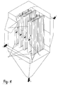
- an electrostatic filter is shown, which is suitable for filtering particles and / or droplets from a gas stream.
- the particulate contaminated gas entering the filter is indicated by an arrow numbered 1.
- the gas stream flows through the filter, whereby the particles in the gas are filtered out and removed.
- the outflowing, cleaned gas is indicated by the arrow with the reference numeral 2. Downstream, the flow of deposited particles 3 exits the filter.
- a cascade of electrodes is used. As can be seen in Fig. 1, a number of box-shaped electrodes 4 and 5 are arranged parallel to each other. Between the electrodes 4, 5 lanes 8 are provided, through which the gas to be purified 1 is passed.
- the electrodes 4, 5 are alternately connected either to a high voltage source (namely, the electrodes 4) or grounded (namely, the electrodes 5).
- all the electrodes 4, 5 are provided with a space, not designated here, into which the particles to be filtered out can enter, but in the extension of which no electrical potential difference prevails; he is therefore referred to here as a virtually electric field-free space.
- This space is created in the electrodes 4, 5 in that the Abscheideblech 7 is surrounded by a grid 6.
- Abscheideblech 7 and grid 6 are electrically connected.
- the grid 6 consists of a number of mutually parallel bars.
- the gas laden with particles initially flows in between the electrodes 4, 5 (see gas flow 1) and there comes under the effect of the quasi-homogeneous electric field.
- the particles are deflected in the direction of the electrodes and enter through the grid openings. Thus, they are in a virtually electric field free space, where they are no longer exposed to any further external electrostatic force. They fall down due to gravity and can be continuously - while the filter operation - removed from the filter.
- the cleaned gas leaves the filter in the horizontal direction via an outlet hood (see gas flow 2).
- the electrodes 4, 5 according to FIG. 1 show, by way of example, the creation of the electric-field-free space by the grid 6 composed of interconnected bars, which grid is electrically connected to the internal separator plate 7.
- the electrodes 4, 5 may be modular and arranged above and behind each other, as shown in Fig. 1. In this example, the electrodes on both sides of the Abscheidebleches a field-free space. Rand notede electrodes or in a filter with only one passage for the gas passage, the electrodes may also be constructed so that they only have a field-free space on one side of the Abscheidebleches. In any case, the depth of the field-free space depends on the requirements of the continuous particle withdrawal.
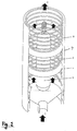
- Fig. 2 an alternative embodiment of this type of electric filter is sketched as a tube filter.
- the grounded electrode 5 contains the virtually field-free space 9, which is bounded here by a ring grid 6 and the cylindrical deposition plate 7.
- the grid 6 is formed here by a number of interconnected parallel arranged metal rings, which are electrically connected to the Abscheideblech 7 and together form the electrode 5.
- the electric field-free spaces 9 are formed as flow-calmed zones. This can be achieved by appropriate geometric arrangement of the bars or grid rings and / or a corresponding design of the gas inlet and the gas outlet.
- FIGS. 3 a and 3 b show a few details of the configuration of the electrodes 4, 5 with the deposition plate 7, the grid 6 and the quasi electrically field-free spaces 9 defined thereby.
- the Abscheidebleche 7 are plate-shaped and enclosed by rod-shaped grid elements which form the grid 6. Between the Abscheideblechen 7 and the grid 6, the largely electric field-free space 9 is formed in the electrodes 4, 5. The filtered particles move in the direction of arrow 3 (direction of gravity) down and can be removed from the electrostatic precipitator.
- FIG. 3b shows a double-walled embodiment of the electrodes 4, 5 for assisting the discharge of the particles from the filter.
- the particles which are located in largely electrically field-free space 9 sink downwards due to gravity and are guided through baffles and slits of the double-walled separating plate 7 into an internally protected intermediate space, namely into a discharge channel 10. There, they can be led out of the electrostatic precipitator, uninfluenced by the outer gas flow.
- the illustrated construction of the electrodes can be provided in principle in a horizontally and vertically flowed through electrostatic precipitator, with straight, curved, folded or round electrodes can be used.
- the formation of the electrodes and the height of the voltage are coordinated so that no increase in the electric field strength occurs, which leads to a corona or external partial discharges.
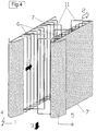
- FIG. 4 shows a section of an alley of a horizontally flowed through electrostatic precipitator is shown.
- the grid 6 here formed of wire hangers used.
- the body 11 are shown. They are constructed here of wire brackets, which are conductively connected to the respective electrodes (4,5).
- the straight wires are arranged perpendicular to the gas flow.
- the bodies can also be arranged parallel to the gas flow or at all angles between perpendicular and parallel to the gas flow.
Landscapes
- Electrostatic Separation (AREA)
- Filtering Materials (AREA)
Claims (15)
- Filtre travaillant de manière électrostatique pour la séparation de particules d'un gaz (1), lequel présente au moins une électrode (4) raccordée à une source de haute tension et au moins une électrode (5) mise à la terre ou de polarisation contraire, entre lesquelles on peut faire passer le gaz chargé de particules,
caractérisé en ce que
l'électrofiltre ne comprend pas d'électrode à couronne, et en ce que les électrodes (4, 5) sont réalisées avec un espace ouvert (9) au moins au niveau d'une extrémité de son étendue longitudinale et aménagé à la manière d'un grillage et à champ quasi nul, dans lequel les particules peuvent pénétrer via des ouvertures du grillage et duquel elles peuvent sortir au niveau de l'extrémité ouverte. - Filtre travaillant de manière électrostatique selon la revendication 1,
caractérisé en ce que
les électrodes mises à la terre peuvent présenter une configuration similaire à celle des électrodes sous haute tension. - Filtre travaillant de manière électrostatique selon la revendication 1,
caractérisé en ce que
les particules peuvent être continuellement évacuées des espaces à champ nul des électrodes. - Filtre travaillant de manière électrostatique selon les revendications 1 à 3,
caractérisé en ce que
seulement l'une au moins des électrodes (4) raccordée à la source de haute tension, et de préférence toutes les électrodes (4) raccordées à la source de haute tension, comprend et/ou comprennent un espace (9) à champ quasi nul. - Filtre travaillant de manière électrostatique selon les revendications 1 à 3,
caractérisé en ce que
seulement l'une au moins des électrodes (5) mise à la terre ou de polarisation contraire, et de préférence toutes les électrodes (5), comprend et/ou comprennent un tel espace (9). - Filtre travaillant de manière électrostatique selon les revendications 1 à 3,
caractérisé en ce que
l'une au moins des électrodes (4) raccordée à la source de haute tension tout comme également l'une au moins des électrodes (5) mise à la terre ou de polarisation contraire, et de préférence toutes les électrodes (4, 5), comprennent un tel espace (9). - Filtre travaillant de manière électrostatique selon l'une des revendications 1 à 6,
caractérisé en ce que
l'espace (9) est au moins partiellement délimité par un grillage (6), un filet, ou un complexe similaire, lequel est ouvert pour laisser passer des particules, et présente dans ce cas seulement un rétrécissement minime de la section transversale, et lequel est relié de manière électroconductrice avec la tôle de séparation (7) et forme avec celle-ci l'électrode (4, 5). - Filtre travaillant de manière électrostatique selon la revendication 7,
caractérisé en ce que
le grillage (6) se compose d'un certain nombre de tiges reliées ensemble et disposées parallèlement les unes aux autres, moyennant quoi celles-ci sont reliées de manière électroconductrice à une tôle de séparation (7) réalisée en forme de plaque et forment avec celle-ci l'électrode (4, 5). - Filtre travaillant de manière électrostatique selon la revendication 7,
caractérisé en ce que
le grillage (6) se compose d'un certain nombre d'anneaux reliés ensembles et disposés parallèlement les uns par rapport aux autres, moyennant quoi ceux-ci sont reliés de manière électroconductrice à une tôle de séparation (7) cylindrique ou bien cylindrique creuse, et forment avec celle-ci l'électrode (4, 5). - Filtre travaillant de manière électrostatique selon l'une quelconque des revendications 1 à 8,
caractérisé en ce que
il est réalisé en tant qu'électrofiltre à plaques, pour lequel un certain nombre d'électrodes (4, 5) réalisées en forme de plaques sont disposées parallèlement les unes par rapport aux autres. - Filtre travaillant de manière électrostatique selon l'une quelconque des revendications 1 à 7 ou 9,
caractérisé en ce que
il est réalisé en tant qu'électrofiltre à tubes, pour lequel au moins deux électrodes (4, 5) réalisées de manière cylindrique ou cylindrique creuse sont disposées coaxialement l'une par rapport à l'autre. - Filtre travaillant de manière électrostatique selon l'une quelconque des revendications 1 à 11,
caractérisé en ce que
au moins une électrode (4, 5) présente un canal d'évacuation (10) pour particules, lequel jouxte l'espace (9). - Filtre travaillant de manière électrostatique selon l'une quelconque des revendications 1 à 12,
caractérisé en ce que
des corps (13) avec une polarité alternante sont disposés dans l'espace entre les électrodes, lesquels sont reliés de manière électroconductrice en fonction de leurs polarités respectives à l'une des deux électrodes (4, 5) adjacentes des gaz en circulation. Les corps peuvent dans ce cas se situer selon tous les angles compris entre 0° et 90° par rapport à la direction de circulation du gaz. - Procédé pour la séparation de particules d'un gaz (1) à l'aide d'un filtre travaillant de manière électrostatique, lequel présente au moins une électrode (4) raccordée à une source de haute tension et au moins une électrode (5) mise à la terre ou de polarisation contraire, entre lesquelles on fait passer le gaz chargé de particules,
caractérisé en ce que
les particules sont déviées vers l'une des deux électrodes (4, 5), et en ce que les particules gagnent un espace aménagé à la manière d'un grillage (5) de l'électrode, dans l'étendue duquel il n'y a pas de différence de potentiel électrique, et en ce qu'elles y sont évacuées, moyennant quoi le filtre fonctionne sans électrode à couronne. - Procédé selon la revendication 14,
caractérisé en ce que
l'une au moins des électrodes (4) raccordée à la source de haute tension est alimentée avec une tension, laquelle est inférieure à la tension de coupure de couronne.
Applications Claiming Priority (3)
| Application Number | Priority Date | Filing Date | Title |
|---|---|---|---|
| DE10245902 | 2002-09-30 | ||
| DE10245902A DE10245902A1 (de) | 2002-09-30 | 2002-09-30 | Elektrostatisch arbeitendes Filter und Verfahren zum Abscheiden von Partikeln aus einem Gas |
| PCT/EP2003/010830 WO2004030825A1 (fr) | 2002-09-30 | 2003-09-30 | Filtre electrostatique et procede permettant de separer les particules d'un gaz |
Publications (2)
| Publication Number | Publication Date |
|---|---|
| EP1545785A1 EP1545785A1 (fr) | 2005-06-29 |
| EP1545785B1 true EP1545785B1 (fr) | 2006-07-26 |
Family
ID=31984350
Family Applications (1)
| Application Number | Title | Priority Date | Filing Date |
|---|---|---|---|
| EP03750661A Expired - Lifetime EP1545785B1 (fr) | 2002-09-30 | 2003-09-30 | Filtre electrostatique et procede permettant de separer les particules d'un gaz |
Country Status (8)
| Country | Link |
|---|---|
| EP (1) | EP1545785B1 (fr) |
| AT (1) | ATE333942T1 (fr) |
| AU (1) | AU2003270294A1 (fr) |
| DE (2) | DE10245902A1 (fr) |
| DK (1) | DK1545785T3 (fr) |
| ES (1) | ES2268407T3 (fr) |
| WO (1) | WO2004030825A1 (fr) |
| ZA (1) | ZA200501859B (fr) |
Families Citing this family (7)
| Publication number | Priority date | Publication date | Assignee | Title |
|---|---|---|---|---|
| DE102004033816B3 (de) * | 2004-07-12 | 2006-02-09 | Fisia Babcock Environment Gmbh | Elektrofilter mit einem inneren, elektrisch inaktiven Bereich für Sprühelektroden |
| DE102007037984A1 (de) | 2007-08-10 | 2009-02-12 | Leibniz-Institut für Plasmaforschung und Technologie e.V. | Verfahren zur Textilreinigung und Desinfektion mittels Plasma und Plasmaschleuse |
| DE102017003855A1 (de) | 2017-04-20 | 2018-10-25 | Frank Grundmann | Vorrichtung zur Erhöhung der Stabilität am unteren Erdungsring bei Elektrofiltern |
| DE102017007787A1 (de) | 2017-08-17 | 2019-02-21 | Frank Grundmann | Vorrichtung zur Erleichterung der Ausrichtung von Elektroden bei Nass- Elektrofiltern |
| US11185871B2 (en) * | 2017-12-04 | 2021-11-30 | Exodraft a/s | Electrostatic precipitator system having a grid for collection of particles |
| DE102023206812A1 (de) * | 2023-07-18 | 2025-01-23 | Karlsruher Institut für Technologie (KIT), Körperschaft des öffentlichen Rechts | Luftfiltereinrichtung für eine Klimatisierungsanlage |
| DE102023206813A1 (de) * | 2023-07-18 | 2025-01-23 | Karlsruher Institut für Technologie (KIT), Körperschaft des öffentlichen Rechts | Luftfiltereinrichtung für eine Klimatisierungsanlage |
Family Cites Families (4)
| Publication number | Priority date | Publication date | Assignee | Title |
|---|---|---|---|---|
| FR963621A (fr) * | 1950-07-17 | |||
| DE2802965C2 (de) * | 1978-01-24 | 1983-12-01 | Manfred R. 8023 Pullach Burger | Filtervorrichtung zur Reinigung von Gasen |
| DE3723544A1 (de) * | 1987-07-16 | 1989-01-26 | Man Technologie Gmbh | Elektrostatischer filter zum reinigen von gasen |
| US6568245B2 (en) * | 2001-03-15 | 2003-05-27 | Tsi Incorporated | Evaporative electrical detector |
-
2002
- 2002-09-30 DE DE10245902A patent/DE10245902A1/de not_active Withdrawn
-
2003
- 2003-09-30 AU AU2003270294A patent/AU2003270294A1/en not_active Abandoned
- 2003-09-30 DK DK03750661T patent/DK1545785T3/da active
- 2003-09-30 ES ES03750661T patent/ES2268407T3/es not_active Expired - Lifetime
- 2003-09-30 EP EP03750661A patent/EP1545785B1/fr not_active Expired - Lifetime
- 2003-09-30 AT AT03750661T patent/ATE333942T1/de active
- 2003-09-30 DE DE50304383T patent/DE50304383D1/de not_active Expired - Lifetime
- 2003-09-30 WO PCT/EP2003/010830 patent/WO2004030825A1/fr not_active Ceased
-
2005
- 2005-03-03 ZA ZA200501859A patent/ZA200501859B/xx unknown
Also Published As
| Publication number | Publication date |
|---|---|
| DK1545785T3 (da) | 2006-11-20 |
| DE50304383D1 (de) | 2006-09-07 |
| ATE333942T1 (de) | 2006-08-15 |
| EP1545785A1 (fr) | 2005-06-29 |
| ZA200501859B (en) | 2006-11-29 |
| ES2268407T3 (es) | 2007-03-16 |
| AU2003270294A1 (en) | 2004-04-23 |
| DE10245902A1 (de) | 2004-04-08 |
| WO2004030825A1 (fr) | 2004-04-15 |
Similar Documents
| Publication | Publication Date | Title |
|---|---|---|
| DE69508810T2 (de) | Elektrostatischer Abscheider | |
| EP0185966B1 (fr) | Procédé et dispositif de dépoussiérage d'un courant de gaz contenant des particules solides ou liquides au moyen d'un champ électrique | |
| DE3529057C2 (fr) | ||
| EP2155398B1 (fr) | Procédé et dispositif pour extraire des impuretés d'un courant gazeux | |
| DE2810735C2 (de) | Elektrische Gasreinigungsvorrichtung | |
| EP2744597B1 (fr) | Séparateur électronique de fines poussières | |
| AT408843B (de) | Staubfilter | |
| DE102011052946B4 (de) | Elektroabscheider | |
| DE2462539A1 (de) | Elektrische staubsammelvorrichtung | |
| CH673237A5 (fr) | ||
| DE2814610A1 (de) | Entstaubungseinrichtung fuer einen elektrofilter | |
| WO2004030825A1 (fr) | Filtre electrostatique et procede permettant de separer les particules d'un gaz | |
| EP0345309B1 (fr) | Filtre electrostatique pour la separation continue de particules solides ou fluides en suspension dans un courant de gaz | |
| DE102011110805A1 (de) | Elektronischer Feinstaubabscheider | |
| DE2235531C3 (de) | Verfahren und Einrichtung zum Abscheiden von feinsten Fremdstoffpartikeln aus einem Gasstrom | |
| DE2216436A1 (de) | Staubfiltervorrichtung | |
| EP4000738B1 (fr) | Filtre de nettoyage d'un flux gazeux | |
| DE102012004270A1 (de) | Vorrichtung zur Behandlung eines von einem Zentralbereich radial nach außen strömenden Gasstroms | |
| DE1557087A1 (de) | Elektrostatische Vorrichtung zum Ausfaellen | |
| DE19613720C2 (de) | Staubabscheidevorrichtung und Verfahren zum Staubabscheiden für einen Elektrofilter | |
| EP0658380A1 (fr) | Dispositif pour la séparation de particules de poussière des gaz effluents | |
| DE2460962A1 (de) | Elektrostatischer staubabscheider | |
| DE2102333C2 (de) | Elektroabscheider für einen Staubgasstrom | |
| DE202011104657U1 (de) | Elektronischer Feinstaubabscheider | |
| DE102012013996A1 (de) | Vorrichtung zum Abscheiden von Feststoffpartikeln und Beschichtungsanlage mit einer solchen |
Legal Events
| Date | Code | Title | Description |
|---|---|---|---|
| PUAI | Public reference made under article 153(3) epc to a published international application that has entered the european phase |
Free format text: ORIGINAL CODE: 0009012 |
|
| 17P | Request for examination filed |
Effective date: 20050309 |
|
| AK | Designated contracting states |
Kind code of ref document: A1 Designated state(s): AT BE BG CH CY CZ DE DK EE ES FI FR GB GR HU IE IT LI LU MC NL PT RO SE SI SK TR |
|
| AX | Request for extension of the european patent |
Extension state: AL LT LV MK |
|
| RAP1 | Party data changed (applicant data changed or rights of an application transferred) |
Owner name: FISIA BABCOCK ENVIRONMENT GMBH |
|
| DAX | Request for extension of the european patent (deleted) | ||
| GRAP | Despatch of communication of intention to grant a patent |
Free format text: ORIGINAL CODE: EPIDOSNIGR1 |
|
| GRAS | Grant fee paid |
Free format text: ORIGINAL CODE: EPIDOSNIGR3 |
|
| GRAA | (expected) grant |
Free format text: ORIGINAL CODE: 0009210 |
|
| REG | Reference to a national code |
Ref country code: DE Ref legal event code: R081 Ref document number: 50304383 Country of ref document: DE Owner name: FISIA BABCOCK ENVIRONMENT GMBH, DE Free format text: FORMER OWNER: HOCHSCHULE FUER ANGEWANDTE WISSENSCHAFTEN HAMBURG KOERPERSCHAFT DES OEFFENTLICHEN RECHTS, 20099 HAMBURG, DE |
|
| AK | Designated contracting states |
Kind code of ref document: B1 Designated state(s): AT BE BG CH CY CZ DE DK EE ES FI FR GB GR HU IE IT LI LU MC NL PT RO SE SI SK TR |
|
| PG25 | Lapsed in a contracting state [announced via postgrant information from national office to epo] |
Ref country code: SI Free format text: LAPSE BECAUSE OF FAILURE TO SUBMIT A TRANSLATION OF THE DESCRIPTION OR TO PAY THE FEE WITHIN THE PRESCRIBED TIME-LIMIT Effective date: 20060726 Ref country code: SK Free format text: LAPSE BECAUSE OF FAILURE TO SUBMIT A TRANSLATION OF THE DESCRIPTION OR TO PAY THE FEE WITHIN THE PRESCRIBED TIME-LIMIT Effective date: 20060726 Ref country code: IE Free format text: LAPSE BECAUSE OF FAILURE TO SUBMIT A TRANSLATION OF THE DESCRIPTION OR TO PAY THE FEE WITHIN THE PRESCRIBED TIME-LIMIT Effective date: 20060726 |
|
| REG | Reference to a national code |
Ref country code: GB Ref legal event code: FG4D Free format text: NOT ENGLISH |
|
| REG | Reference to a national code |
Ref country code: CH Ref legal event code: EP |
|
| REG | Reference to a national code |
Ref country code: IE Ref legal event code: FG4D Free format text: LANGUAGE OF EP DOCUMENT: GERMAN |
|
| REG | Reference to a national code |
Ref country code: SE Ref legal event code: TRGR |
|
| REF | Corresponds to: |
Ref document number: 50304383 Country of ref document: DE Date of ref document: 20060907 Kind code of ref document: P |
|
| REG | Reference to a national code |
Ref country code: DE Ref legal event code: R096 Ref document number: 50304383 Country of ref document: DE Effective date: 20060907 |
|
| PG25 | Lapsed in a contracting state [announced via postgrant information from national office to epo] |
Ref country code: MC Free format text: LAPSE BECAUSE OF NON-PAYMENT OF DUE FEES Effective date: 20060930 |
|
| REG | Reference to a national code |
Ref country code: RO Ref legal event code: EPE |
|
| PG25 | Lapsed in a contracting state [announced via postgrant information from national office to epo] |
Ref country code: BG Free format text: LAPSE BECAUSE OF FAILURE TO SUBMIT A TRANSLATION OF THE DESCRIPTION OR TO PAY THE FEE WITHIN THE PRESCRIBED TIME-LIMIT Effective date: 20061026 |
|
| REG | Reference to a national code |
Ref country code: CH Ref legal event code: NV Representative=s name: SCHMAUDER & PARTNER AG PATENTANWALTSBUERO |
|
| REG | Reference to a national code |
Ref country code: DK Ref legal event code: T3 |
|
| GBT | Gb: translation of ep patent filed (gb section 77(6)(a)/1977) |
Effective date: 20061030 |
|
| PG25 | Lapsed in a contracting state [announced via postgrant information from national office to epo] |
Ref country code: PT Free format text: LAPSE BECAUSE OF FAILURE TO SUBMIT A TRANSLATION OF THE DESCRIPTION OR TO PAY THE FEE WITHIN THE PRESCRIBED TIME-LIMIT Effective date: 20061226 |
|
| REG | Reference to a national code |
Ref country code: HU Ref legal event code: AG4A Ref document number: E000863 Country of ref document: HU |
|
| REG | Reference to a national code |
Ref country code: IE Ref legal event code: FD4D |
|
| ET | Fr: translation filed | ||
| REG | Reference to a national code |
Ref country code: ES Ref legal event code: FG2A Ref document number: 2268407 Country of ref document: ES Kind code of ref document: T3 |
|
| PLBE | No opposition filed within time limit |
Free format text: ORIGINAL CODE: 0009261 |
|
| STAA | Information on the status of an ep patent application or granted ep patent |
Free format text: STATUS: NO OPPOSITION FILED WITHIN TIME LIMIT |
|
| 26N | No opposition filed |
Effective date: 20070427 |
|
| REG | Reference to a national code |
Ref country code: DE Ref legal event code: R097 Ref document number: 50304383 Country of ref document: DE Effective date: 20070427 |
|
| PG25 | Lapsed in a contracting state [announced via postgrant information from national office to epo] |
Ref country code: GR Free format text: LAPSE BECAUSE OF FAILURE TO SUBMIT A TRANSLATION OF THE DESCRIPTION OR TO PAY THE FEE WITHIN THE PRESCRIBED TIME-LIMIT Effective date: 20061027 |
|
| PG25 | Lapsed in a contracting state [announced via postgrant information from national office to epo] |
Ref country code: EE Free format text: LAPSE BECAUSE OF FAILURE TO SUBMIT A TRANSLATION OF THE DESCRIPTION OR TO PAY THE FEE WITHIN THE PRESCRIBED TIME-LIMIT Effective date: 20060726 |
|
| PG25 | Lapsed in a contracting state [announced via postgrant information from national office to epo] |
Ref country code: LU Free format text: LAPSE BECAUSE OF NON-PAYMENT OF DUE FEES Effective date: 20060930 Ref country code: TR Free format text: LAPSE BECAUSE OF FAILURE TO SUBMIT A TRANSLATION OF THE DESCRIPTION OR TO PAY THE FEE WITHIN THE PRESCRIBED TIME-LIMIT Effective date: 20060726 |
|
| PGFP | Annual fee paid to national office [announced via postgrant information from national office to epo] |
Ref country code: CH Payment date: 20080915 Year of fee payment: 6 Ref country code: DK Payment date: 20080912 Year of fee payment: 6 |
|
| PG25 | Lapsed in a contracting state [announced via postgrant information from national office to epo] |
Ref country code: CY Free format text: LAPSE BECAUSE OF FAILURE TO SUBMIT A TRANSLATION OF THE DESCRIPTION OR TO PAY THE FEE WITHIN THE PRESCRIBED TIME-LIMIT Effective date: 20060726 |
|
| PGFP | Annual fee paid to national office [announced via postgrant information from national office to epo] |
Ref country code: FI Payment date: 20080915 Year of fee payment: 6 |
|
| PGFP | Annual fee paid to national office [announced via postgrant information from national office to epo] |
Ref country code: HU Payment date: 20080908 Year of fee payment: 6 |
|
| PGFP | Annual fee paid to national office [announced via postgrant information from national office to epo] |
Ref country code: BE Payment date: 20081001 Year of fee payment: 6 |
|
| REG | Reference to a national code |
Ref country code: CH Ref legal event code: PCAR Free format text: SCHMAUDER & PARTNER AG PATENT- UND MARKENANWAELTE VSP;ZWAENGIWEG 7;8038 ZUERICH (CH) |
|
| BERE | Be: lapsed |
Owner name: *FISIA BABCOCK ENVIRONMENT G.M.B.H. Effective date: 20090930 |
|
| PG25 | Lapsed in a contracting state [announced via postgrant information from national office to epo] |
Ref country code: FI Free format text: LAPSE BECAUSE OF NON-PAYMENT OF DUE FEES Effective date: 20090930 |
|
| REG | Reference to a national code |
Ref country code: CH Ref legal event code: PL |
|
| REG | Reference to a national code |
Ref country code: DK Ref legal event code: EBP |
|
| PG25 | Lapsed in a contracting state [announced via postgrant information from national office to epo] |
Ref country code: HU Free format text: LAPSE BECAUSE OF NON-PAYMENT OF DUE FEES Effective date: 20091001 |
|
| PG25 | Lapsed in a contracting state [announced via postgrant information from national office to epo] |
Ref country code: BE Free format text: LAPSE BECAUSE OF NON-PAYMENT OF DUE FEES Effective date: 20090930 |
|
| PG25 | Lapsed in a contracting state [announced via postgrant information from national office to epo] |
Ref country code: LI Free format text: LAPSE BECAUSE OF NON-PAYMENT OF DUE FEES Effective date: 20090930 Ref country code: CH Free format text: LAPSE BECAUSE OF NON-PAYMENT OF DUE FEES Effective date: 20090930 |
|
| PGFP | Annual fee paid to national office [announced via postgrant information from national office to epo] |
Ref country code: RO Payment date: 20100830 Year of fee payment: 8 |
|
| PGFP | Annual fee paid to national office [announced via postgrant information from national office to epo] |
Ref country code: AT Payment date: 20100914 Year of fee payment: 8 Ref country code: FR Payment date: 20101005 Year of fee payment: 8 Ref country code: SE Payment date: 20100914 Year of fee payment: 8 |
|
| PGFP | Annual fee paid to national office [announced via postgrant information from national office to epo] |
Ref country code: GB Payment date: 20100921 Year of fee payment: 8 |
|
| PG25 | Lapsed in a contracting state [announced via postgrant information from national office to epo] |
Ref country code: DK Free format text: LAPSE BECAUSE OF NON-PAYMENT OF DUE FEES Effective date: 20090930 |
|
| PGFP | Annual fee paid to national office [announced via postgrant information from national office to epo] |
Ref country code: CZ Payment date: 20110922 Year of fee payment: 9 Ref country code: ES Payment date: 20110926 Year of fee payment: 9 |
|
| PGFP | Annual fee paid to national office [announced via postgrant information from national office to epo] |
Ref country code: NL Payment date: 20110929 Year of fee payment: 9 |
|
| GBPC | Gb: european patent ceased through non-payment of renewal fee |
Effective date: 20110930 |
|
| REG | Reference to a national code |
Ref country code: FR Ref legal event code: ST Effective date: 20120531 |
|
| REG | Reference to a national code |
Ref country code: SE Ref legal event code: EUG |
|
| PG25 | Lapsed in a contracting state [announced via postgrant information from national office to epo] |
Ref country code: FR Free format text: LAPSE BECAUSE OF NON-PAYMENT OF DUE FEES Effective date: 20110930 Ref country code: GB Free format text: LAPSE BECAUSE OF NON-PAYMENT OF DUE FEES Effective date: 20110930 Ref country code: RO Free format text: LAPSE BECAUSE OF NON-PAYMENT OF DUE FEES Effective date: 20110930 |
|
| PG25 | Lapsed in a contracting state [announced via postgrant information from national office to epo] |
Ref country code: SE Free format text: LAPSE BECAUSE OF NON-PAYMENT OF DUE FEES Effective date: 20111001 |
|
| REG | Reference to a national code |
Ref country code: AT Ref legal event code: MM01 Ref document number: 333942 Country of ref document: AT Kind code of ref document: T Effective date: 20110930 |
|
| PG25 | Lapsed in a contracting state [announced via postgrant information from national office to epo] |
Ref country code: AT Free format text: LAPSE BECAUSE OF NON-PAYMENT OF DUE FEES Effective date: 20110930 |
|
| REG | Reference to a national code |
Ref country code: NL Ref legal event code: V1 Effective date: 20130401 |
|
| PG25 | Lapsed in a contracting state [announced via postgrant information from national office to epo] |
Ref country code: CZ Free format text: LAPSE BECAUSE OF NON-PAYMENT OF DUE FEES Effective date: 20120930 |
|
| PG25 | Lapsed in a contracting state [announced via postgrant information from national office to epo] |
Ref country code: NL Free format text: LAPSE BECAUSE OF NON-PAYMENT OF DUE FEES Effective date: 20130401 |
|
| REG | Reference to a national code |
Ref country code: ES Ref legal event code: FD2A Effective date: 20131023 |
|
| PG25 | Lapsed in a contracting state [announced via postgrant information from national office to epo] |
Ref country code: ES Free format text: LAPSE BECAUSE OF NON-PAYMENT OF DUE FEES Effective date: 20121001 |
|
| PGFP | Annual fee paid to national office [announced via postgrant information from national office to epo] |
Ref country code: IT Payment date: 20140929 Year of fee payment: 12 |
|
| PG25 | Lapsed in a contracting state [announced via postgrant information from national office to epo] |
Ref country code: IT Free format text: LAPSE BECAUSE OF NON-PAYMENT OF DUE FEES Effective date: 20150930 |
|
| PGFP | Annual fee paid to national office [announced via postgrant information from national office to epo] |
Ref country code: DE Payment date: 20230216 Year of fee payment: 20 |
|
| P01 | Opt-out of the competence of the unified patent court (upc) registered |
Effective date: 20230517 |
|
| REG | Reference to a national code |
Ref country code: DE Ref legal event code: R071 Ref document number: 50304383 Country of ref document: DE |