EP1545976B1 - Procede et machine d'emballage d'un produit dans un paquet tubulaire plat - Google Patents
Procede et machine d'emballage d'un produit dans un paquet tubulaire plat Download PDFInfo
- Publication number
- EP1545976B1 EP1545976B1 EP03784203A EP03784203A EP1545976B1 EP 1545976 B1 EP1545976 B1 EP 1545976B1 EP 03784203 A EP03784203 A EP 03784203A EP 03784203 A EP03784203 A EP 03784203A EP 1545976 B1 EP1545976 B1 EP 1545976B1
- Authority
- EP
- European Patent Office
- Prior art keywords
- gripping head
- tubular package
- suction gripping
- flat
- suction
- Prior art date
- Legal status (The legal status is an assumption and is not a legal conclusion. Google has not performed a legal analysis and makes no representation as to the accuracy of the status listed.)
- Expired - Lifetime
Links
- 238000000034 method Methods 0.000 title claims abstract description 21
- 238000012856 packing Methods 0.000 title claims abstract description 11
- 235000019504 cigarettes Nutrition 0.000 claims abstract description 23
- 238000007789 sealing Methods 0.000 claims abstract description 15
- 238000003780 insertion Methods 0.000 claims description 14
- 230000037431 insertion Effects 0.000 claims description 14
- 239000002390 adhesive tape Substances 0.000 claims description 4
- 230000003287 optical effect Effects 0.000 description 2
- 239000013013 elastic material Substances 0.000 description 1
- 230000000737 periodic effect Effects 0.000 description 1
Images

Classifications
-
- B—PERFORMING OPERATIONS; TRANSPORTING
- B65—CONVEYING; PACKING; STORING; HANDLING THIN OR FILAMENTARY MATERIAL
- B65B—MACHINES, APPARATUS OR DEVICES FOR, OR METHODS OF, PACKAGING ARTICLES OR MATERIALS; UNPACKING
- B65B5/00—Packaging individual articles in containers or receptacles, e.g. bags, sacks, boxes, cartons, cans, jars
- B65B5/02—Machines characterised by incorporation of means for making the containers or receptacles
- B65B5/024—Machines characterised by incorporation of means for making the containers or receptacles for making containers from preformed blanks
-
- B—PERFORMING OPERATIONS; TRANSPORTING
- B65—CONVEYING; PACKING; STORING; HANDLING THIN OR FILAMENTARY MATERIAL
- B65B—MACHINES, APPARATUS OR DEVICES FOR, OR METHODS OF, PACKAGING ARTICLES OR MATERIALS; UNPACKING
- B65B43/00—Forming, feeding, opening or setting-up containers or receptacles in association with packaging
- B65B43/26—Opening or distending bags; Opening, erecting, or setting-up boxes, cartons, or carton blanks
- B65B43/265—Opening, erecting or setting-up boxes, cartons or carton blanks
-
- B—PERFORMING OPERATIONS; TRANSPORTING
- B31—MAKING ARTICLES OF PAPER, CARDBOARD OR MATERIAL WORKED IN A MANNER ANALOGOUS TO PAPER; WORKING PAPER, CARDBOARD OR MATERIAL WORKED IN A MANNER ANALOGOUS TO PAPER
- B31B—MAKING CONTAINERS OF PAPER, CARDBOARD OR MATERIAL WORKED IN A MANNER ANALOGOUS TO PAPER
- B31B2100/00—Rigid or semi-rigid containers made by folding single-piece sheets, blanks or webs
-
- B—PERFORMING OPERATIONS; TRANSPORTING
- B31—MAKING ARTICLES OF PAPER, CARDBOARD OR MATERIAL WORKED IN A MANNER ANALOGOUS TO PAPER; WORKING PAPER, CARDBOARD OR MATERIAL WORKED IN A MANNER ANALOGOUS TO PAPER
- B31B—MAKING CONTAINERS OF PAPER, CARDBOARD OR MATERIAL WORKED IN A MANNER ANALOGOUS TO PAPER
- B31B2120/00—Construction of rigid or semi-rigid containers
- B31B2120/30—Construction of rigid or semi-rigid containers collapsible; temporarily collapsed during manufacturing
-
- B—PERFORMING OPERATIONS; TRANSPORTING
- B31—MAKING ARTICLES OF PAPER, CARDBOARD OR MATERIAL WORKED IN A MANNER ANALOGOUS TO PAPER; WORKING PAPER, CARDBOARD OR MATERIAL WORKED IN A MANNER ANALOGOUS TO PAPER
- B31B—MAKING CONTAINERS OF PAPER, CARDBOARD OR MATERIAL WORKED IN A MANNER ANALOGOUS TO PAPER
- B31B50/00—Making rigid or semi-rigid containers, e.g. boxes or cartons
- B31B50/74—Auxiliary operations
- B31B50/76—Opening and distending flattened articles
- B31B50/80—Pneumatically
Definitions
- the present invention relates to a method and to a machine for packing a product in a flat tubular package.
- the present invention may be used to advantage on a cigarette carton boxing machine, i.e. a machine for packing groups of cartons of cigarettes in respective boxes, to which the following description refers purely by way of example.
- Machines for boxing cartons of cigarettes currently comprise a unit for supplying and opening flat tubular packages, and which receives a stack of flat tubular packages on a pallet, and feeds each flat tubular package to a respective seat on a conveyor, which feeds the tubular package along a straight packing path.
- each tubular package remains connected to the respective seat, and is fed through an opening station, where the tubular package is opened into a configuration suitable for receiving a respective group of cartons of cigarettes; through an insertion station, where a respective group of cartons of cigarettes is pushed inside the open tubular package; and, finally, through a sealing station, where the tubular package is sealed by gumming and folding the relative flaps.
- WO8900132 discloses a carton loading and closing machine comprising a carton opening mechanism adapted to remove a flat carton from a magazine to a park position, means for folding the side flaps at the bottom of the carton outwardly, means for loading product into carton through its open bottom, means for indexing the loaded carton forwardly over cam means for folding the leading end flap under the product, trailing end flap closing means having a slot adapted to receive the trailing end flap and means for causing said trailing end flap to be folded to the closed position as said folding means is moved transversely with respect to the stationary carton, and means for closing the side flaps and the top flaps of the carton.
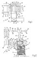
- Number 1 in Figure 1 indicates as a whole a boxing machine for boxing groups 2 of cartons of cigarettes, and which inserts each group 2 of cartons of cigarettes inside a respective tubular package 3 having two major lateral walls 4; and two minor lateral walls 5, each connected on one side to one major lateral wall 4, and on the other side to the other major lateral wall 4, by respective preformed fold lines 6. More specifically, each major lateral wall 4 has two flaps 7, and each minor lateral wall 5 has two flaps 8; and, once group 2 of cartons of cigarettes is inserted inside a respective tubular package 3, the relative flaps 7 and 8 are folded one on top of another to define two end walls 9. Once flaps 7 and 8 are folded, the shape of tubular package 3 is preferably stabilized by applying respective lengths of adhesive tape 10 to both end walls 9.
- Boxing machine 1 comprises a pickup station 11, which houses a pallet 12 supporting a stack 13 of flat tubular packages 3, i.e. tubular packages 3 pressed into a flat configuration and lying in a horizontal plane.
- Boxing machine 1 also comprises a suction gripping head 14 for engaging the free major lateral wall 4 and the free minor lateral wall 5 of the top flat tubular package 3 in stack 13; and an actuating device 15 supporting gripping head 14, and for moving gripping head 14 from pickup station 11 to a sealing station 16 via an intermediate feed station 17.
- actuating device 15 moves gripping head 14 with four degrees of freedom comprising three translatory movements in three perpendicular directions 18, 19, 20 (18 shown in Figure 1); and a rotational movement about a vertical axis 21 perpendicular to the horizontal plane of flat tubular packages 3 in stack 13. More specifically, actuating device 15 comprises a guide 22 supported at the ends by two powered carriages 23, which run along respective guides 24 to move guide 22 in horizontal direction 18 perpendicular to the Figure 2 plane. A powered carriage 25 runs along guide 22, and supports a linear actuator 26 moved by carriage 25 in horizontal direction 19.
- Linear actuator 26 comprises a member 27 integral with carriage 25; and a member 28 supporting gripping head 14 and moved with respect to member 27 in vertical direction 20; and a powered articulated joint 29 is interposed between member 28 and gripping head 14 to rotate gripping head 14 about vertical axis 21.
- Actuating device 15 therefore maintains suction gripping head 14 horizontal at all times, and therefore parallel to the plane of flat tubular packages 3.
- Suction gripping head 14 comprises a suction portion 30 for engaging a major lateral wall 4 of a tubular package 3, and a suction portion 31, which engages a minor lateral wall 5 of a tubular package 3, is hinged to suction portion 30, and is rotated, with respect to suction portion 30, about a horizontal axis 32 by an actuating device 33 carried by suction gripping head 14. More specifically, suction portions 30 and 31 of gripping head 14 have respective known suction cups 34 made of deformable elastic material and connectable internally to a known suction source (not shown).
- the axis of rotation 32 between portions 30 and 31 does not coincide with the fold line 6 between lateral walls 4 and 5 engaged by gripping head 14, and suction cups 34 of portion 30 are fitted to portion 30 so as to slide in a direction perpendicular to axis of rotation 32 (not shown).
- suction gripping head 14 comprises a known optical sensor 35 for determining the exact position of the top flat tubular package 3 in stack 13 before the flat tubular package 3 is engaged; and a known control unit (not shown) is provided to control actuating device 15 supporting suction gripping head 14, so as to adapt the position of suction gripping head 14 to the exact position reading of flat tubular package 3, and engage the flat tubular package 3 in accordance with a given mutual arrangement. Actuating device 15 thus provides for correcting any errors in the position of flat tubular packages 3 in stack 13.
- pickup station 11 is located beneath feed station 17, where an insertion device 36 inserts a group 2 of cartons of cigarettes inside a respective open tubular package 3 supported by suction gripping head 14.
- Insertion device 36 comprises a belt conveyor 37 for feeding groups 2 of cartons of cigarettes successively into alignment with the open tubular package 3 at feed station 17; and a pusher 38 for pushing group 2 of cartons of cigarettes inside the open tubular package 3.
- Fixed sections 39 are preferably provided between conveyor 37 and tubular package 3 to assist insertion of group 2 of cartons of cigarettes inside respective open tubular package 3, and in particular to keep flaps 7 and 8 of tubular package 3 clear of the path of group 2 of cartons of cigarettes.
- Sealing station 16 is located alongside and on a level with feed station 17, and comprises a belt conveyor 40, in turn comprising two suction belts 41 looped about respective powered end pulleys 42 to define a channel 43 for receiving and conveying an open tubular package 3 containing a respective group 2 of cartons of cigarettes.
- Conveyor 40 is hinged to rotate, under control of a known motor (not shown) and about a horizontal axis 44, between a horizontal position (shown by the continuous line in Figure 2) wherein conveyor 40 feeds a tubular package 3 along a horizontal path inside channel 43, and a vertical position (shown by the dash line in Figure 2) wherein conveyor 40 feeds a tubular package 3 along a vertical path inside channel 43.
- conveyor 40 In the horizontal position, conveyor 40 is connected to two known sealing devices 45 located on opposite sides of conveyor 40, and which fold down, one on top of another, the flaps 7 and 8 of a tubular package 3 travelling inside channel 43, and apply respective lengths of adhesive tape 10 to the folded flaps 7 and 8 to define end walls 9 of tubular package 3.
- conveyor 40 In the vertical position, conveyor 40 is aligned with a follow-up belt conveyor 46, which receives the sealed tubular packages 3 from conveyor 40, and feeds tubular packages 3 to a known output station (not shown) of boxing machine 1.
- conveyor 40 is fixed, and conveyor 46 is aligned horizontally with conveyor 40.
- sealing devices 45 are located at feed station 17 to seal the tubular package 3 at feed station 17, as soon as a respective group 2 of cartons of cigarettes is inserted by insertion device 36 inside the open tubular package 3.
- boxing machine 1 Operation of boxing machine 1 will now be described with reference to the top flat tubular package 3 in stack 13, and to a respective group 2 of cartons of cigarettes.
- actuating device 15 moves suction gripping head 14 over to pickup station 11 to engage the flat tubular package 3, and so that suction portion 30 of suction gripping head 14 engages major lateral wall 4 of flat tubular package 3, and suction portion 31 of suction gripping head 14 engages minor lateral wall 5 of flat tubular package 3. More specifically, actuating devices 15 moves suction gripping head 14 over to roughly the estimated position of flat tubular package 3 (i.e.
- suction gripping head 14 determines the real position of flat tubular package 3; and, on the basis of the real-position reading of flat tubular package 3, actuating device 15 is operated to adapt the position of suction gripping head 14 to the real position of flat tubular package 3, and so enable gripping head 14 to engage flat tubular package 3 in accordance with a given mutual arrangement.
- Actuating device 15 then moves suction gripping head 14, together with flat tubular package 3, from pickup station 11 to feed station 17. And, as it is being transferred from pickup station 11 to feed station 17, tubular package 3 is converted from the flat configuration to an open configuration by rotating portion 31 of suction gripping head 14 ninety degrees about axis 32 with respect to portion 30 of suction gripping head 14.
- Actuating device 15 moves suction gripping head 14, engaging tubular package 3, into feed station 17, so as to align the open tubular package 3 with insertion device 36. Since feed station 17 is located over pickup station 11, the above transfer is made by a main movement in vertical direction 20, by small adjusting movements in the other horizontal directions 18 and 19, and by small rotations about axis 21.
- tubular package 3 is aligned with insertion device 36, pusher 38 of insertion device 36 is moved to insert group 2 of cartons of cigarettes inside the open tubular package 3.
- Actuating device 15 then moves suction gripping head 14, engaging the open tubular package 3 containing group 2 of cartons of cigarettes, to feed tubular package 3 to sealing station 16, by inserting the open tubular package 3 inside channel 43 of conveyor 40.
- suction head 14 releases tubular package 3 by cutting off suction through suction cups 34, and actuating device 15 is returned to pickup station 11.
- the bottom belt 41 of conveyor 40 is longer than the top belt 41 of conveyor 40.
- Conveyor 40 then feeds the open tubular package 3 inside channel 43, so that the open tubular package 3 cooperates with sealing devices 45, which fold flaps 7 and 8 of tubular package 3 down one on top of another, and apply respective lengths of adhesive tape 10 to the folded flaps 7 and 8.
- the open tubular package 3 is inserted inside channel 43 by gripping head 14, so that respective flaps 7 and 8 project laterally from channel 43.
- the sealed tubular package 3 is transferred from conveyor 40 to conveyor 46, and from this to the output station (not shown) and off boxing machine 1.
- a further suction gripping head 47 is fitted to an arm 48 rotated horizontally by an actuating device 49 about a vertical axis 50.
- suction gripping head 14 together with flat tubular package 3, is moved by actuating device 15 from pickup station 11 to feed station 17, actuating device 49 rotates arm 48 about axis 50 to move suction gripping head 47 into a work position ( Figures 2-5) engaging the bottom major lateral wall 4, i.e. the one opposite the major lateral wall 4 engaged by suction gripping head 14.
- tubular package 3 is converted from the flat to the open configuration by rotating portion 31 of suction gripping head 14 ninety degrees about axis 32 with respect to portion 30 of suction gripping head 14, and also by means of a relative rotation movement between suction gripping head 14 and suction gripping head 47, which is effected by keeping suction gripping head 47 stationary, and moving suction gripping head 14 by means of actuating device 15.
- suction gripping head 47 releases the bottom major lateral wall 4 of tubular package 3, and is restored by actuating device 49 to the rest position (not shown).
- Boxing machine 1 as described above has countless advantages, by being relatively straightforward and compact, and by operating with stacks 13 of flat tubular packages 3 which need not necessarily be positioned accurately, and which can therefore be fed fully automatically.
Landscapes
- Engineering & Computer Science (AREA)
- Mechanical Engineering (AREA)
- Supplying Of Containers To The Packaging Station (AREA)
- Container Filling Or Packaging Operations (AREA)
- Wrapping Of Specific Fragile Articles (AREA)
- Containers And Plastic Fillers For Packaging (AREA)
- Making Paper Articles (AREA)
Claims (30)
- Procédé d'emballage d'un produit (2) dans un paquet tubulaire plat (3) ayant deux premières parois latérales (4) ; et deux secondes parois latérales (5), chacune étant reliée sur un côté à une première paroi latérale (4), et sur l'autre côté à l'autre première paroi latérale (4), par des lignes de pliage préformées respectives (6) ; le procédé comprenant les étapes consistant à engager une première paroi latérale (4) du paquet tubulaire plat (3) et une seconde paroi latérale (5) du paquet tubulaire plat (3) au moyen d'une première partie (30) et d'une seconde partie (31) respectivement d'une première tête de saisie par aspiration (14), à générer un mouvement rotatif entre la première (30) et la seconde (31) parties de la première tête de saisie par aspiration (14), à faire tourner les première et secondes parois latérales (4, 5) engagées par la première tête de saisie par aspiration (14) l'une par rapport à l'autre, et ainsi à convertir le paquet tubulaire plat (3) de la configuration plate à une configuration ouverte, et à insérer le produit (2) à l'intérieur du paquet tubulaire ouvert (3) ; le procédé étant caractérisé en ce que le mouvement rotatif entre la première (30) et la seconde (31) parties de la première tête de saisie par aspiration (14) est fait autour d'un axe (32) de rotation ne coïncidant pas avec la ligne de pliage (6) entre les première et seconde parois latérales (4, 5) engagées par la première tête de saisie par aspiration (14) ; des ventouses (34) sur la seconde partie (31) se déplaçant dans une direction perpendiculaire à l'axe (32) de rotation pendant le mouvement rotatif entre la première (30) et la seconde (31) parties de la première tête de saisie par aspiration (14).
- Procédé selon la revendication 1, dans lequel le paquet tubulaire plat (3) est engagé par la première tête de saisie par aspiration (14) au niveau d'une station de prélèvement (11), et est transféré, fixé à la première tête de saisie par aspiration (14), à une station réceptrice (17) où le produit (2) est inséré à l'intérieur du paquet tubulaire ouvert(3) ; le paquet tubulaire plat (3) étant transformé de la configuration plate à la configuration ouverte pendant le transfert de la station de prélèvement (11) à la station réceptrice(17).
- Procédé selon la revendication 2, dans lequel, après l'insertion du produit (2) à l'intérieur du paquet tubulaire ouvert (3), la première tête de saisie par aspiration (14) engageant le paquet tubulaire ouvert (3) est déplacée pour apporter le paquet tubulaire ouvert (3) vers une station de scellement (16) où le paquet tubulaire ouvert (3) est scellé.
- Procédé selon la revendication 3, dans lequel la première tête de saisie par aspiration (14) transfert le paquet tubulaire ouvert (3) à des moyens transporteurs (40, 46) situés à la station de scellement (16) et pour apporter le paquet tubulaire ouvert (3) à travers la station de scellement (16) et jusqu'à une station de sortie.
- Procédé selon la revendication 2, dans lequel après l'insertion du produit (2) à l'intérieur du paquet tubulaire ouvert (3), le paquet tubulaire ouvert (3) est scellé à la station réceptrice (17), et la première tête de saisie par aspiration (14) engageant le paquet tubulaire scellé (3) est déplacée pour apporter le paquet tubulaire scellé (3) vers une station de sortie.
- Procédé selon l'une des revendications 3 à 5, dans lequel le paquet tubulaire ouvert (3) est scellé en pliant, l'un sur l'autre, des rabats (7, 8) faisant saillie depuis les première et seconde parois latérales (4, 5), et en appliquant des longueurs respectives (10) de ruban adhésif aux rabats pliés (7, 8).
- Procédé selon l'une des revendications 1 à 5, dans lequel le paquet tubulaire plat (3) est prélevé par la première tête de saisie par aspiration (14) hors d'une pile (13) de paquets tubulaires plats (3).
- Procédé selon la revendication 7, dans lequel, avant d'engager le paquet tubulaire plat supérieure (3) dans la pile (13), la première tête de saisie par aspiration (14) détermine la position exacte du paquet tubulaire plat (3), et adapte sa propre position en conséquence, afin d'engager le paquet tubulaire plat (3) conformément à tout agencement mutuel donné.
- Procédé selon la revendication 8, dans lequel la première tête de saisie par aspiration (14) est mobile avec quatre degrés de liberté comprenant trois mouvements translatoires dans trois directions perpendiculaires (18, 19, 20), et un mouvement rotatif autour d'un axe (21) perpendiculaire au plan du paquet tubulaire plat (3).
- Procédé selon l'une des revendications 1 à 9, comprenant les étapes consistant à engager une première paroi latérale (4) du paquet tubulaire plat (3) et une seconde paroi latérale (5) du paquet tubulaire plat (3) au moyen de la première partie (30) et de la seconde partie (31) respectivement de la première tête de saisie par aspiration (14), et également en engageant, au moyen d'une seconde tête de saisie par aspiration (47), la première paroi latérale (4), du paquet tubulaire plat (3) à l'opposé de la première paroi latérale (4) engagée par la première tête de saisie par aspiration (14) ; le paquet tubulaire plat (3) étant converti de la configuration plate à la configuration ouverte par le mouvement rotatif entre les première (30) et seconde (31) parties de la première tête de saisie par aspiration (14), et également par un mouvement rotatif relatif entre la première tête de saisie par aspiration (14) et la seconde tête de saisie par aspiration (47).
- Procédé selon la revendication 10, dans lequel une fois que le paquet tubulaire plat (3) est converti à la configuration ouverte, la seconde tête de saisie par aspiration (47) libère la première paroi latérale (4) du paquet tubulaire plat (3).
- Procédé selon la revendication 10 ou 11, dans lequel la seconde tête de saisie par aspiration (47) tourne autour d'un axe vertical (50) entre une position de repos permettant le mouvement vertical libre de la première tête de saisie par aspiration (14), et une position de travail dans laquelle la seconde tête de saisie par aspiration (47) engage le paquet tubulaire plat (3).
- Procédé selon la revendication 10, 11 ou 12, dans lequel le mouvement rotatif relatif entre la première tête de saisie par aspiration (14) et la seconde tête de saisie par aspiration (47) est fait en maintenant la seconde tête de saisie par aspiration (47) fixe, et en déplaçant la première tête de saisie par aspiration (14).
- Procédé selon l'une des revendications 1 à 13, dans lequel le produit (2) est défini par un groupe (2) de cartouches de cigarettes.
- Machine pour emballer un produit (2) dans un paquet tubulaire plat (3) ayant deux premières parois latérales (4) ; et deux secondes parois latérales (5), chacune étant reliée sur un côté à une première paroi latérale (4), et sur l'autre côté à l'autre première paroi latérale (4), par des lignes de pliage préformées respectives (6) ; la machine (1) comprenant une première tête de saisie par aspiration (14) ayant une première (30) et une seconde (31) parties, un premier dispositif d'actionnement (15) pour amener la première partie (30) et la seconde partie (31) de la première tête de saisie par aspiration (14) à engager une première paroi latérale (4) du paquet tubulaire plat (3) et une seconde paroi latérale (5) du paquet tubulaire plat (3) respectivement, des moyens d'actionnement (33) pour générer un mouvement rotatif entre les première (30) et seconde (31) parties de la première tête de saisie par aspiration (14), afin de faire tourner les première et seconde parois latérales (4, 5) engagées par la première tête de saisie par aspiration (14) l'une par rapport à l'autre, et ainsi convertir le paquet tubulaire plat (3) de la configuration plate à une configuration ouverte ; et un dispositif d'insertion (36) pour insérer le produit (2) à l'intérieur du paquet tubulaire ouvert (3) ; la machine (1) étant caractérisée en ce que la première (30) et la seconde (31) parties de la première tête de saisie par aspiration (14) sont fixées par charnière et tournées par les moyens d'actionnement (33) autour d'un axe (32) de rotation ne coïncidant pas avec la ligne de pliage (6) entre les première et seconde parois latérales (4, 5) engagées par la première tête de saisie par aspiration (14) ; la première (30) et la seconde (31) parties de la première tête de saisie par aspiration (14) comprenant des premières ventouses (34) respectives ; et les ventouses (34) de la seconde partie (31) étant placées sur la seconde partie (31) pour se déplacer dans une direction perpendiculaire à l'axe (32) de rotation pendant le mouvement rotatif entre la première (30) et la seconde (31) parties de la première tête de saisie par aspiration (14).
- Machine selon la revendication 15, comprenant une station de prélèvement (11), où le paquet tubulaire plat (3) est engagé par la première tête de saisie par aspiration (14), et une station réceptrice (17) ; le premier dispositif d'actionnement (15) déplaçant la première tête de saisie par aspiration (14), fixée au paquet tubulaire plat (3), de la station de prélèvement (11) à la station réceptrice (17) ; et les moyens d'actionnement (33) générant un mouvement rotatif entre la première (30) et la seconde (31) parties de la première tête de saisie par aspiration (14) alors que la première tête de saisie par aspiration (14) est déplacée de la station de prélèvement (11) vers la station réceptrice (17) .
- Machine selon la revendication 16, dans laquelle la station de prélèvement (11) accueille au moins une pile (13) de paquets tubulaires plats (3), qui engagent successivement la première tête de saisie par aspiration (14).
- Machine selon la revendication 17, dans lequel la première tête de saisie par aspiration (14) comprend un capteur (35) pour déterminer la position exacte du paquet tubulaire plat (3) supérieur dans la pile (13) avant que le paquet tubulaire plat (3) ne soit engagé ; une unité de commande étant prévue pour commander le premier dispositif d'actionnement (15) supportant la première tête de saisie par aspiration (14), afin d'adapter la position de la première tête de saisie par aspiration (14) à la position exacte du paquet tubulaire plat (3), et engager le paquet tubulaire plat (3) conformément à un agencement mutuel donné.
- Machine selon la revendication 18, dans laquelle le premier dispositif d'actionnement (15) déplace la première tête de saisie par aspiration (14) avec quatre degrés de liberté comprenant trois mouvements translatoires dans trois directions perpendiculaires (18, 19, 20), et un mouvement rotatif autour d'un axe (21) perpendiculaire au plan du paquet tubulaire plat (3) .
- Machine selon l'une des revendications 16 à 19, comprenant une station de sortie ; et des moyens transporteurs (40, 46) pour recevoir le paquet tubulaire ouvert (3) contenant le produit (2) de la première tête de saisie par aspiration (14), et pour apporter le paquet tubulaire ouvert (3) contenant le produit (2) à la station de sortie.
- Machine selon la revendication 20, comprenant des moyens de scellement (45) pour sceller le paquet tubulaire ouvert (3) contenant le produit (2).
- Machine selon la revendication 21, dans laquelle les moyens de scellement (45) sont reliés aux moyens transporteurs (40, 46).
- Machine selon la revendication 22, dans laquelle les moyens de scellement (45) sont situés à la station réceptrice (17).
- Machine selon l'une des revendications 20 à 23, dans laquelle lesdits moyens transporteurs (40, 46) comprennent un premier convoyeur à courroie (40) fixé par charnières pour tourner autour d'un axe horizontal (44) entre une position horizontale, dans laquelle le premier convoyeur (40) amène le paquet tubulaire ouvert (3) contenant le produit (2) le long d'un chemin horizontal, et une position verticale, dans lequel le premier convoyeur (40) amène le paquet tubulaire ouvert (3) le long d'un chemin vertical.
- Machine selon la revendication 24, dans laquelle lesdits moyens transporteurs (40, 46) comprennent un second convoyeur à courroie (46) aligné avec le premier convoyeur à courroie (40) lorsque le premier convoyeur à courroie (40) est dans ladite position verticale.
- Machine selon l'une des revendications 15 à 25, dans laquelle le dispositif d'insertion (36) comprend un convoyeur (37) pour apporter le produit (2) en alignement avec le paquet tubulaire ouvert (3) ; et un pousseur (38) pour pousser le produit (2) à l'intérieur du paquet tubulaire ouvert (3).
- Machine selon la revendication 26, dans laquelle le dispositif d'insertion (36) comprend des sections fixes (39) pour aider à l'insertion du produit (2) à l'intérieur du paquet tubulaire ouvert (3).
- Machine selon l'une des revendications 15 à 27, et comprenant une seconde tête de saisie par aspiration (47), et un second dispositif d'actionnement (49) pour amener la seconde tête de saisie par aspiration (47) à engager la première paroi latérale (4) du paquet tubulaire ouvert (3) à l'opposé de la première paroi latérale (4) engagée par la première tête de saisie par aspiration (14) ; le paquet tubulaire ouvert (3) étant converti de la configuration plate à la configuration ouverte par le mouvement rotatif entre la première (30) et la seconde (31) parties de la première tête de saisie par aspiration (14) et également par un mouvement rotatif relatif entre la première tête de saisie par aspiration (14) et la seconde tête de saisie par aspiration (47).
- Machine selon la revendication 28, dans laquelle le second dispositif d'actionnement (49) tourne la seconde tête de saisie par aspiration (47) autour d'un axe vertical (50) entre une position de repos permettant un mouvement vertical libre de la première tête de saisie par aspiration (14), et une position de travail, dans laquelle la second tête de saisie par aspiration (47) engage le paquet tubulaire plat (3).
- Machine selon la revendication 28 ou 29, dans laquelle le mouvement rotatif relatif entre la première tête de saisie par aspiration (14) et la seconde tête de saisie par aspiration (47) est généré uniquement par le premier dispositif d'actionnement (15).
Applications Claiming Priority (3)
| Application Number | Priority Date | Filing Date | Title |
|---|---|---|---|
| ITBO20020521 | 2002-08-05 | ||
| IT000521A ITBO20020521A1 (it) | 2002-08-05 | 2002-08-05 | Metodo e macchina per l'impacchettamento di un prodotto |
| PCT/EP2003/050353 WO2004014730A1 (fr) | 2002-08-05 | 2003-07-31 | Procede et machine d'emballage d'un produit dans un paquet tubulaire plat |
Publications (2)
| Publication Number | Publication Date |
|---|---|
| EP1545976A1 EP1545976A1 (fr) | 2005-06-29 |
| EP1545976B1 true EP1545976B1 (fr) | 2006-03-01 |
Family
ID=11440366
Family Applications (1)
| Application Number | Title | Priority Date | Filing Date |
|---|---|---|---|
| EP03784203A Expired - Lifetime EP1545976B1 (fr) | 2002-08-05 | 2003-07-31 | Procede et machine d'emballage d'un produit dans un paquet tubulaire plat |
Country Status (9)
| Country | Link |
|---|---|
| US (1) | US7243481B2 (fr) |
| EP (1) | EP1545976B1 (fr) |
| JP (1) | JP4406361B2 (fr) |
| CN (1) | CN100402376C (fr) |
| AT (1) | ATE318756T1 (fr) |
| AU (1) | AU2003266411A1 (fr) |
| DE (1) | DE60303818T2 (fr) |
| IT (1) | ITBO20020521A1 (fr) |
| WO (1) | WO2004014730A1 (fr) |
Cited By (1)
| Publication number | Priority date | Publication date | Assignee | Title |
|---|---|---|---|---|
| CN108495746A (zh) * | 2016-01-25 | 2018-09-04 | 株式会社石田 | 开箱装置 |
Families Citing this family (57)
| Publication number | Priority date | Publication date | Assignee | Title |
|---|---|---|---|---|
| US6913568B2 (en) * | 2002-12-06 | 2005-07-05 | Robert Bosch Gmbh | Apparatus for removing and erecting a folding-box blank |
| ITTO20040324A1 (it) * | 2004-05-14 | 2004-08-14 | Oma Srl | Macchina incartonatrice compatta |
| US7510517B2 (en) * | 2005-09-23 | 2009-03-31 | Prototype Equipment Corporation | Case erector apparatus |
| ITBO20050583A1 (it) * | 2005-09-28 | 2007-03-29 | Marchesini Group Spa | Metodo per la messa a volume di fustellati tubolari e stazione in cui tale metodo e' attuato |
| GB2444574B (en) * | 2007-06-13 | 2008-11-12 | Gregory Epps | Bending sheet material |
| DE102007034872B4 (de) * | 2007-07-24 | 2010-07-29 | WINKLER+DüNNEBIER AG | Verfahren zum Bereitstellen aufgerichteter Faltschachteln an dem Ausgang einer Produktionsmaschine und zum Palettieren befüllter Faltschachteln |
| DE102008010432A1 (de) * | 2008-02-21 | 2009-08-27 | Focke & Co.(Gmbh & Co. Kg) | Verfahren und Vorrichtung zum Einführen von (Schlauch-)Beuteln in Kartons |
| DE202008005838U1 (de) | 2008-04-28 | 2008-07-10 | Langhammer Maschinenbau Gmbh | Antrieb zum Erzeugen einer rotatorischen und einer translatorischen Bewegung |
| DE202008005837U1 (de) | 2008-04-28 | 2008-07-10 | Langhammer Maschinenbau Gmbh | Parallelgreifer |
| DE102009031298A1 (de) * | 2009-06-30 | 2011-01-05 | Konecranes Lifting Systems Gmbh | Vorrichtung zum Entfalten von zusammengelegten Gegenständen |
| DE102009035890A1 (de) | 2009-08-03 | 2011-02-24 | W+D-Langhammer Gmbh | Vorrichtung zum Stapeln von Produkten |
| KR200459729Y1 (ko) * | 2010-05-04 | 2012-04-13 | 한국조폐공사 | 책자의 자동 적재 장치 |
| FR2960181B1 (fr) * | 2010-05-21 | 2013-01-11 | Sidel Participations | Procede de mise en volume d'une decoupe de carton et installation pour sa mise en oeuvre |
| US20110293397A1 (en) | 2010-05-25 | 2011-12-01 | Lomerson Jr Roland | End Effector for Picking, Forming, and Inserting U-Shaped Packing Insert |
| KR101184450B1 (ko) * | 2010-10-05 | 2012-09-20 | 삼성전자주식회사 | 자동포장장치 및 자동포장방법 |
| ITBO20110486A1 (it) * | 2011-08-04 | 2013-02-05 | Morassut Barbara | Metodo e apparecchiatura per l'alimentazione di fustellati tubolari a una macchina confezionatrice |
| PL2773580T3 (pl) | 2011-11-02 | 2016-07-29 | Langhammer Gmbh | Urządzenie do przenoszenia i manipulacji produktami |
| CN102514758B (zh) * | 2012-01-05 | 2014-07-23 | 浙江希望机械有限公司 | 一种单版奶片版块的装盒机构 |
| FR2986510B1 (fr) * | 2012-02-03 | 2016-03-25 | Otor Sa | Dispositif et procede de formation de boites d'emballages avec depilage vertical |
| US20150087491A1 (en) | 2012-04-24 | 2015-03-26 | H. J. Paul Langen | Method and apparatus for forming containers |
| US20150324893A1 (en) | 2012-04-24 | 2015-11-12 | H. J. Paul Langen | Method and system for order fulfilment |
| JP6125183B2 (ja) * | 2012-09-20 | 2017-05-10 | 株式会社イシダ | 製函装置 |
| CN203094535U (zh) * | 2012-10-29 | 2013-07-31 | 杭州永创智能设备股份有限公司 | 一种开箱装置 |
| DE102012111449A1 (de) * | 2012-11-26 | 2014-05-28 | Pester Pac Automation Gmbh | Vorrichtung zum Aufrichten eines Faltschachtelzuschnittes |
| ITBO20130388A1 (it) * | 2013-07-23 | 2015-01-24 | Gd Spa | Unita' e metodo di incarto per la piegatura di uno sbozzato in una macchina impacchettatrice. |
| ITMI20131443A1 (it) * | 2013-09-04 | 2015-03-05 | Pacbro S R L | Macchina e metodo per la realizzazione di scatole |
| DK3046843T3 (en) * | 2013-09-18 | 2018-02-05 | Boxem Aps | Case erector |
| JP6430126B2 (ja) * | 2014-02-20 | 2018-11-28 | 株式会社共和 | 折り畳みシートの製函方法及びその装置 |
| US12172787B2 (en) | 2014-03-11 | 2024-12-24 | H. J. Paul Langen | Method and system for order fulfilment |
| US9718570B1 (en) * | 2014-04-25 | 2017-08-01 | Xpak Usa, Llc | Robotic carton erector and method of use |
| DE102014221221A1 (de) * | 2014-10-20 | 2016-04-21 | Krones Aktiengesellschaft | Vorrichtung und Verfahren zum Aufziehen und Aufrichten von zusammengelegten oder zusammengefalteten Kartonagen zu stehend angeordneten Gefachen und/oder Umverpackungen |
| GB2537180B (en) * | 2015-04-10 | 2018-01-10 | Quin Systems Ltd | Packing case erection |
| CN105129138B (zh) * | 2015-09-14 | 2017-03-29 | 哈尔滨展达机器人自动化有限责任公司 | 一种具有随动移载功能的立式纸箱开页机构 |
| US20170313451A1 (en) * | 2016-04-29 | 2017-11-02 | Combi Packaging Systems, Llc | Method and apparatus for filling boxes |
| US11780197B2 (en) * | 2016-09-25 | 2023-10-10 | Pearson Packaging Systems | Tool for use in robotic case erecting |
| CN106995143A (zh) * | 2017-05-23 | 2017-08-01 | 东莞市志为机电设备有限公司 | 一种抓取机构 |
| DE102017114814A1 (de) * | 2017-07-03 | 2019-01-03 | Sig Technology Ag | Verfahren und Vorrichtung zum Bilden von einseitig offenen Packungskörpern mit einem oszillierenden Greifer |
| CN107416273A (zh) * | 2017-08-23 | 2017-12-01 | 湖南傲派自动化设备有限公司 | 纸箱开箱夹具 |
| JP6996909B2 (ja) * | 2017-08-30 | 2022-01-17 | 株式会社フジシール | カートン組立装置 |
| JP6801881B2 (ja) * | 2018-02-20 | 2020-12-16 | 株式会社フジキカイ | 箱詰め装置 |
| JP7153901B2 (ja) * | 2018-05-10 | 2022-10-17 | 株式会社ナベル | 段ボール箱の供給装置 |
| KR102108108B1 (ko) * | 2018-09-12 | 2020-05-11 | 한국철도기술연구원 | 접이식 컨테이너 접이 장치 및 이를 포함하는 자동 접이 시스템 |
| DE102019101816A1 (de) * | 2019-01-25 | 2020-07-30 | Sig Technology Ag | Verfahren und Vorrichtung zum wenigstens teilweisen Auffalten von flachgefalteten Packungsmänteln |
| WO2021062182A1 (fr) * | 2019-09-27 | 2021-04-01 | Intertape Polymer Corp. | Machine à encartonner pour de multiples configurations de cartons différentes et procédé d'utilisation |
| US11752723B2 (en) | 2019-11-07 | 2023-09-12 | H. J. Paul Langen | Method and apparatus for erecting cartons and for order fulfilment and packing |
| US11390049B2 (en) | 2019-11-07 | 2022-07-19 | H. J. Paul Langen | Method and apparatus for erecting cartons |
| CN110902027A (zh) * | 2020-01-03 | 2020-03-24 | 杨顺水 | 自动包装机 |
| IT202000016705A1 (it) * | 2020-07-09 | 2022-01-09 | Gd Spa | Unità e processo di movimentazione di uno sbozzato ed apparato di confezionamento ad esso associato |
| IT202000016702A1 (it) * | 2020-07-09 | 2022-01-09 | Gd Spa | Dispositivo di trattenimento di uno sbozzato, unità e processo di movimentazione di detto sbozzato |
| US11426965B2 (en) * | 2020-07-30 | 2022-08-30 | Taiwan Semiconductor Manufacturing Co., Ltd. | Box erecting apparatus and method |
| WO2022040809A1 (fr) | 2020-08-28 | 2022-03-03 | Langen H J Paul | Système d'entrepôt pour satisfaire des commandes |
| IT202000022381A1 (it) * | 2020-09-23 | 2022-03-23 | Marchesini Group Spa | Apparato per il prelievo di un astuccio tubolare in configurazione appiattita da un magazzino, per l'apertura a volume dell'astuccio tubolare e per il suo trasferimento in una stazione di ricevimento |
| US11905057B2 (en) | 2020-12-30 | 2024-02-20 | Intertape Polymer Corp. | Mailer machine for multiple, different mailer configurations and method of use |
| CA3109187A1 (fr) | 2021-02-12 | 2022-08-12 | Afa Systems Ltd. | Methode et appareil pour remplir des boites d'articles |
| CN113460386A (zh) * | 2021-06-30 | 2021-10-01 | 苏州市华中文具有限公司 | 一种铅笔包装盒成型装置及其成型方法 |
| EP4223678A1 (fr) * | 2022-02-04 | 2023-08-09 | Weber Maschinenbau GmbH Breidenbach | Appareil de distribution de carton |
| EP4479312A4 (fr) * | 2022-02-15 | 2025-11-26 | Abb Schweiz Ag | Appareil de déballage d?un carton |
Family Cites Families (17)
| Publication number | Priority date | Publication date | Assignee | Title |
|---|---|---|---|---|
| US2966100A (en) * | 1957-11-08 | 1960-12-27 | Redington Co F B | Carton erecting and expanding mechanism |
| GB1340581A (en) * | 1971-09-07 | 1973-12-12 | British American Tobacco Co | Packaging machines |
| DE3429761A1 (de) * | 1984-08-13 | 1986-02-27 | Focke & Co (GmbH & Co), 2810 Verden | Vorrichtung zum aufrichten von faltkartons |
| JPH0245122Y2 (fr) * | 1985-09-27 | 1990-11-29 | ||
| NZ225332A (en) * | 1987-07-07 | 1989-12-21 | Visy Board Co Pty | Carton loading and closing machine |
| DE3930720C1 (fr) * | 1989-09-14 | 1990-05-31 | Josef Uhlmann Maschinenfabrik Gmbh + Co Kg, 7958 Laupheim, De | |
| DE3941867A1 (de) * | 1989-12-19 | 1991-06-20 | Bosch Gmbh Robert | Vorrichtung zum ueberfuehren flacher gegenstaende, insbesondere faltschachteln |
| DE4003154A1 (de) * | 1990-02-03 | 1991-08-08 | Bosch Gmbh Robert | Ueberfuehrvorrichtung fuer flache gegenstaende |
| US5105600A (en) * | 1990-12-11 | 1992-04-21 | Eastman Kodak Company | Flexible apparatus and method for erecting and loading cases |
| IT1273267B (it) * | 1994-03-23 | 1997-07-07 | Oam Spa | Dispositivo per l'apertura di fustellati tubolari e per il trasferimento dei fustellati aperti ad una linea di confezionamento |
| US5536231A (en) * | 1994-06-21 | 1996-07-16 | Tetra Laval Holdings & Finance S.A. | Apparatus and method for picking and erecting carton blanks |
| US5613828A (en) * | 1994-07-19 | 1997-03-25 | Thomas J. Lipton Co., Division Of Conopco, Inc. | Handling partly completed containers |
| US5928123A (en) * | 1996-07-17 | 1999-07-27 | Davis Engineering Llc | Vacuum holder for automated carton erecting machine |
| IT1308336B1 (it) * | 1999-01-13 | 2001-12-11 | Ronchi Mario S R L | Macchina per il confezionamento di contenitori con parte di formaturadelle scatole parallela alla direzione di avanzamento dei contenitori |
| ITBO20020379A1 (it) * | 2002-06-13 | 2003-12-15 | Gd Spa | Metodo e macchina per l ' impacchettamento di un prodotto utilizzandoun incarto tubolare appiattito |
| DE20214693U1 (de) * | 2002-09-23 | 2003-01-02 | emkon Systemtechnik Projektmanagement GmbH, 27308 Kirchlinteln | Vorrichtung zum Verpacken von Packgut, insbesondere Weichpackungen |
| US6913568B2 (en) * | 2002-12-06 | 2005-07-05 | Robert Bosch Gmbh | Apparatus for removing and erecting a folding-box blank |
-
2002
- 2002-08-05 IT IT000521A patent/ITBO20020521A1/it unknown
-
2003
- 2003-07-31 AT AT03784203T patent/ATE318756T1/de not_active IP Right Cessation
- 2003-07-31 JP JP2004526914A patent/JP4406361B2/ja not_active Expired - Fee Related
- 2003-07-31 CN CNB038188147A patent/CN100402376C/zh not_active Expired - Fee Related
- 2003-07-31 US US10/523,635 patent/US7243481B2/en not_active Expired - Fee Related
- 2003-07-31 WO PCT/EP2003/050353 patent/WO2004014730A1/fr not_active Ceased
- 2003-07-31 EP EP03784203A patent/EP1545976B1/fr not_active Expired - Lifetime
- 2003-07-31 DE DE60303818T patent/DE60303818T2/de not_active Expired - Lifetime
- 2003-07-31 AU AU2003266411A patent/AU2003266411A1/en not_active Abandoned
Cited By (2)
| Publication number | Priority date | Publication date | Assignee | Title |
|---|---|---|---|---|
| CN108495746A (zh) * | 2016-01-25 | 2018-09-04 | 株式会社石田 | 开箱装置 |
| CN108495746B (zh) * | 2016-01-25 | 2019-05-10 | 株式会社石田 | 开箱装置 |
Also Published As
| Publication number | Publication date |
|---|---|
| AU2003266411A1 (en) | 2004-02-25 |
| ITBO20020521A0 (it) | 2002-08-05 |
| DE60303818D1 (de) | 2006-04-27 |
| ATE318756T1 (de) | 2006-03-15 |
| US20060117714A1 (en) | 2006-06-08 |
| CN100402376C (zh) | 2008-07-16 |
| JP2005534583A (ja) | 2005-11-17 |
| DE60303818T2 (de) | 2006-09-14 |
| WO2004014730A1 (fr) | 2004-02-19 |
| EP1545976A1 (fr) | 2005-06-29 |
| JP4406361B2 (ja) | 2010-01-27 |
| ITBO20020521A1 (it) | 2004-02-06 |
| CN1675104A (zh) | 2005-09-28 |
| US7243481B2 (en) | 2007-07-17 |
Similar Documents
| Publication | Publication Date | Title |
|---|---|---|
| EP1545976B1 (fr) | Procede et machine d'emballage d'un produit dans un paquet tubulaire plat | |
| US6915622B2 (en) | Method for packing a product using a flat tubular package | |
| US11897222B2 (en) | Method and apparatus for erecting cartons | |
| US8387349B2 (en) | Machine for cartoning products | |
| US11505341B1 (en) | Robotic case packer platform and packing method | |
| US7937916B2 (en) | Apparatus for handling tobacco bags | |
| US5613828A (en) | Handling partly completed containers | |
| EP1452448B1 (fr) | Procédé pour emballer des cigarettes dans des paquets mous | |
| CN114955081B (zh) | 一种条烟柔性化封箱系统及方法 | |
| CN114401898B (zh) | 用于通过折叠形成容器的装置和方法 | |
| CN101132967B (zh) | 将产品自动化包装到纸板箱中的包装机 | |
| US6474635B2 (en) | Carton unloading and erecting apparatus | |
| US7549277B2 (en) | Boxing machine | |
| US7631677B2 (en) | Synchronized central stamp applicator machine and method of operating the same | |
| US20020090290A1 (en) | Method and unit for transferring blanks | |
| US20050227842A1 (en) | Method and device for conveying and erecting boxes | |
| EP0693425A2 (fr) | Manipulation de contenants partiellement finis | |
| CN120207686A (zh) | 一种转盘式上开盖装盒机 | |
| GB2259073A (en) | Method and device for producing tubular wrappings |
Legal Events
| Date | Code | Title | Description |
|---|---|---|---|
| PUAI | Public reference made under article 153(3) epc to a published international application that has entered the european phase |
Free format text: ORIGINAL CODE: 0009012 |
|
| 17P | Request for examination filed |
Effective date: 20050216 |
|
| AK | Designated contracting states |
Kind code of ref document: A1 Designated state(s): AT BE BG CH CY CZ DE DK EE ES FI FR GB GR HU IE IT LI LU MC NL PT RO SE SI SK TR |
|
| AX | Request for extension of the european patent |
Extension state: AL LT LV MK |
|
| GRAP | Despatch of communication of intention to grant a patent |
Free format text: ORIGINAL CODE: EPIDOSNIGR1 |
|
| DAX | Request for extension of the european patent (deleted) | ||
| GRAS | Grant fee paid |
Free format text: ORIGINAL CODE: EPIDOSNIGR3 |
|
| GRAA | (expected) grant |
Free format text: ORIGINAL CODE: 0009210 |
|
| AK | Designated contracting states |
Kind code of ref document: B1 Designated state(s): AT BE BG CH CY CZ DE DK EE ES FI FR GB GR HU IE IT LI LU MC NL PT RO SE SI SK TR |
|
| PG25 | Lapsed in a contracting state [announced via postgrant information from national office to epo] |
Ref country code: IT Free format text: LAPSE BECAUSE OF FAILURE TO SUBMIT A TRANSLATION OF THE DESCRIPTION OR TO PAY THE FEE WITHIN THE PRESCRIBED TIME-LIMIT;WARNING: LAPSES OF ITALIAN PATENTS WITH EFFECTIVE DATE BEFORE 2007 MAY HAVE OCCURRED AT ANY TIME BEFORE 2007. THE CORRECT EFFECTIVE DATE MAY BE DIFFERENT FROM THE ONE RECORDED. Effective date: 20060301 Ref country code: BE Free format text: LAPSE BECAUSE OF FAILURE TO SUBMIT A TRANSLATION OF THE DESCRIPTION OR TO PAY THE FEE WITHIN THE PRESCRIBED TIME-LIMIT Effective date: 20060301 Ref country code: CH Free format text: LAPSE BECAUSE OF FAILURE TO SUBMIT A TRANSLATION OF THE DESCRIPTION OR TO PAY THE FEE WITHIN THE PRESCRIBED TIME-LIMIT Effective date: 20060301 Ref country code: LI Free format text: LAPSE BECAUSE OF FAILURE TO SUBMIT A TRANSLATION OF THE DESCRIPTION OR TO PAY THE FEE WITHIN THE PRESCRIBED TIME-LIMIT Effective date: 20060301 Ref country code: AT Free format text: LAPSE BECAUSE OF FAILURE TO SUBMIT A TRANSLATION OF THE DESCRIPTION OR TO PAY THE FEE WITHIN THE PRESCRIBED TIME-LIMIT Effective date: 20060301 Ref country code: SK Free format text: LAPSE BECAUSE OF FAILURE TO SUBMIT A TRANSLATION OF THE DESCRIPTION OR TO PAY THE FEE WITHIN THE PRESCRIBED TIME-LIMIT Effective date: 20060301 Ref country code: SI Free format text: LAPSE BECAUSE OF FAILURE TO SUBMIT A TRANSLATION OF THE DESCRIPTION OR TO PAY THE FEE WITHIN THE PRESCRIBED TIME-LIMIT Effective date: 20060301 Ref country code: FI Free format text: LAPSE BECAUSE OF FAILURE TO SUBMIT A TRANSLATION OF THE DESCRIPTION OR TO PAY THE FEE WITHIN THE PRESCRIBED TIME-LIMIT Effective date: 20060301 Ref country code: RO Free format text: LAPSE BECAUSE OF FAILURE TO SUBMIT A TRANSLATION OF THE DESCRIPTION OR TO PAY THE FEE WITHIN THE PRESCRIBED TIME-LIMIT Effective date: 20060301 Ref country code: NL Free format text: LAPSE BECAUSE OF FAILURE TO SUBMIT A TRANSLATION OF THE DESCRIPTION OR TO PAY THE FEE WITHIN THE PRESCRIBED TIME-LIMIT Effective date: 20060301 |
|
| REG | Reference to a national code |
Ref country code: GB Ref legal event code: FG4D |
|
| REG | Reference to a national code |
Ref country code: CH Ref legal event code: EP |
|
| REG | Reference to a national code |
Ref country code: IE Ref legal event code: FG4D |
|
| REF | Corresponds to: |
Ref document number: 60303818 Country of ref document: DE Date of ref document: 20060427 Kind code of ref document: P |
|
| PG25 | Lapsed in a contracting state [announced via postgrant information from national office to epo] |
Ref country code: DK Free format text: LAPSE BECAUSE OF FAILURE TO SUBMIT A TRANSLATION OF THE DESCRIPTION OR TO PAY THE FEE WITHIN THE PRESCRIBED TIME-LIMIT Effective date: 20060601 Ref country code: SE Free format text: LAPSE BECAUSE OF FAILURE TO SUBMIT A TRANSLATION OF THE DESCRIPTION OR TO PAY THE FEE WITHIN THE PRESCRIBED TIME-LIMIT Effective date: 20060601 Ref country code: BG Free format text: LAPSE BECAUSE OF FAILURE TO SUBMIT A TRANSLATION OF THE DESCRIPTION OR TO PAY THE FEE WITHIN THE PRESCRIBED TIME-LIMIT Effective date: 20060601 |
|
| PG25 | Lapsed in a contracting state [announced via postgrant information from national office to epo] |
Ref country code: ES Free format text: LAPSE BECAUSE OF FAILURE TO SUBMIT A TRANSLATION OF THE DESCRIPTION OR TO PAY THE FEE WITHIN THE PRESCRIBED TIME-LIMIT Effective date: 20060612 |
|
| PGFP | Annual fee paid to national office [announced via postgrant information from national office to epo] |
Ref country code: MC Payment date: 20060704 Year of fee payment: 4 |
|
| PGFP | Annual fee paid to national office [announced via postgrant information from national office to epo] |
Ref country code: IE Payment date: 20060727 Year of fee payment: 4 |
|
| PG25 | Lapsed in a contracting state [announced via postgrant information from national office to epo] |
Ref country code: PT Free format text: LAPSE BECAUSE OF FAILURE TO SUBMIT A TRANSLATION OF THE DESCRIPTION OR TO PAY THE FEE WITHIN THE PRESCRIBED TIME-LIMIT Effective date: 20060801 |
|
| PGFP | Annual fee paid to national office [announced via postgrant information from national office to epo] |
Ref country code: LU Payment date: 20060804 Year of fee payment: 4 |
|
| NLV1 | Nl: lapsed or annulled due to failure to fulfill the requirements of art. 29p and 29m of the patents act | ||
| REG | Reference to a national code |
Ref country code: CH Ref legal event code: PL |
|
| ET | Fr: translation filed | ||
| PLBE | No opposition filed within time limit |
Free format text: ORIGINAL CODE: 0009261 |
|
| STAA | Information on the status of an ep patent application or granted ep patent |
Free format text: STATUS: NO OPPOSITION FILED WITHIN TIME LIMIT |
|
| 26N | No opposition filed |
Effective date: 20061204 |
|
| PG25 | Lapsed in a contracting state [announced via postgrant information from national office to epo] |
Ref country code: GR Free format text: LAPSE BECAUSE OF FAILURE TO SUBMIT A TRANSLATION OF THE DESCRIPTION OR TO PAY THE FEE WITHIN THE PRESCRIBED TIME-LIMIT Effective date: 20060602 Ref country code: MC Free format text: LAPSE BECAUSE OF NON-PAYMENT OF DUE FEES Effective date: 20070731 Ref country code: CZ Free format text: LAPSE BECAUSE OF FAILURE TO SUBMIT A TRANSLATION OF THE DESCRIPTION OR TO PAY THE FEE WITHIN THE PRESCRIBED TIME-LIMIT Effective date: 20060301 |
|
| PG25 | Lapsed in a contracting state [announced via postgrant information from national office to epo] |
Ref country code: EE Free format text: LAPSE BECAUSE OF FAILURE TO SUBMIT A TRANSLATION OF THE DESCRIPTION OR TO PAY THE FEE WITHIN THE PRESCRIBED TIME-LIMIT Effective date: 20060301 |
|
| PG25 | Lapsed in a contracting state [announced via postgrant information from national office to epo] |
Ref country code: HU Free format text: LAPSE BECAUSE OF FAILURE TO SUBMIT A TRANSLATION OF THE DESCRIPTION OR TO PAY THE FEE WITHIN THE PRESCRIBED TIME-LIMIT Effective date: 20060902 Ref country code: TR Free format text: LAPSE BECAUSE OF FAILURE TO SUBMIT A TRANSLATION OF THE DESCRIPTION OR TO PAY THE FEE WITHIN THE PRESCRIBED TIME-LIMIT Effective date: 20060301 |
|
| PG25 | Lapsed in a contracting state [announced via postgrant information from national office to epo] |
Ref country code: IE Free format text: LAPSE BECAUSE OF NON-PAYMENT OF DUE FEES Effective date: 20070731 |
|
| PG25 | Lapsed in a contracting state [announced via postgrant information from national office to epo] |
Ref country code: CY Free format text: LAPSE BECAUSE OF FAILURE TO SUBMIT A TRANSLATION OF THE DESCRIPTION OR TO PAY THE FEE WITHIN THE PRESCRIBED TIME-LIMIT Effective date: 20060301 |
|
| PG25 | Lapsed in a contracting state [announced via postgrant information from national office to epo] |
Ref country code: LU Free format text: LAPSE BECAUSE OF NON-PAYMENT OF DUE FEES Effective date: 20070731 |
|
| PGFP | Annual fee paid to national office [announced via postgrant information from national office to epo] |
Ref country code: DE Payment date: 20100728 Year of fee payment: 8 Ref country code: FR Payment date: 20100805 Year of fee payment: 8 |
|
| PGFP | Annual fee paid to national office [announced via postgrant information from national office to epo] |
Ref country code: GB Payment date: 20100726 Year of fee payment: 8 |
|
| GBPC | Gb: european patent ceased through non-payment of renewal fee |
Effective date: 20110731 |
|
| REG | Reference to a national code |
Ref country code: FR Ref legal event code: ST Effective date: 20120330 |
|
| PG25 | Lapsed in a contracting state [announced via postgrant information from national office to epo] |
Ref country code: FR Free format text: LAPSE BECAUSE OF NON-PAYMENT OF DUE FEES Effective date: 20110801 Ref country code: DE Free format text: LAPSE BECAUSE OF NON-PAYMENT OF DUE FEES Effective date: 20120201 |
|
| REG | Reference to a national code |
Ref country code: DE Ref legal event code: R119 Ref document number: 60303818 Country of ref document: DE Effective date: 20120201 |
|
| PG25 | Lapsed in a contracting state [announced via postgrant information from national office to epo] |
Ref country code: GB Free format text: LAPSE BECAUSE OF NON-PAYMENT OF DUE FEES Effective date: 20110731 |