EP1546523B1 - Machine a piston, notamment moteur a piston alternatif a combustion interne dote d'une commande supplementaire de charge - Google Patents
Machine a piston, notamment moteur a piston alternatif a combustion interne dote d'une commande supplementaire de charge Download PDFInfo
- Publication number
- EP1546523B1 EP1546523B1 EP03775093A EP03775093A EP1546523B1 EP 1546523 B1 EP1546523 B1 EP 1546523B1 EP 03775093 A EP03775093 A EP 03775093A EP 03775093 A EP03775093 A EP 03775093A EP 1546523 B1 EP1546523 B1 EP 1546523B1
- Authority
- EP
- European Patent Office
- Prior art keywords
- valves
- additional
- internal combustion
- charge
- rotary slide
- Prior art date
- Legal status (The legal status is an assumption and is not a legal conclusion. Google has not performed a legal analysis and makes no representation as to the accuracy of the status listed.)
- Expired - Lifetime
Links
Images


Classifications
-
- F—MECHANICAL ENGINEERING; LIGHTING; HEATING; WEAPONS; BLASTING
- F02—COMBUSTION ENGINES; HOT-GAS OR COMBUSTION-PRODUCT ENGINE PLANTS
- F02B—INTERNAL-COMBUSTION PISTON ENGINES; COMBUSTION ENGINES IN GENERAL
- F02B29/00—Engines characterised by provision for charging or scavenging not provided for in groups F02B25/00, F02B27/00 or F02B33/00 - F02B39/00; Details thereof
- F02B29/08—Modifying distribution valve timing for charging purposes
- F02B29/083—Cyclically operated valves disposed upstream of the cylinder intake valve, controlled by external means
-
- F—MECHANICAL ENGINEERING; LIGHTING; HEATING; WEAPONS; BLASTING
- F02—COMBUSTION ENGINES; HOT-GAS OR COMBUSTION-PRODUCT ENGINE PLANTS
- F02D—CONTROLLING COMBUSTION ENGINES
- F02D9/00—Controlling engines by throttling air or fuel-and-air induction conduits or exhaust conduits
- F02D9/08—Throttle valves specially adapted therefor; Arrangements of such valves in conduits
- F02D9/12—Throttle valves specially adapted therefor; Arrangements of such valves in conduits having slidably-mounted valve members; having valve members movable longitudinally of conduit
- F02D9/16—Throttle valves specially adapted therefor; Arrangements of such valves in conduits having slidably-mounted valve members; having valve members movable longitudinally of conduit the members being rotatable
-
- F—MECHANICAL ENGINEERING; LIGHTING; HEATING; WEAPONS; BLASTING
- F02—COMBUSTION ENGINES; HOT-GAS OR COMBUSTION-PRODUCT ENGINE PLANTS
- F02B—INTERNAL-COMBUSTION PISTON ENGINES; COMBUSTION ENGINES IN GENERAL
- F02B1/00—Engines characterised by fuel-air mixture compression
- F02B1/12—Engines characterised by fuel-air mixture compression with compression ignition
-
- Y—GENERAL TAGGING OF NEW TECHNOLOGICAL DEVELOPMENTS; GENERAL TAGGING OF CROSS-SECTIONAL TECHNOLOGIES SPANNING OVER SEVERAL SECTIONS OF THE IPC; TECHNICAL SUBJECTS COVERED BY FORMER USPC CROSS-REFERENCE ART COLLECTIONS [XRACs] AND DIGESTS
- Y02—TECHNOLOGIES OR APPLICATIONS FOR MITIGATION OR ADAPTATION AGAINST CLIMATE CHANGE
- Y02T—CLIMATE CHANGE MITIGATION TECHNOLOGIES RELATED TO TRANSPORTATION
- Y02T10/00—Road transport of goods or passengers
- Y02T10/10—Internal combustion engine [ICE] based vehicles
- Y02T10/12—Improving ICE efficiencies
Definitions
- the invention relates to a piston engine, in particular a reciprocating internal combustion engine with additional charge control according to the preamble of patent claim 1.
- the invention deals with the problem of providing more suitable additional valves for the generic purpose.
- An additional valve in the form of a rotating rotary valve which is used in the intake tract of an internal combustion engine for additional charge control is already off DE 26 21 362 A1 known.
- the possibilities for additional charge control are limited. So it is not possible, for example, in a cargo channel with non-area parallel run, each provided with an additional control valve parallel flow paths to change closing and opening times independently, since their assignment of the unchangeable geometry of the rotating slide and the unchangeable geometry of the housing side control edges Rotary slide valve is dependent.
- the invention is based on the general idea, by a regional division of the charge channel in two mutually parallel flow paths, in each of which a rotating rotary valve is provided, almost any control options for the charge volume flow To achieve by phase shift of the rotational movement of the rotary valve in the rotary slide valves.
- charge control variability according to the invention can not be simulated with a device JP 22 41 925 reach, in which an additional valve in the form of a rotary valve with two concentric interlocking rotary valves is used in an undivided charge channel.
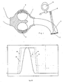
- Fig. 1 shows an example of a charge channel of a reciprocating internal combustion engine with a suction pipe 1, a leading into the working chamber of the internal combustion engine charge channel 2 and a region 3 of the charge channel 2 with two mutually parallel flow paths, in each of which a rotary valve 4, 5 is provided as an additional control valve.
- the connection of the suction tube 1 with the parallel flow paths within the region 3 of the charge channel 2 is not shown in the drawing.
- the drive of the rotary valve within the rotary valve valves 4 and 5 is not shown.
- the rotary valves of the rotary slide valves 4 and 5 can be driven by the number of revolutions of the camshaft 6 acting on a main valve 7 controlling the working chamber of the internal combustion engine through the crankshaft of the internal combustion engine.
- Denoted by 7 main valve is an inlet valve for the associated working space of the internal combustion engine in which oscillates in a piston engine, a piston.
- the rotary valve of the rotary valves 4, 5 can rotate against each other and with respect to the phase position of the camshaft 6 out of phase, including conventional, known per se phase shifting devices are to be turned into the drive.
- the camshaft 6 acts on the main valve 7 via, for example, a lever 8.
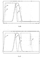
- FIG. 2 each show schematically an intake valve (V) as a function of the crankshaft rotation angle of an internal combustion engine and each of the opening and closing times for the two rotary valves (4 ⁇ , 5 ⁇ , 4S, 5S) for an associated engine cylinder as a working space.
- V intake valve
- 4 ⁇ , 5 ⁇ , 4S, 5S the two rotary valves (4 ⁇ , 5 ⁇ , 4S, 5S) for an associated engine cylinder as a working space.
- the representation is in each case such that the numbers entered on the ordinate 1 denote fully opened and 0 closed cross sections.
- the one in the diagram in Fig. 2A illustrated operating point corresponds to a functionless state of the rotary valves 4, 5 formed as additional control valves.
- Functionless state of the rotary valve 4, 5 as additional control valves means that a rotation of the rotary valve takes place, through which a flow state within the charge channel 2 is present as it would be given even with completely missing additional control valves.
- Such a possible behavior of the additional control valves according to the invention is a particular advantage of the invention.
- the Fig. 2B shows a state in which is adjusted by phase adjustment of the rotary valve 4, 5 with respect to the camshaft 6 early on an operating mode early inlet closing (FES), in which the amount of charge without throttle only about the closing times of the rotary valve valves 4, 5 is set.
- FES early inlet closing
- a further increase in torque can be made possible by briefly interrupting the suction process, as it is in Fig. 2C is shown.
- the obstruction of the flow creates combustion side vacuum and intake manifold side back pressure, which together when reopening a higher cylinder, that is working space charge causes, as a suction with no optimized closing point for the intake valve, comparable to the effect of an air cycle valve (LTV).
- Fig. 2D schematically shows the open and closed times for the operation late-intake-open (SE ⁇ ).
- Fig. 3 Registered rotary valve of the rotary valve valves rotate at half camshaft speed and are independent of each other with respect to the camshaft 6 phase-adjustable.
- Fig. 4A shows a charge control diagram for a clocked suction with additional closing after the first inflow.
- Fig. 4C shows a combination of SE ⁇ and a clocked suction process.
- any inlet opening times and operating modes can be realized. Improvements are possible in the various modes of reciprocating engines, such as two- and four-stroke internal combustion engines, gasoline, diesel, gas, Miller, Atkinson, HCCI, nailsaugender or charged operation.
Landscapes
- Engineering & Computer Science (AREA)
- Chemical & Material Sciences (AREA)
- Combustion & Propulsion (AREA)
- Mechanical Engineering (AREA)
- General Engineering & Computer Science (AREA)
- Valve Device For Special Equipments (AREA)
- Output Control And Ontrol Of Special Type Engine (AREA)
Claims (3)
- Moteur à mouvement alternatif, notamment moteur à combustion interne à piston alternatif,- comportant une chambre de travail commandée par des soupapes principales (7),- un canal de charge (1) menant à au moins une des soupapes principales (7),- une portion du canal de charge (1) divisée en au moins deux parcours de canal de charge s'étendant parallèlement l'un à l'autre,- et dans chacun des deux parcours de canal de charge s'étendant parallèlement l'un à l'autre au moins une soupape supplémentaire (4, 5) commandant la partie locale du courant volumique de charge,caractérisée par les caractéristiques- les soupapes supplémentaires sont réalisées comme des soupapes rotatives (4, 5, 9) entrant en rotation unidirectionnellement lors du fonctionnement du moteur,- les courants de débit volumique des soupapes principales et supplémentaire (7; 4, 5, 9)d'une part ainsi que les soupapes supplémentaires (4, 5, 9) les unes sous les autres d'autre part peuvent être harmonisées de manière variable les unes aux autres par décalage de phase du mouvement de rotation des soupapes rotatives (4, 5, 9),- au moins dans un des parcours s'étendant parallèlement du canal de charge (2), au moins deux soupapes rotatives (4, 9) branchées en série sont prévues.
- Dispositif selon la revendication 1,
caractérisé en ce que
les soupapes rotatives (4, 5, 9) entrent en rotation de manière synchrone au mouvement du piston. - Dispositif selon une des revendications précédentes,
caractérisé en ce que
le vilebrequin du moteur à piston alternatif des soupapes rotatives (4, 5, 9) sert de source d'entraînement.
Applications Claiming Priority (3)
| Application Number | Priority Date | Filing Date | Title |
|---|---|---|---|
| DE10252208 | 2002-11-09 | ||
| DE10252208A DE10252208A1 (de) | 2002-11-09 | 2002-11-09 | Kolbenmaschine, insbesondere Hubkolbenverbrennungsmotor mit zusätzlicher Ladungssteuerung |
| PCT/DE2003/003605 WO2004044404A1 (fr) | 2002-11-09 | 2003-10-29 | Machine a piston, notamment moteur a piston alternatif a combustion interne dote d'une commande supplementaire de charge |
Publications (2)
| Publication Number | Publication Date |
|---|---|
| EP1546523A1 EP1546523A1 (fr) | 2005-06-29 |
| EP1546523B1 true EP1546523B1 (fr) | 2010-05-19 |
Family
ID=32185418
Family Applications (1)
| Application Number | Title | Priority Date | Filing Date |
|---|---|---|---|
| EP03775093A Expired - Lifetime EP1546523B1 (fr) | 2002-11-09 | 2003-10-29 | Machine a piston, notamment moteur a piston alternatif a combustion interne dote d'une commande supplementaire de charge |
Country Status (4)
| Country | Link |
|---|---|
| US (1) | US20050139192A1 (fr) |
| EP (1) | EP1546523B1 (fr) |
| DE (2) | DE10252208A1 (fr) |
| WO (1) | WO2004044404A1 (fr) |
Families Citing this family (6)
| Publication number | Priority date | Publication date | Assignee | Title |
|---|---|---|---|---|
| DE20213365U1 (de) * | 2002-08-30 | 2004-01-15 | Cameron Gmbh | Drosselvorrichtung |
| US6712040B1 (en) * | 2003-01-21 | 2004-03-30 | John Giffin | Variable throttle valve |
| DE102004044140A1 (de) * | 2004-09-13 | 2006-03-30 | Robert Bosch Gmbh | Impulslader im Ansaugtrakt einer Verbrennungskraftmaschine |
| DE102006015589A1 (de) * | 2006-03-31 | 2007-10-04 | Mahle International Gmbh | Frischgasanlage und Betriebsverfahren für einen Kolbenmotor |
| US7401590B2 (en) * | 2006-10-09 | 2008-07-22 | Harley-Davidson Motor Company Group, Inc. | Active air intake for an engine |
| DE102013215764A1 (de) | 2013-08-09 | 2015-02-12 | Volkswagen Aktiengesellschaft | Hubkolbenbrennkraftmaschine sowie Verfahren zur Steuerung der Einlassseite einer Hubkolbenbrennkraftmaschine |
Family Cites Families (21)
| Publication number | Priority date | Publication date | Assignee | Title |
|---|---|---|---|---|
| US2904025A (en) * | 1953-03-26 | 1959-09-15 | Daimler Benz Ag | Internal combustion piston engine |
| GB986331A (en) * | 1962-10-04 | 1965-03-17 | Ricardo & Co Engineers | Internal combustion engines of the vaporised charge spark ignition type |
| US3811418A (en) * | 1971-05-03 | 1974-05-21 | Aisin Seiki | Vehicle speed limiting device |
| DE2621362A1 (de) * | 1976-05-14 | 1977-11-24 | Daimler Benz Ag | Lastregelung fuer gemischverdichtende brennkraftmaschinen mit ventilsteuerung |
| US4333429A (en) * | 1978-06-15 | 1982-06-08 | Honda Giken Kogyo Kabushiki Kaisha | Internal combustion engine |
| DE2938118A1 (de) * | 1979-09-20 | 1981-04-09 | Volkswagenwerk Ag, 3180 Wolfsburg | Regeleinrichtung fuer gemischverdichtende kolbenbrennkraftmaschinen |
| JPS6032352Y2 (ja) * | 1980-06-05 | 1985-09-27 | マツダ株式会社 | 過給機付エンジンの吸気装置 |
| GB2100797B (en) * | 1981-06-24 | 1985-10-09 | Suzuki Motor Co | Duplex carburetor and intake system for internal combustion engines |
| JPS58101238A (ja) * | 1981-12-11 | 1983-06-16 | Mazda Motor Corp | 過給機付エンジンの吸気装置 |
| JPS59208122A (ja) * | 1983-05-12 | 1984-11-26 | Fuji Heavy Ind Ltd | 内燃機関の複式吸気装置 |
| US4738233A (en) * | 1985-02-25 | 1988-04-19 | Mazda Motor Corporation | Intake system for internal combustion engines |
| JPS6258016A (ja) * | 1985-09-06 | 1987-03-13 | Kanesaka Gijutsu Kenkyusho:Kk | エンジンの吸気装置 |
| DE3737820C2 (de) * | 1987-11-06 | 1994-09-22 | Schatz Oskar | Verfahren zum Betrieb eines Verbrennungsmotors und Verbrennungsmotor zur Durchführung des Verfahrens |
| SE467268B (sv) | 1990-05-30 | 1992-06-22 | Volvo Ab | Foerbraenningsmotor med troeghetsuppladdning |
| US5105784A (en) * | 1991-04-08 | 1992-04-21 | General Motors Corporation | Rotary valve and system for duration and phase control |
| JPH07189875A (ja) * | 1993-12-28 | 1995-07-28 | Yamaha Motor Co Ltd | 2サイクルエンジンの燃料噴射装置 |
| GB2319295A (en) * | 1996-11-12 | 1998-05-20 | Ford Motor Co | Mode control for lean burn engines |
| US6391108B2 (en) | 1997-12-12 | 2002-05-21 | Canon Kabushiki Kaisha | Liquid phase growth method of silicon crystal, method of producing solar cell, and liquid phase growth apparatus |
| DE19830575A1 (de) * | 1998-07-08 | 2000-01-13 | Nonox B V | Ladungssteuervorrichtung für eine sowie Verfahren zum Steuern des Betriebs einer Hubkolbenbrennkraftmaschine |
| US6189505B1 (en) * | 1998-09-09 | 2001-02-20 | Dennis Reid | Disc type throttle stop |
| DE10133942A1 (de) * | 2000-07-14 | 2002-01-24 | Schatz Thermo Engineering | Verfahren zur Steuerung der Brennluftzufuhr eines Verbrennungsmotors und Zusatzventilanordnung zur Durchführung des Verfahrens |
-
2002
- 2002-11-09 DE DE10252208A patent/DE10252208A1/de not_active Withdrawn
-
2003
- 2003-10-29 US US10/511,219 patent/US20050139192A1/en not_active Abandoned
- 2003-10-29 DE DE50312726T patent/DE50312726D1/de not_active Expired - Lifetime
- 2003-10-29 EP EP03775093A patent/EP1546523B1/fr not_active Expired - Lifetime
- 2003-10-29 WO PCT/DE2003/003605 patent/WO2004044404A1/fr not_active Ceased
Also Published As
| Publication number | Publication date |
|---|---|
| DE50312726D1 (de) | 2010-07-01 |
| EP1546523A1 (fr) | 2005-06-29 |
| DE10252208A1 (de) | 2004-05-27 |
| WO2004044404A1 (fr) | 2004-05-27 |
| US20050139192A1 (en) | 2005-06-30 |
Similar Documents
| Publication | Publication Date | Title |
|---|---|---|
| EP1236875B1 (fr) | Méthode de réglage du fonctionnement d'un moteur à combustion interne et utilisation d'un dispositif de réglage de charge dans cette méthode | |
| EP2208875B1 (fr) | Dispositif de soupape et moteur à combustion interne. | |
| EP3610147B1 (fr) | Procédé pour faire fonctionner un moteur à combustion interne et moteur à combustion interne | |
| EP0141165A2 (fr) | Dispositif de commande d'admission et d'échappement pour moteurs à combustion interne | |
| EP3464857A1 (fr) | Procédé de fonctionnement d'un moteur à combustion interne et moteur à combustion interne | |
| WO2008017605A1 (fr) | Moteur à combustion | |
| EP2118454B1 (fr) | dispositif de commande de soupape pour moteur à combustion interne à piston | |
| DE102004008350A1 (de) | Motorventilbetätigungssystem | |
| WO2009030694A2 (fr) | Moteur à piston | |
| DE3737820C2 (de) | Verfahren zum Betrieb eines Verbrennungsmotors und Verbrennungsmotor zur Durchführung des Verfahrens | |
| EP1546523B1 (fr) | Machine a piston, notamment moteur a piston alternatif a combustion interne dote d'une commande supplementaire de charge | |
| DE4111153A1 (de) | Einlasssteuerung fuer verbrennungskraftmaschinen | |
| DE102011106394A1 (de) | Brennkraftmaschine | |
| EP1306527B1 (fr) | Moteur diesel à rapport de compression variable | |
| DE102008036494A1 (de) | Brennkraftmaschine und zugehöriges Betriebsverfahren | |
| DE102004005518A1 (de) | Verfahren zum Steuern des Betriebes einer aufgeladenen Kolbenbrennkraftmaschine sowie Kolbenbrennkraftmaschine | |
| DE4341945A1 (de) | Hybridgesteuerter Viertakt-Ottomotor | |
| EP2976512A1 (fr) | Moteur à combustion interne et procédé servant à faire fonctionner un moteur à combustion interne de ce type | |
| WO2006042785A1 (fr) | Procede pour faire fonctionner un moteur a combustion interne | |
| DE102010045893A1 (de) | Kraftfahrzeugbrennkraftmaschinenvorrichtung | |
| DE19731974A1 (de) | Hubkolbenbrennkraftmaschine | |
| DE10359058A1 (de) | Gaswechselventilvorrichtung und Verfahren zur Betreibung derselben | |
| EP2990634A1 (fr) | Dispositif de recirculation des gaz d'echappement pour un moteur a combustion interne | |
| DE10308101A1 (de) | Motormanagement-System und Verfahren zur Einstellung des Drehwinkels einer Nockenwelle gegenüber dem Drehwinkel einer Kurbelwelle eines Kraftfahrzeugs | |
| DE4227261A1 (de) | Vorrichtung zur Erhöhung des Füllungsgrades von Saugmotoren |
Legal Events
| Date | Code | Title | Description |
|---|---|---|---|
| PUAI | Public reference made under article 153(3) epc to a published international application that has entered the european phase |
Free format text: ORIGINAL CODE: 0009012 |
|
| 17P | Request for examination filed |
Effective date: 20040325 |
|
| AK | Designated contracting states |
Kind code of ref document: A1 Designated state(s): AT BE BG CH CY CZ DE DK EE ES FI FR GB GR HU IE IT LI LU MC NL PT RO SE SI SK TR |
|
| RBV | Designated contracting states (corrected) |
Designated state(s): AT BE BG CH CY CZ DE DK EE ES FI FR GB GR HU IE IT LI LU MC NL PT RO SE SI SK TR |
|
| RBV | Designated contracting states (corrected) |
Designated state(s): DE FR GB IT SE |
|
| GRAP | Despatch of communication of intention to grant a patent |
Free format text: ORIGINAL CODE: EPIDOSNIGR1 |
|
| GRAS | Grant fee paid |
Free format text: ORIGINAL CODE: EPIDOSNIGR3 |
|
| GRAA | (expected) grant |
Free format text: ORIGINAL CODE: 0009210 |
|
| AK | Designated contracting states |
Kind code of ref document: B1 Designated state(s): DE FR GB IT SE |
|
| REG | Reference to a national code |
Ref country code: GB Ref legal event code: FG4D Free format text: NOT ENGLISH |
|
| REF | Corresponds to: |
Ref document number: 50312726 Country of ref document: DE Date of ref document: 20100701 Kind code of ref document: P |
|
| REG | Reference to a national code |
Ref country code: SE Ref legal event code: TRGR |
|
| PLBE | No opposition filed within time limit |
Free format text: ORIGINAL CODE: 0009261 |
|
| STAA | Information on the status of an ep patent application or granted ep patent |
Free format text: STATUS: NO OPPOSITION FILED WITHIN TIME LIMIT |
|
| 26N | No opposition filed |
Effective date: 20110222 |
|
| REG | Reference to a national code |
Ref country code: DE Ref legal event code: R097 Ref document number: 50312726 Country of ref document: DE Effective date: 20110221 |
|
| REG | Reference to a national code |
Ref country code: FR Ref legal event code: PLFP Year of fee payment: 13 |
|
| REG | Reference to a national code |
Ref country code: FR Ref legal event code: PLFP Year of fee payment: 14 |
|
| REG | Reference to a national code |
Ref country code: FR Ref legal event code: PLFP Year of fee payment: 15 |
|
| REG | Reference to a national code |
Ref country code: FR Ref legal event code: PLFP Year of fee payment: 16 |
|
| PGFP | Annual fee paid to national office [announced via postgrant information from national office to epo] |
Ref country code: SE Payment date: 20181029 Year of fee payment: 16 |
|
| PGFP | Annual fee paid to national office [announced via postgrant information from national office to epo] |
Ref country code: GB Payment date: 20181031 Year of fee payment: 16 Ref country code: FR Payment date: 20181030 Year of fee payment: 16 Ref country code: IT Payment date: 20181024 Year of fee payment: 16 |
|
| PGFP | Annual fee paid to national office [announced via postgrant information from national office to epo] |
Ref country code: DE Payment date: 20181228 Year of fee payment: 16 |
|
| REG | Reference to a national code |
Ref country code: DE Ref legal event code: R119 Ref document number: 50312726 Country of ref document: DE |
|
| PG25 | Lapsed in a contracting state [announced via postgrant information from national office to epo] |
Ref country code: DE Free format text: LAPSE BECAUSE OF NON-PAYMENT OF DUE FEES Effective date: 20200501 |
|
| PG25 | Lapsed in a contracting state [announced via postgrant information from national office to epo] |
Ref country code: SE Free format text: LAPSE BECAUSE OF NON-PAYMENT OF DUE FEES Effective date: 20191030 |
|
| GBPC | Gb: european patent ceased through non-payment of renewal fee |
Effective date: 20191029 |
|
| PG25 | Lapsed in a contracting state [announced via postgrant information from national office to epo] |
Ref country code: IT Free format text: LAPSE BECAUSE OF NON-PAYMENT OF DUE FEES Effective date: 20191029 Ref country code: FR Free format text: LAPSE BECAUSE OF NON-PAYMENT OF DUE FEES Effective date: 20191031 Ref country code: GB Free format text: LAPSE BECAUSE OF NON-PAYMENT OF DUE FEES Effective date: 20191029 |