EP1546576B1 - Unite d'entrainement de boite surface de butee inclinee - Google Patents
Unite d'entrainement de boite surface de butee inclinee Download PDFInfo
- Publication number
- EP1546576B1 EP1546576B1 EP03720273A EP03720273A EP1546576B1 EP 1546576 B1 EP1546576 B1 EP 1546576B1 EP 03720273 A EP03720273 A EP 03720273A EP 03720273 A EP03720273 A EP 03720273A EP 1546576 B1 EP1546576 B1 EP 1546576B1
- Authority
- EP
- European Patent Office
- Prior art keywords
- component
- drive unit
- shaft
- gearing
- stop
- Prior art date
- Legal status (The legal status is an assumption and is not a legal conclusion. Google has not performed a legal analysis and makes no representation as to the accuracy of the status listed.)
- Expired - Lifetime
Links
- 239000000470 constituent Substances 0.000 claims 1
- 230000013011 mating Effects 0.000 claims 1
- 230000005540 biological transmission Effects 0.000 description 14
- 238000006073 displacement reaction Methods 0.000 description 10
- 230000002349 favourable effect Effects 0.000 description 3
- 239000000463 material Substances 0.000 description 3
- 238000004519 manufacturing process Methods 0.000 description 2
- 230000000149 penetrating effect Effects 0.000 description 2
- 229910000831 Steel Inorganic materials 0.000 description 1
- 230000001133 acceleration Effects 0.000 description 1
- 230000001419 dependent effect Effects 0.000 description 1
- 238000007598 dipping method Methods 0.000 description 1
- 238000003780 insertion Methods 0.000 description 1
- 230000037431 insertion Effects 0.000 description 1
- 230000007774 longterm Effects 0.000 description 1
- 238000000465 moulding Methods 0.000 description 1
- 238000004080 punching Methods 0.000 description 1
- 230000000717 retained effect Effects 0.000 description 1
- 230000035939 shock Effects 0.000 description 1
- 239000010959 steel Substances 0.000 description 1
Images



Classifications
-
- F—MECHANICAL ENGINEERING; LIGHTING; HEATING; WEAPONS; BLASTING
- F16—ENGINEERING ELEMENTS AND UNITS; GENERAL MEASURES FOR PRODUCING AND MAINTAINING EFFECTIVE FUNCTIONING OF MACHINES OR INSTALLATIONS; THERMAL INSULATION IN GENERAL
- F16H—GEARING
- F16H57/00—General details of gearing
- F16H57/02—Gearboxes; Mounting gearing therein
- F16H57/021—Shaft support structures, e.g. partition walls, bearing eyes, casing walls or covers with bearings
-
- F—MECHANICAL ENGINEERING; LIGHTING; HEATING; WEAPONS; BLASTING
- F16—ENGINEERING ELEMENTS AND UNITS; GENERAL MEASURES FOR PRODUCING AND MAINTAINING EFFECTIVE FUNCTIONING OF MACHINES OR INSTALLATIONS; THERMAL INSULATION IN GENERAL
- F16H—GEARING
- F16H1/00—Toothed gearings for conveying rotary motion
- F16H1/02—Toothed gearings for conveying rotary motion without gears having orbital motion
- F16H1/04—Toothed gearings for conveying rotary motion without gears having orbital motion involving only two intermeshing members
- F16H1/12—Toothed gearings for conveying rotary motion without gears having orbital motion involving only two intermeshing members with non-parallel axes
- F16H1/16—Toothed gearings for conveying rotary motion without gears having orbital motion involving only two intermeshing members with non-parallel axes comprising worm and worm-wheel
-
- F—MECHANICAL ENGINEERING; LIGHTING; HEATING; WEAPONS; BLASTING
- F16—ENGINEERING ELEMENTS AND UNITS; GENERAL MEASURES FOR PRODUCING AND MAINTAINING EFFECTIVE FUNCTIONING OF MACHINES OR INSTALLATIONS; THERMAL INSULATION IN GENERAL
- F16C—SHAFTS; FLEXIBLE SHAFTS; ELEMENTS OR CRANKSHAFT MECHANISMS; ROTARY BODIES OTHER THAN GEARING ELEMENTS; BEARINGS
- F16C17/00—Sliding-contact bearings for exclusively rotary movement
- F16C17/04—Sliding-contact bearings for exclusively rotary movement for axial load only
- F16C17/08—Sliding-contact bearings for exclusively rotary movement for axial load only for supporting the end face of a shaft or other member, e.g. footstep bearings
-
- H—ELECTRICITY
- H02—GENERATION; CONVERSION OR DISTRIBUTION OF ELECTRIC POWER
- H02K—DYNAMO-ELECTRIC MACHINES
- H02K7/00—Arrangements for handling mechanical energy structurally associated with dynamo-electric machines, e.g. structural association with mechanical driving motors or auxiliary dynamo-electric machines
- H02K7/08—Structural association with bearings
- H02K7/081—Structural association with bearings specially adapted for worm gear drives
-
- F—MECHANICAL ENGINEERING; LIGHTING; HEATING; WEAPONS; BLASTING
- F16—ENGINEERING ELEMENTS AND UNITS; GENERAL MEASURES FOR PRODUCING AND MAINTAINING EFFECTIVE FUNCTIONING OF MACHINES OR INSTALLATIONS; THERMAL INSULATION IN GENERAL
- F16C—SHAFTS; FLEXIBLE SHAFTS; ELEMENTS OR CRANKSHAFT MECHANISMS; ROTARY BODIES OTHER THAN GEARING ELEMENTS; BEARINGS
- F16C2361/00—Apparatus or articles in engineering in general
- F16C2361/61—Toothed gear systems, e.g. support of pinion shafts
-
- F—MECHANICAL ENGINEERING; LIGHTING; HEATING; WEAPONS; BLASTING
- F16—ENGINEERING ELEMENTS AND UNITS; GENERAL MEASURES FOR PRODUCING AND MAINTAINING EFFECTIVE FUNCTIONING OF MACHINES OR INSTALLATIONS; THERMAL INSULATION IN GENERAL
- F16H—GEARING
- F16H57/00—General details of gearing
- F16H57/02—Gearboxes; Mounting gearing therein
- F16H57/021—Shaft support structures, e.g. partition walls, bearing eyes, casing walls or covers with bearings
- F16H57/022—Adjustment of gear shafts or bearings
- F16H2057/0221—Axial adjustment
-
- F—MECHANICAL ENGINEERING; LIGHTING; HEATING; WEAPONS; BLASTING
- F16—ENGINEERING ELEMENTS AND UNITS; GENERAL MEASURES FOR PRODUCING AND MAINTAINING EFFECTIVE FUNCTIONING OF MACHINES OR INSTALLATIONS; THERMAL INSULATION IN GENERAL
- F16H—GEARING
- F16H57/00—General details of gearing
- F16H57/12—Arrangements for adjusting or for taking-up backlash not provided for elsewhere
- F16H2057/126—Self-adjusting during operation, e.g. by a spring
- F16H2057/127—Self-adjusting during operation, e.g. by a spring using springs
-
- Y—GENERAL TAGGING OF NEW TECHNOLOGICAL DEVELOPMENTS; GENERAL TAGGING OF CROSS-SECTIONAL TECHNOLOGIES SPANNING OVER SEVERAL SECTIONS OF THE IPC; TECHNICAL SUBJECTS COVERED BY FORMER USPC CROSS-REFERENCE ART COLLECTIONS [XRACs] AND DIGESTS
- Y10—TECHNICAL SUBJECTS COVERED BY FORMER USPC
- Y10T—TECHNICAL SUBJECTS COVERED BY FORMER US CLASSIFICATION
- Y10T74/00—Machine element or mechanism
- Y10T74/18—Mechanical movements
- Y10T74/18568—Reciprocating or oscillating to or from alternating rotary
- Y10T74/18576—Reciprocating or oscillating to or from alternating rotary including screw and nut
- Y10T74/18728—Backlash
-
- Y—GENERAL TAGGING OF NEW TECHNOLOGICAL DEVELOPMENTS; GENERAL TAGGING OF CROSS-SECTIONAL TECHNOLOGIES SPANNING OVER SEVERAL SECTIONS OF THE IPC; TECHNICAL SUBJECTS COVERED BY FORMER USPC CROSS-REFERENCE ART COLLECTIONS [XRACs] AND DIGESTS
- Y10—TECHNICAL SUBJECTS COVERED BY FORMER USPC
- Y10T—TECHNICAL SUBJECTS COVERED BY FORMER US CLASSIFICATION
- Y10T74/00—Machine element or mechanism
- Y10T74/19—Gearing
- Y10T74/19623—Backlash take-up
-
- Y—GENERAL TAGGING OF NEW TECHNOLOGICAL DEVELOPMENTS; GENERAL TAGGING OF CROSS-SECTIONAL TECHNOLOGIES SPANNING OVER SEVERAL SECTIONS OF THE IPC; TECHNICAL SUBJECTS COVERED BY FORMER USPC CROSS-REFERENCE ART COLLECTIONS [XRACs] AND DIGESTS
- Y10—TECHNICAL SUBJECTS COVERED BY FORMER USPC
- Y10T—TECHNICAL SUBJECTS COVERED BY FORMER US CLASSIFICATION
- Y10T74/00—Machine element or mechanism
- Y10T74/19—Gearing
- Y10T74/19642—Directly cooperating gears
- Y10T74/19698—Spiral
- Y10T74/19828—Worm
Definitions
- the invention relates to a transmission drive unit, in particular for adjusting moving parts in the motor vehicle, according to the preamble of the main claim.
- a drive device for a windscreen wiper system of a motor vehicle which has a housing and an armature shaft rotatably mounted therein with a worm.
- a wedge slide is moved radially to the armature shaft to compensate for the axial play of the armature shaft.
- the displacement force of the wedge slide is applied by a biased spring element which presses the wedge slide radially against a stop of the armature shaft, whereby it is displaced axially until the axial play.
- DE-A-23 12 395 also shows an electric drive device in which an axial force can be generated on the armature shaft by means of a radially displaceable wedge.
- the wedge is here also adjusted radially by means of a spiral spring, whereby axial shocks are damped on the armature shaft.
- a worm gear has become known in which a shaft end is supported on a multi-part wedge-shaped insert part.
- the wedge-shaped insert part has a supporting part, which rests against the housing wall and a sliding wedge with form-fitting interlocking contours.
- the wedge is hereby pressed radially by a spiral spring to the shaft axis.
- the transmission drive unit with the features of the main claim has the advantage that an axial force generating device is arranged such that whose coefficient of friction prevents a radial retreat of a component which compensates for axial play.
- the geometry, the surfaces and the materials of the Axialkrafter Wegungs are chosen so that the coefficient of friction between an inclined by an inclination angle to the perpendicular of the shaft stop surface and the surface of a component is greater than the tangent of the inclination angle.
- the component is displaced radially towards the shaft as soon as the shaft has a longitudinal play. A pushing back of the component is prevented by the friction condition.
- an elastic element used to move the component does not have to absorb high restoring forces that are introduced by the shaft onto the component.
- the elasticity of the elastic element is therefore retained over its entire service life, whereby the longitudinal play of the shaft over the entire life is reliably eliminated.
- the wavelength play is eliminated without having to be measured beforehand this longitudinal clearance during assembly of the device in order to compensate for this example by means of selectively mounted shims. This reduces the number of stations in the assembly line and simplifies the mounting device.
- the axial force generating device can be manufactured on a modular basis, so that it is compatible with many different drive units.
- the coefficient of friction between the surface of the component and the inclined abutment surface is increased particularly favorable by forming a profile on one of the two friction surfaces. If, for example, a sawtooth-like profile is formed on at least one of the surfaces, then the component can be moved radially back onto the shaft with little force, but can be moved back radially only with significantly greater expenditure of force.
- a structured surface therefore results in that the elastic element for the displacement of the component is not excessively loaded.
- the elastic element can thus radially nachschieben the component over the entire life of the device to eliminate the axial play occurring.
- one of the two abutment surfaces or the component can have a stepped step-shaped surface, in which the "tread surfaces" are oriented approximately perpendicular to the longitudinal axis of the shaft.
- the shaft is supported on a radially symmetrical surface, whereby the shaft remains centered very precisely radially symmetrically even under load.
- the conical surface serves to ensure that the at least one component can be displaced uniformly from all sides at the same time to the shaft axis.
- one of the stop surfaces is designed as a part together with the component. As a result, no additional starting elements are needed, whereby the assembly cost is reduced.
- the component can also be used particularly favorably for a penetrating shaft.
- the component is not arranged on the end face of a shaft, but engages around the shaft and is supported, for example, on a collar made of this.
- Such U-shaped component is also advantageous for the application of a shaft which is mounted with a starting sleeve, because the U-shaped component engages around the starting sleeve in order to reduce the overall length of the drive.
- the component is annular and radially elastically stretchable. As a result, this component slides due to its bias in the gap between the two stop surfaces, so that no additional elastic element is necessary, which acts on the component with a displacement force. If such a component designed as an elastic ring element is coupled to a step-shaped abutment surface which is designed as a cone, then the spring ring contracts to compensate for the axial play increased by signs of wear. It is not necessary that the elastic ring element is supported on the housing.
- the component can easily have two offset, separate wedge surfaces, which are connected to each other via a surface which is perpendicular to the shaft axis.
- the wedge-shaped component can be pushed radially against the shaft over time, the height of the entire drive device is reduced by reducing the overall height of the component.
- the axial forces of the shaft are favorably absorbed very uniformly over a large diameter of the stop surface.
- the axial force generating device according to the invention can be arranged both on the front side or on a collar of the shaft, so that a high variance is ensured for different embodiments of the transmission drive unit.
- the component is constantly tracked by a displacement force which is applied by a prestressed elastic element.
- the stored energy of the spring element causes such a self-adjusting axial play compensation over the entire life of the transmission drive unit presses the component with sufficient force against the shaft.
- the pre-assembled elastic element is biased directly to the fastening of the cover of the transmission housing. Due to the radial mounting of the elastic element no further auxiliary tools are necessary for this purpose.
- the elastic element is embodied either as an integral part of the cover of the gearbox housing or of the component, since in this way the elastic element during assembly of the component or of the component Transmission housing cover is positioned directly and precisely the assembly is simplified by reducing the components.
- the component is formed integrally with the elastic element, this can be formed, for example, from a leaf spring.
- the wedge-shaped leaf spring In order for the wedge-shaped leaf spring to be able to absorb higher axial forces at its end faces, it is designed to be corrugated in the region of the acting axial force for reasons of stability.
- the free ends of the leaf spring support the component against the transmission housing in order to track the component perpendicular to the longitudinal axis of the shaft.
- the component together with the elastic element is very inexpensive to manufacture as a bending-punching part.
- FIG. 1 shows a transmission drive unit 10 according to the invention in section, in which a not-shown electric motor 12 via a worm gear 14 drives a spindle 16 as a shaft 18 which projects from the gear housing 15 of the worm gear 14.
- a worm wheel 20 is formed, which has a collar 22.
- This collar 22 forms a first contact surface 24, which is supported on a counter-contact surface 26 of a thrust washer 28 which bears against the gear housing 15.
- the mounted along a longitudinal axis 30 shaft 18 is supported with an end face 32 at a further end-side thrust element 34, which has a stop surface 35 on the side facing away from the end face 32 side.
- a further abutment surface 36 is formed, which is inclined by an angle of inclination 40 relative to a plane perpendicular to the longitudinal axis 30 plane 42.
- a component 44 is arranged in a gap 64, which is displaceable perpendicular to the longitudinal axis 30 for eliminating the wavelength play.
- the component 44 is wedge-shaped, so that the wedge angle corresponds to the angle of inclination 40 of the inclined abutment surface 36.
- an elastic element 48 is arranged, which presses the component 44 radially against the longitudinal axis 30 in the gap 64 inside.
- the thrust element 34 is in this case formed integrally with the component 44, so that the abutment surface 35 is formed directly from the end face 32 of the shaft 32.
- an axial force 50 acts along the longitudinal axis 30 on the component 44 which transmits this axial force 50 on the abutment surface 36.
- the downhill force 54 counteracts a frictional force 56, which is generated when moving the component 44 relative to the abutment surface 36.
- the friction force 56 is greater than the maximum occurring downgrade force 54 at maximum axial load of the shaft 18. From this mathematically results in that the tangent of the inclination angle 40 is smaller than the friction coefficient corresponding to the friction force 56.
- the friction coefficient is determined essentially by the selection of materials and the surface properties of the mutually displaceable surfaces.
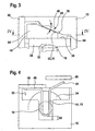
- FIG. 3 shows a component 44 in which the coefficient of friction is increased by a sawtooth profile 60 on a friction surface 62 between the component 44 and the oblique stop surface 36.
- the sawtooth-like profile 60 is integrally formed on the component, but may just as well be arranged on the inclined contact surface 36 of the housing 15 or the abutment surface 35.
- the sawtooth profile 60 is shaped so that the wedge-shaped component 44 can be displaced with a lower displacement force 58 of the elastic element 48 perpendicular to the shaft 18, as this is pressed back by the slope force 54.
- the component 44 is due to the spring force 58, with which the elastic member 48 is supported relative to the housing part 46, further in the gap 64 between the abutment surface 35 of the thrust washer 34 and the oblique Sliding surface 36 of the housing 15 pushed into it.
- Figure 4 shows another embodiment in a representation according to the section IV-IV in Figure 3.
- the component 44 is U-shaped, in which case both legs with respect to the end face 32 of the shaft 18 are arranged.
- the elastic element 48 is integrally formed as an integral part of the component 44, wherein the one-piece component 44 is punched out of a steel sheet, for example.
- the component 44 of Figure 4 is shown again in the side view and in plan view, the friction surface 62 of the component 44 is disposed at the same angle of inclination 40 relative to the plane 42 as the korespend Schl stop surface 36 of the housing 15.
- the inclination angle 40 and the total length of the component 44 set a maximum stroke 70 by which the maximum wavelength play can be compensated.
- a maximum spring travel 72 is shown, by which the elastic member 48 can be biased by the housing part 46 during assembly. From this route 73 results in the force 58, with which the elastic element 48 presses the component 44 into the gap 64.
- FIGS. 6a and 6b show a variation of the component 44 from FIGS. 5a and 5b, wherein here a sawtooth profile 60 is integrally formed on the friction surface 62 of the wedge-shaped component 44.
- the U-shaped component 44 is in this case wave-shaped, as can be seen in FIG. 6 b, in order to be able to absorb higher axial forces 50.
- the maximum spring travel 72 of the elastic element 48 is larger in this example, whereby the component 44 is pressed with a higher force 58 against the longitudinal axis 30.
- FIG. 7 illustrates, as a further exemplary embodiment of a transmission drive unit 10, a dipping spindle motor whose shaft 18 can not be mounted on its end faces 32 at the end of the shaft 18.
- An electric motor 12 drives here via a worm of the armature shaft to a worm wheel 20 which is rotatably mounted on the shaft 18. Since the shaft formed as a spindle 16 18 projects on both sides of the worm wheel 20 from the gear housing 15, the shaft 18 is axially supported axially via two annular stop surfaces 24.
- the worm wheel 20 of the shaft 18 has on one side a collar 22, a Run-on surface 24 forms, which abuts with the stop surface 26 of a thrust washer 28, which in turn is supported on the transmission housing 15. On the axially opposite side of the worm wheel 20, this also has a collar 23, with which the shaft 18 is supported on this side of a thrust washer 34.
- a stop surface 36 which is inclined relative to the plane 42 by the inclination angle 40 is formed in this exemplary embodiment and is penetrated by the shaft 18.
- a wedge-shaped member 44 is inserted perpendicular to the shaft 18 to compensate for the manufacturing and operational axial play between the shaft 18 and housing 15.
- the component 44 has a wedge angle 40 which corresponds to the angle of inclination 40 of the inclined abutment surface 36.
- the component 44 is pressed with a force 58 into the gap 64 between the thrust washer 34 and the abutment surface 36, which is generated by the prestressed elastic element 48.
- the component 44 can not be made flat in this case, as is possible with a bearing of the shaft 18 via the end face 32, but the component 44 is U-shaped or arcuate to engage around the shaft 18.
- FIG. 9a shows A variation of the U-shaped member 44 in Figure 9a and Figure 9b in side and top views.
- the friction surface 62 which is designed here as a smooth surface 63; is divided in the side view into two offset areas, which is connected by a surface 76 which is parallel to the plane 42.
- the korespend Schlierende stop surface 36 has a corresponding stepped wedge profile. In this case, the overall height 78 of the component 44 can be reduced without thereby reducing the angle of inclination 40.
- FIG. 9b shows the component 44 in plan view with the partial friction surfaces 62 and the intermediate surfaces 76, which run parallel to the plane 42.
- the housing 15 - or alternatively also the approximately square thrust washer 34 - must have a correspondingly inclined abutment surface 36 in the region of the U-shaped friction surface 62. It is essential that one of the two stop surfaces 35 or 36 is inclined according to the wedge angle 40 of the component. In a variation, the component is designed as a two-sided wedge and the two abutment surfaces 35, 36 are each inclined by the one angular portion.
- FIGS. 10a to 10c show a further exemplary embodiment in which a shaft 18 is axially mounted on its end face 32 in a starting sleeve 80.
- a shaft 18 is axially mounted on its end face 32 in a starting sleeve 80.
- an annular abutment surface 35 integrally formed, which abuts the arcuately executed, the stop sleeve 80 encompassing member 44.
- the component 44 is supported via the friction surface 62 on the abutment surface 36 inclined by the inclination angle 40.
- the component 44 is again formed in one piece with the elastic element 48, which is supported on a cover 66 of the gear housing 15.
- the one-piece component 44 is similar to FIG. 5a and b manufactured as a leaf spring 45, wherein this is wedge-shaped in particular in the areas 84 in the insertion direction.
- a displacement path 68 is available for the component 44, by which it can be pushed by the spring force 58 of the elastic component 48 into the gap 64.
- Figure 11 shows another embodiment in which the inclined abutment surface 36 is formed as a cone 90.
- the shaft 18 has a collar 23 which rests against an annular thrust washer 34.
- the inclined abutment surface 36 is here not formed as a plane plane, but radially symmetrical as a truncated cone lateral surface 90, which forms the inclination angle 40 with the plane 42.
- the abutment surface 36 is penetrated by the shaft 18, so that this embodiment is also suitable for a penetrating spindle 16.
- the conical abutment surface 36 in this case has a stair-step-shaped profile 91, so that the individual annular surfaces 92 extend approximately parallel to the plane 42.
- an elastic ring member 94 is arranged as a component 44, via which the shaft 18 is supported on the housing 15.
- the elastic ring member 94 consists for example of a mated coil spring 96 which is mounted under pretension in the transmission housing 15 in a rest position 98.
- the annular spring 96 stretches as soon as it is pushed from its rest position 98 into the gap 64 between the two abutment surfaces 36 and 35 and contracts so far until the axial clearance is balanced. If the axial play increases, for example because of wear, the spiral spring 96 can continue to pull radially together in the gap 64.
- the friction condition is that the friction coefficient should be larger than the tangent of the tilt angle 40 the conical surface 36 ensured by the stepped profile.
- the abutment surface 36 formed as a cone 90 has a smooth surface 63, and the component 44 is made at least on the surface of a material which, in conjunction with the surface of the cone 90 results in a high coefficient of friction.
- no separate elastic element 48 is necessary, which is supported on a housing part 46, but by the elastic design of the component 44 as an annular spring 94, the displacement force 58 is applied by the radial bias of the elastic ring member 94.
- the elastic ring element 94 instead of the elastic ring element 94, there are a plurality of wedge-shaped components 44 in the gap 64 between the stepped cone 90 and the abutment surface 35 of the thrust washer 34.
- the components 44 are preferably designed as circular ring segments whose friction surface 62 likewise has stepped annular surfaces Have segments which extend approximately parallel to the annular surfaces 92 of the cone or to the plane 42. These components are pressed by means of elastic elements 48 in the gap 64, which are supported for example either on the gear housing 15.
- an annular spring 96 is arranged around the components 44 on the radial outer surface thereof, which on contracting exerts a radial displacement force 58 on the wedge-shaped, stepped components 44.
- the axial force generating device according to the invention is preferably used in submerged spindle drives, but can also be used for the storage of armature shafts with any output elements or other transmission components. Furthermore, the invention also includes individual features of the embodiments or any combination of the features of different embodiments.
Landscapes
- Engineering & Computer Science (AREA)
- General Engineering & Computer Science (AREA)
- Mechanical Engineering (AREA)
- Power Engineering (AREA)
- Gear Transmission (AREA)
Claims (13)
- Unité d'entraînement de boîte de vitesses (10) - en particulier pour déplacer des pièces mobiles dans un véhicule automobile - comportant un carter de boîte (15) et un arbre (18), positionné dans celui-ci le long d'un axe longitudinal (30), lequel arbre s'appuie sur une face de contrebutée (36) du carter par l'intermédiaire d'une face de butée axiale (35), au moins l'une des faces de butée (35, 36) étant inclinée selon un angle d'inclinaison (40) contre un plan (42) perpendiculaire à l'axe longitudinal (30) pour produire une force axiale, alors qu'un composant (44) coopérant avec au moins l'une des faces de butée (35, 36) est mobile perpendiculairement à l'axe longitudinal (30) le composant (44) étant mobile radialement à l'axe longitudinal (30) au moyen d'un élément élastique précontraint (48), le coefficient de frottement entre au moins une face de butée (35, 36) et le composant (44) étant plus important pour un mouvement destiné à la diminution de la force axiale que la tangente de l'angle d'inclinaison (40),
caractérisé en ce que
l'élément élastique (48) est un constituant intégral du composant (44) qui forme avec celui-ci une pièce découpée flexible. - Unité d'entraînement de boîte de vitesses (10) selon la revendication 1,
caractérisée en ce qu'
au moins l'une des faces de butée (35, 36) et/ou le composant (44) présentent une surface profilée (62) - en particulier un profilé (62) similaire à des dents de scie. - Unité d'entraînement de boîte de vitesses (10) selon l'une quelconque des revendications 1 ou 2,
caractérisée en ce qu'
au moins l'une des faces de butée (35, 36) et/ou le composant (44) présente un profilé (91) similaire à des marches d'escalier. - Unité d'entraînement de boîte de vitesses (10) selon l'une quelconque des revendications 1 à 3,
caractérisée en ce qu'
au moins l'une des faces de butée (35, 36) est conique - en particulier avec des marches d'escalier annulaires (92). - Unité d'entraînement de boîte de vitesses (10) selon l'une quelconque des revendications 1 à 4,
caractérisée en ce que
le composant (44) forme une seule pièce avec l'une des faces de butée (35, 36) - en particulier en tant qu'élément de démarrage (34). - Unité d'entraînement de boîte de vitesses (10) selon l'une quelconque des revendications précédentes,
caractérisée en ce que
le composant (44) a la forme d'un U et enveloppe en particulier l'arbre (18) ou un manchon de démarrage (70) de l'arbre (18). - Unité d'entraînement de boîte de vitesses (10) selon l'une quelconque des revendications précédentes,
caractérisée en ce que
le composant (44) est un élément annulaire élastique (94, 96) qui peut être compressé radialement. - Unité d'entraînement de boîte de vitesses (10) selon l'une quelconque des revendications précédentes,
caractérisée en ce que
le composant (44) est un coin à 2 niveaux. - Unité d'entraînement de boîte de vitesses (10) selon l'une quelconque des revendications précédentes,
caractérisée en ce que
l'arbre (18) présente une face avant (32) et/ou au moins une collerette (22, 23) avec laquelle l'arbre s'appuie contre le carter de boîte (15) par l'intermédiaire du composant (44). - Unité d'entraînement de boîte de vitesses (10) selon l'une quelconque des revendications précédentes,
caractérisée en ce que
l'arbre (18) présente une denture hélicoïdale ou filetée (19) et s'enclenche en particulier dans un filetage intérieur (21) d'un dispositif d'entraînement de broche (10). - Unité d'entraînement de boîte de vitesses (10) selon la revendication 1,
caractérisée en ce que
l'élément élastique (48) s'appuie sur un couvercle (66) du carter de boîte (15). - Unité d'entraînement de boîte de vitesses (10) selon la revendication 1 ou 11,
caractérisée en ce que
l'élément élastique (48) forme une seule pièce avec le couvercle (66). - Unité d'entraînement de boîte de vitesses (10) selon l'une quelconque des revendications 1, 11, ou 12,
caractérisée en ce que
le composant (44) est configuré, avec l'élément élastique (48), en forme de ressort à lame (45) ondulé en forme de coin.
Applications Claiming Priority (3)
| Application Number | Priority Date | Filing Date | Title |
|---|---|---|---|
| DE10245269 | 2002-09-27 | ||
| DE10245269A DE10245269A1 (de) | 2002-09-27 | 2002-09-27 | Getriebe-Antriebseinheit mit geneigter Anschlagsfläche |
| PCT/DE2003/001233 WO2004031613A1 (fr) | 2002-09-27 | 2003-04-11 | Unité d'entraînement de boîte à surface de butée inclinée |
Publications (2)
| Publication Number | Publication Date |
|---|---|
| EP1546576A1 EP1546576A1 (fr) | 2005-06-29 |
| EP1546576B1 true EP1546576B1 (fr) | 2006-11-15 |
Family
ID=31969680
Family Applications (1)
| Application Number | Title | Priority Date | Filing Date |
|---|---|---|---|
| EP03720273A Expired - Lifetime EP1546576B1 (fr) | 2002-09-27 | 2003-04-11 | Unite d'entrainement de boite surface de butee inclinee |
Country Status (6)
| Country | Link |
|---|---|
| US (1) | US7467565B2 (fr) |
| EP (1) | EP1546576B1 (fr) |
| KR (1) | KR101000730B1 (fr) |
| AU (1) | AU2003223916A1 (fr) |
| DE (2) | DE10245269A1 (fr) |
| WO (1) | WO2004031613A1 (fr) |
Cited By (4)
| Publication number | Priority date | Publication date | Assignee | Title |
|---|---|---|---|---|
| DE102018100458A1 (de) | 2018-01-10 | 2019-07-11 | Nidec Motors & Actuators (Germany) Gmbh | Getriebegehäuseeinheit und Getriebeeinheit mit keilförmigem Ausgleichselement zum Axialspielausgleich |
| DE102018126054A1 (de) | 2018-10-19 | 2020-04-23 | Nidec Motors & Actuators (Germany) Gmbh | Ausgleichsanordnung zum Axialspielausgleich und Getriebeeinheit |
| DE102018126055A1 (de) | 2018-10-19 | 2020-04-23 | Nidec Motors & Actuators (Germany) Gmbh | Getriebegehäuseeinheit mit Axialscheibe |
| DE102020105407A1 (de) | 2020-02-28 | 2021-09-02 | Nidec Motors & Actuators (Germany) Gmbh | Getriebegehäuseeinheit mit eingespannter Anlaufscheibe |
Families Citing this family (9)
| Publication number | Priority date | Publication date | Assignee | Title |
|---|---|---|---|---|
| CN101162037B (zh) * | 2006-10-11 | 2011-08-03 | 德昌电机股份有限公司 | 蜗轮传动机构 |
| US7886625B2 (en) * | 2008-11-16 | 2011-02-15 | Hiwin Mikrosystem Corp. | Actuator with self-locking assist device |
| WO2012116892A1 (fr) * | 2011-02-28 | 2012-09-07 | C: Rob Hammerstein Gmbh & Co. Kg | Entraînement de réglage et procédé de fabrication d'un entraînement de réglage |
| DE102012207129A1 (de) * | 2012-04-27 | 2013-10-31 | Robert Bosch Gmbh | Getriebespindel sowie Spindelgetriebe, sowie Verfahren zum Herstellen einer Getriebespindel |
| KR101428302B1 (ko) * | 2012-12-21 | 2014-08-07 | 현대자동차주식회사 | 액티브 에어플랩 장치용 액추에이터 |
| US9464464B2 (en) * | 2013-09-16 | 2016-10-11 | Kiekert Ag | Drive unit |
| CN107701711A (zh) * | 2017-11-18 | 2018-02-16 | 苏州金牛精密机械有限公司 | 一种齿轮间隙调整机构 |
| DE102018219264A1 (de) | 2018-11-12 | 2020-05-14 | Thyssenkrupp Ag | Verstellantrieb für eine Lenksäule und Lenksäule für ein Kraftfahrzeug |
| CN116733943A (zh) * | 2023-05-11 | 2023-09-12 | 恺博(常熟)座椅机械部件有限公司 | 一种齿轮箱轴向间隙补偿结构 |
Family Cites Families (12)
| Publication number | Priority date | Publication date | Assignee | Title |
|---|---|---|---|---|
| DE23024C (de) * | L. GATHMANN in Chicago, III., V. St. A | Getreidebüratmaschine mit Spiralgang und Luftfurchen | ||
| DE563410C (de) * | 1931-09-04 | 1934-02-02 | Graphitwerk Kropfmuehl Akt Ges | Galvanisches Element |
| US3549218A (en) * | 1969-05-02 | 1970-12-22 | Ford Motor Co | End thrust control device for a rotating shaft |
| IT950189B (it) | 1972-03-15 | 1973-06-20 | Magneti Marelli Spa | Dispositivo per guidare e per ri prendere il gioco assiale delle viti dei riduttori a vite senza fine particolarmente per motori duttori di piccola potenza |
| US4212379A (en) * | 1978-03-17 | 1980-07-15 | Zoino Hugo A | Conical clutch |
| DE2928963A1 (de) * | 1979-07-18 | 1981-01-22 | No Sag Drahtfedern Gmbh | Verbindungs- und/oder anschlusselement fuer rahmenteile aus federstahldraht |
| DE59202352D1 (de) * | 1992-03-27 | 1995-06-29 | Siemens Ag | Selbstnachstellende Axialspieleinstellung für eine Rotorwelle. |
| DE19520886C1 (de) | 1995-06-08 | 1996-10-02 | Brose Fahrzeugteile | Schneckengetriebe für eine Verstellvorrichtung in einem Kraftfahrzeug |
| JP4079512B2 (ja) * | 1998-05-25 | 2008-04-23 | デルタ工業株式会社 | 車両用シートの減速装置 |
| DE19854535A1 (de) | 1998-11-26 | 2000-06-15 | Valeo Auto Electric Gmbh | Antriebsvorrichtung, insbesondere für eine Scheibenwischanlage eines Kraftfahrzeugs |
| US6805024B1 (en) * | 2001-10-09 | 2004-10-19 | Valeo Electrical Systems, Inc. | End play restriction wedge |
| US7116025B2 (en) * | 2003-12-22 | 2006-10-03 | Valeo Electric Systems, Inc. | Endplay adjustment system and method |
-
2002
- 2002-09-27 DE DE10245269A patent/DE10245269A1/de not_active Withdrawn
-
2003
- 2003-04-11 AU AU2003223916A patent/AU2003223916A1/en not_active Abandoned
- 2003-04-11 KR KR1020057005169A patent/KR101000730B1/ko not_active Expired - Fee Related
- 2003-04-11 EP EP03720273A patent/EP1546576B1/fr not_active Expired - Lifetime
- 2003-04-11 WO PCT/DE2003/001233 patent/WO2004031613A1/fr not_active Ceased
- 2003-04-11 US US10/529,275 patent/US7467565B2/en not_active Expired - Fee Related
- 2003-04-11 DE DE50305705T patent/DE50305705D1/de not_active Expired - Lifetime
Cited By (9)
| Publication number | Priority date | Publication date | Assignee | Title |
|---|---|---|---|---|
| DE102018100458A1 (de) | 2018-01-10 | 2019-07-11 | Nidec Motors & Actuators (Germany) Gmbh | Getriebegehäuseeinheit und Getriebeeinheit mit keilförmigem Ausgleichselement zum Axialspielausgleich |
| DE102018100458B4 (de) | 2018-01-10 | 2019-10-24 | Nidec Motors & Actuators (Germany) Gmbh | Getriebegehäuseeinheit und Getriebeeinheit mit keilförmigem Ausgleichselement zum Axialspielausgleich |
| US11402010B2 (en) | 2018-01-10 | 2022-08-02 | Nidec Motors & Actuators (Germany) Gmbh | Transmission housing unit and transmission unit having a wedge-shaped compensation element for axial play compensation |
| DE102018126054A1 (de) | 2018-10-19 | 2020-04-23 | Nidec Motors & Actuators (Germany) Gmbh | Ausgleichsanordnung zum Axialspielausgleich und Getriebeeinheit |
| DE102018126055A1 (de) | 2018-10-19 | 2020-04-23 | Nidec Motors & Actuators (Germany) Gmbh | Getriebegehäuseeinheit mit Axialscheibe |
| US10760667B2 (en) | 2018-10-19 | 2020-09-01 | Nidec Motors & Actuators (Germany) Gmbh | Transmission housing unit having an axial disk |
| US10876623B2 (en) | 2018-10-19 | 2020-12-29 | Nidec Motors & Actuators (Germany) Gmbh | Compensating arrangement for compensating axial play, and transmission unit |
| DE102020105407A1 (de) | 2020-02-28 | 2021-09-02 | Nidec Motors & Actuators (Germany) Gmbh | Getriebegehäuseeinheit mit eingespannter Anlaufscheibe |
| DE102020105407B4 (de) | 2020-02-28 | 2023-02-16 | Nidec Motors & Actuators (Germany) Gmbh | Getriebegehäuseeinheit mit eingespannter Anlaufscheibe und diese Getriebegehäuseeinheit beinhaltende Getriebeeinheit |
Also Published As
| Publication number | Publication date |
|---|---|
| WO2004031613A1 (fr) | 2004-04-15 |
| DE50305705D1 (de) | 2006-12-28 |
| US7467565B2 (en) | 2008-12-23 |
| KR101000730B1 (ko) | 2010-12-14 |
| US20050241420A1 (en) | 2005-11-03 |
| KR20050071509A (ko) | 2005-07-07 |
| AU2003223916A1 (en) | 2004-04-23 |
| DE10245269A1 (de) | 2004-04-01 |
| EP1546576A1 (fr) | 2005-06-29 |
Similar Documents
| Publication | Publication Date | Title |
|---|---|---|
| EP2250405B1 (fr) | Engrenage à roue hélicoïdale comportant un palier d'arbre axialement élastique et commande auxiliaire électrique équipée d'un tel engrenage | |
| EP1546576B1 (fr) | Unite d'entrainement de boite surface de butee inclinee | |
| DE2312395C2 (de) | Vorrichtung zum Auffangen des Axialspiels in einem Schneckengetriebe | |
| EP2795770A2 (fr) | Moteur électrique présentant une précontrainte axiale entre un palier à roulement et une partie de carter, ainsi qu'un procédé pour faire fonctionner un tel moteur électrique | |
| DE19811977A1 (de) | Schneckengetriebe | |
| EP3033546B1 (fr) | Dispositif d'entraînement de transmission et entraînement d'assistance pour véhicule automobile | |
| DE102012007329B4 (de) | Welle-Nabe-Verbindung | |
| WO2018019609A1 (fr) | Dispositif d'entraînement pour un système d'entraînement de confort d'un véhicule à moteur et système d'entraînement de confort | |
| EP1131879A1 (fr) | Dispositif d'entrainement, notamment pour un systeme d'essuie-glace d'un vehicule automobile | |
| EP1719237B1 (fr) | Unite d'entrainement a transmission | |
| WO1998026963A2 (fr) | Dispositif d'entrainement pour systeme d'essuie-glace | |
| WO2011091888A1 (fr) | Système de paliers pour une unité d'entraînement et mécanisme de réglage muni d'un système de paliers | |
| EP2943701B1 (fr) | Système de démarrage d'arbre ainsi que mécanisme de commande | |
| DE102012022449A1 (de) | Verstellantrieb | |
| EP2997646A1 (fr) | Dispositif d'entraînement, en particulier dispositif de commande dans un véhicule | |
| DE102021125484B4 (de) | Schubgestänge für einen Linearaktuator und Linearaktuator mit einem Schubgestänge | |
| DE102012013964A1 (de) | Vorrichtung zum Andrücken einer Zahnstange an ein Ritzel | |
| DE202009016227U1 (de) | Sperrkeilsynchronisationsbaugruppe für ein Schaltgetriebe | |
| DE4022849A1 (de) | Antrieb zum verstellen eines bauteils zwischen zwei endlagen, beispielsweise eines fensters in der karosserie eines kraftfahrzeuges | |
| EP1794477B1 (fr) | Unite d'entrainement a engrenage comprenant un element de reglage | |
| DE102018204226A1 (de) | Spindelantrieb und Komfortantrieb mit einem Spindelantrieb | |
| DE19631228C2 (de) | Federnd ausgebildetes Axiallager für eine Getriebewelle einer Kraftfahrzeugsitzverstelleinrichtung | |
| DE10049463A1 (de) | Getriebe-Antriebseinheit sowie Verfahren zu dessen Herstellung | |
| DE102024209036A1 (de) | Spindelantrieb sowie Verfahren zur Herstellung eines solchen | |
| DE102020111294A1 (de) | Wischermotor |
Legal Events
| Date | Code | Title | Description |
|---|---|---|---|
| PUAI | Public reference made under article 153(3) epc to a published international application that has entered the european phase |
Free format text: ORIGINAL CODE: 0009012 |
|
| 17P | Request for examination filed |
Effective date: 20050427 |
|
| AK | Designated contracting states |
Kind code of ref document: A1 Designated state(s): AT BE BG CH CY CZ DE DK EE ES FI FR GB GR HU IE IT LI LU MC NL PT RO SE SI SK TR |
|
| AX | Request for extension of the european patent |
Extension state: AL LT LV MK |
|
| DAX | Request for extension of the european patent (deleted) | ||
| RBV | Designated contracting states (corrected) |
Designated state(s): DE FR |
|
| GRAP | Despatch of communication of intention to grant a patent |
Free format text: ORIGINAL CODE: EPIDOSNIGR1 |
|
| GRAS | Grant fee paid |
Free format text: ORIGINAL CODE: EPIDOSNIGR3 |
|
| GRAA | (expected) grant |
Free format text: ORIGINAL CODE: 0009210 |
|
| AK | Designated contracting states |
Kind code of ref document: B1 Designated state(s): DE FR |
|
| REF | Corresponds to: |
Ref document number: 50305705 Country of ref document: DE Date of ref document: 20061228 Kind code of ref document: P |
|
| ET | Fr: translation filed | ||
| PLBE | No opposition filed within time limit |
Free format text: ORIGINAL CODE: 0009261 |
|
| STAA | Information on the status of an ep patent application or granted ep patent |
Free format text: STATUS: NO OPPOSITION FILED WITHIN TIME LIMIT |
|
| 26N | No opposition filed |
Effective date: 20070817 |
|
| REG | Reference to a national code |
Ref country code: DE Ref legal event code: R084 Ref document number: 50305705 Country of ref document: DE |
|
| REG | Reference to a national code |
Ref country code: DE Ref legal event code: R084 Ref document number: 50305705 Country of ref document: DE Effective date: 20150211 |
|
| REG | Reference to a national code |
Ref country code: FR Ref legal event code: PLFP Year of fee payment: 14 |
|
| PGFP | Annual fee paid to national office [announced via postgrant information from national office to epo] |
Ref country code: FR Payment date: 20160422 Year of fee payment: 14 |
|
| PGFP | Annual fee paid to national office [announced via postgrant information from national office to epo] |
Ref country code: DE Payment date: 20160628 Year of fee payment: 14 |
|
| REG | Reference to a national code |
Ref country code: DE Ref legal event code: R119 Ref document number: 50305705 Country of ref document: DE |
|
| REG | Reference to a national code |
Ref country code: FR Ref legal event code: ST Effective date: 20171229 |
|
| PG25 | Lapsed in a contracting state [announced via postgrant information from national office to epo] |
Ref country code: FR Free format text: LAPSE BECAUSE OF NON-PAYMENT OF DUE FEES Effective date: 20170502 Ref country code: DE Free format text: LAPSE BECAUSE OF NON-PAYMENT OF DUE FEES Effective date: 20171103 |