EP1546596B1 - Flexible röhrenförmige leitung zur beförderung von kohlenwasserstoffen mit strömungsbildung verhindernder karkasse - Google Patents
Flexible röhrenförmige leitung zur beförderung von kohlenwasserstoffen mit strömungsbildung verhindernder karkasse Download PDFInfo
- Publication number
- EP1546596B1 EP1546596B1 EP03762715A EP03762715A EP1546596B1 EP 1546596 B1 EP1546596 B1 EP 1546596B1 EP 03762715 A EP03762715 A EP 03762715A EP 03762715 A EP03762715 A EP 03762715A EP 1546596 B1 EP1546596 B1 EP 1546596B1
- Authority
- EP
- European Patent Office
- Prior art keywords
- pipe
- carcass
- turns
- strip
- holes
- Prior art date
- Legal status (The legal status is an assumption and is not a legal conclusion. Google has not performed a legal analysis and makes no representation as to the accuracy of the status listed.)
- Expired - Lifetime
Links
- 229930195733 hydrocarbon Natural products 0.000 title claims description 14
- 150000002430 hydrocarbons Chemical class 0.000 title claims description 14
- 239000004215 Carbon black (E152) Substances 0.000 title claims description 5
- 238000004804 winding Methods 0.000 claims description 15
- 238000004519 manufacturing process Methods 0.000 claims description 5
- 238000000034 method Methods 0.000 claims description 3
- 230000015572 biosynthetic process Effects 0.000 description 4
- 239000012530 fluid Substances 0.000 description 4
- 239000002184 metal Substances 0.000 description 4
- 230000009471 action Effects 0.000 description 2
- 238000004891 communication Methods 0.000 description 2
- 230000000694 effects Effects 0.000 description 2
- 230000001681 protective effect Effects 0.000 description 2
- 238000007789 sealing Methods 0.000 description 2
- 230000008859 change Effects 0.000 description 1
- 239000002131 composite material Substances 0.000 description 1
- 239000000470 constituent Substances 0.000 description 1
- 238000005260 corrosion Methods 0.000 description 1
- 230000007797 corrosion Effects 0.000 description 1
- 125000004122 cyclic group Chemical group 0.000 description 1
- 238000007667 floating Methods 0.000 description 1
- 238000007373 indentation Methods 0.000 description 1
- 238000009434 installation Methods 0.000 description 1
- 238000005304 joining Methods 0.000 description 1
- 239000000463 material Substances 0.000 description 1
- 230000004048 modification Effects 0.000 description 1
- 238000012986 modification Methods 0.000 description 1
- 239000003208 petroleum Substances 0.000 description 1
- 229920000642 polymer Polymers 0.000 description 1
- 230000009467 reduction Effects 0.000 description 1
- 230000003014 reinforcing effect Effects 0.000 description 1
- 230000000630 rising effect Effects 0.000 description 1
- 238000003860 storage Methods 0.000 description 1
- 239000000126 substance Substances 0.000 description 1
Images


Classifications
-
- F—MECHANICAL ENGINEERING; LIGHTING; HEATING; WEAPONS; BLASTING
- F16—ENGINEERING ELEMENTS AND UNITS; GENERAL MEASURES FOR PRODUCING AND MAINTAINING EFFECTIVE FUNCTIONING OF MACHINES OR INSTALLATIONS; THERMAL INSULATION IN GENERAL
- F16L—PIPES; JOINTS OR FITTINGS FOR PIPES; SUPPORTS FOR PIPES, CABLES OR PROTECTIVE TUBING; MEANS FOR THERMAL INSULATION IN GENERAL
- F16L11/00—Hoses, i.e. flexible pipes
- F16L11/04—Hoses, i.e. flexible pipes made of rubber or flexible plastics
- F16L11/08—Hoses, i.e. flexible pipes made of rubber or flexible plastics with reinforcements embedded in the wall
- F16L11/081—Hoses, i.e. flexible pipes made of rubber or flexible plastics with reinforcements embedded in the wall comprising one or more layers of a helically wound cord or wire
- F16L11/083—Hoses, i.e. flexible pipes made of rubber or flexible plastics with reinforcements embedded in the wall comprising one or more layers of a helically wound cord or wire three or more layers
-
- E—FIXED CONSTRUCTIONS
- E21—EARTH OR ROCK DRILLING; MINING
- E21B—EARTH OR ROCK DRILLING; OBTAINING OIL, GAS, WATER, SOLUBLE OR MELTABLE MATERIALS OR A SLURRY OF MINERALS FROM WELLS
- E21B17/00—Drilling rods or pipes; Flexible drill strings; Kellies; Drill collars; Sucker rods; Cables; Casings; Tubings
- E21B17/01—Risers
-
- F—MECHANICAL ENGINEERING; LIGHTING; HEATING; WEAPONS; BLASTING
- F16—ENGINEERING ELEMENTS AND UNITS; GENERAL MEASURES FOR PRODUCING AND MAINTAINING EFFECTIVE FUNCTIONING OF MACHINES OR INSTALLATIONS; THERMAL INSULATION IN GENERAL
- F16L—PIPES; JOINTS OR FITTINGS FOR PIPES; SUPPORTS FOR PIPES, CABLES OR PROTECTIVE TUBING; MEANS FOR THERMAL INSULATION IN GENERAL
- F16L11/00—Hoses, i.e. flexible pipes
- F16L11/14—Hoses, i.e. flexible pipes made of rigid material, e.g. metal or hard plastics
- F16L11/16—Hoses, i.e. flexible pipes made of rigid material, e.g. metal or hard plastics wound from profiled strips or bands
Definitions
- the present invention relates to a flexible tubular conduit for the transport of hydrocarbons, of the type comprising at least one carcass, a internal pressure sheath and one or more layers of armor and whose carcass, forming the innermost element of the pipe, consists of the winding in stapled turns of an elongated profiled element of the type strapping or form wire.
- Such conduct is commonly called “rough bore” non-smooth) because the carcass that constitutes the inner layer of the driving has apparent discontinuities in the gaps separating the turns, in contrast to so-called “smooth bore” passage 1 isse) d in which the innermost layer of the pipe is formed by an inner sheath internally covering the vault.
- Such conduct may possibly include in addition to mentioned layers, other particular layers, such as a vault of pressure, a hoop, intermediate sheaths, a protective sheath external, etc.
- the carcass is, as the recommendations API 17J from the American Petroleum Institute, a tubular layer, in principle internal, formed of a stapled metal winding and intended essentially for prevent crushing or collapse ("collapse") of the sheath internal sealing or the pipe in the absence of internal pressure in driving under the effect of external pressure, pressure generated by traction armor, even external mechanical loads (especially during installation, in the grips).
- the carcass is made most traditionally in strapping corrosion-resistant, generally shaped to a sectional shape next to a S lying down and wound so as to produce stapled turns to each other.
- various proposals have already been made.
- the Applicant has also proposed, in the application FR 01 13 748 a pipe with a composite carcass consisting of a winding of at least an elongated metal element such as a wire and stapled by a strip.
- the carcass therefore comprises at least in part a strip or a wire form spiral.
- the object of the invention is to find a solution to these problems of swirls and to propose a "rough bore” type of gaseous flows no longer present these harmful turbulences or associated resonance phenomena.
- a tubular pipe flexible for transporting hydrocarbons, especially gaseous, driving being of the type comprising at least one carcass, a pressure sheath and one or more plies of armor and whose carcass, forming the innermost element of the pipe is constituted by the winding in stapled turns of a profiled member of the strip type or shaped wire, characterized in that the turns of the carcass comprise in the thickness of the profiled element of the through-passages intended to allow the flow, towards the inside of the turns of the carcass, of the hydrocarbon flowing in the pipe.
- passages are preferably in the form of orifices, holes or perforations in the profiled element, preferably before the winding.
- the perforations are preferably practiced in the strip before profiling.
- the perforations intended to modify the conditions vortices and associated resonances, can be find a certain distance from the place of establishment of these whirlpools (the which are in a preferred embodiment located at the level of gaps between the turns to allow fluid circulation to through the carcass at these gaps. This makes it possible to modify the local flow conditions that led to the formation of vortices, and reduce or even prevent the formation of these vortices, or at least to prevent the occurrence of resonance phenomena related to these vortices.
- the holes made are preferably oriented parallel to the axis of the pipe.
- the successive holes of a turn are aligned parallel to the axis of the pipe. He can too be provided that the successive coil holes are aligned parallel to the axis of the pipe, which requires to fix their position on the element profile depending on the diameter of the turns to allow this alignment.
- the holes are located on a cylindrical envelope imaginary that meets the inner gaps.
- the carcass is formed by a S shaped strip, optionally with a reinforcing wave provided on one of the loops of the S.
- the holes are advantageously provided in at least one of the following three zones of the S: central zone, end zones of S loops; preferably, provision is made holes in each of the three areas mentioned.
- the holes have a diameter of the order of thickness strip, for example of the order of 1 mm to 2.5 mm. They are advantageously spaced along the strip by a distance of about 5 to 10 times their diameter.
- the invention also relates to a method of manufacturing a pipe tubular hose for transporting hydrocarbons, especially gaseous hydrocarbons, being of the type comprising at least one carcass, a sheath of internal pressure and one or more layers of armor and whose carcass forms the innermost element of the pipe, the method being of the type comprising profiling and winding in turns of a strip of stitching the turns together, characterized in that the strip is previously perforated so as to form, once the turns formed to make the carcass, through passages intended to allow the inward flow of the turns of the carcass, the hydrocarbon flowing in the pipe.
- the pressure vault essentially designed to withstand the pressure is not necessary in all situations and, given the extra cost, it is preferable to use a pipe without a vault pressure whenever circumstances permit.
- the invention applies to one case as to the other.
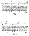
- Figure 2 shows the constitution of a carcass 2 known by the EP 0 429 357, made of helical winding around an axis XX of a strip 7 formed in S flattened, provided with a wave support 8.
- the inner gaps 9 appearing between adjacent turns form a well closed and are the cause of swirls symbolized by lines 10 at the level the flow of gaseous fluid in the pipe, the general flow of which is symbolized by the arrow 11.
- the outer gaps 12 are closed by the plastic layer of the sheath 3 that surrounds the carcass and flows slightly in the gaps 11 by forming indentations 13.
- the thickness of the strip 7, which is generally of the order of 2 mm, is traversed by perforations 20, 21 intended to make communicate the inner gaps 9 with the adjacent spaces inside turns.
- Perforations (or any other form of localized openings) are planned at the level of the inner gaps 9, as seen for the orifices 20, made in the central portion of strip 7 joining the two S loops, and / or for the orifices 21 formed in the loop end of the S located on the side of the inner gap 9.
- Other perforations, such as orifices 22 formed in the loop end of the S on the side of the junction outside 12, can be provided to increase the total volume expansion and communication accessible through the various orifices, 9.
- the gap 9 is thus put in communication through the orifices 21 with the first interior volume 23 of the loop of S and also, via the orifices 20 and 22, with the second volume inside 24 of the loop of S, separated from the first volume by the wave 8.
- the wave 8 may itself have through-holes for improve the flow of gas, although the purpose and to attenuate the eddies is not the flow of gas in the carcass all along, but rather the modification of the local conditions of the flow in the vicinity of the inner gaps 9. Local conditions of the flow in the vicinity of the inner gaps 9 are thus modified through the holes 20 to 22 so that the vortices can not take birth or at least the resonance likely to be generated by the swirls do not happen.
- the succession of holes 20 to 22 is advantageously arranged parallel to the flow 11 and the axis XX of the conduct, on the one hand within each turn (which results from the positioning the alignment of the holes on the strip strip 7 itself) and on the other hand from one turn to the other (which results from a between the pitch of the holes along the strip of strip and the diameter winding thereof); each hole 20 to 22 is itself oriented parallel to the axis XX and substantially in an intermediate cylinder between the inner and outer cylindrical shells of the winding of the turns in S, so as to intersect the inner gaps 9.
- FIG. 5 shows a strip strip portion 7, before forming in S, in which are provided three lines of perforations 22, 20 and 21.
- the thickness e of the strip 7 is 1.8 mm.
- the width L of the strip of strip is 72 mm, the spacing E between the lines of holes is 20 mm, the line of holes 20, central, being at a distance D of 36 mm from the edge.
- the distance d between two consecutive holes in a line is 5 to 10 times the diameter of the perforation 20 to 22, which diameter is of the order of the thickness e of the strip.
- the height H of the turns formed is typically 9 mm and the pitch P of 24 mm.
- these numerical examples, as well as the form, the number and dimensions of the holes are likely to vary depending of each application and are in no way limiting.
Landscapes
- Engineering & Computer Science (AREA)
- General Engineering & Computer Science (AREA)
- Mechanical Engineering (AREA)
- Life Sciences & Earth Sciences (AREA)
- Geology (AREA)
- Mining & Mineral Resources (AREA)
- Physics & Mathematics (AREA)
- Environmental & Geological Engineering (AREA)
- Fluid Mechanics (AREA)
- General Life Sciences & Earth Sciences (AREA)
- Geochemistry & Mineralogy (AREA)
- Rigid Pipes And Flexible Pipes (AREA)
Claims (11)
- Flexible röhrenförmige Leitung für den Transport von insbesondere gasförmigen Kohlenwasserstoffen, wobei die Leitung von der Art ist, umfassend wenigstens eine Karkasse bzw. Körper (2), ein inneres Druckrohr (3) und eine oder mehrere Armierungsummantelungen bzw. -schichten (5), und wobei die Karkasse (2), welche des am weitesten innen liegende Element der Leitung ausbildet, aus einer zusammengeklammerten bzw. -gefalzten windungs- bzw. spiralförmigen Ummantelung bzw. Umwicklung aus einem profilierten bandartigen oder formfadenförmigen Element (7) gebildet ist, dadurch gekennzeichnet, daß die Windungen bzw. Spiralen der Karkasse (2) in der Dicke des profilierten Elements (7) querverlaufende Durchgänge (20, 21, 22) umfassen, die dazu bestimmt sind, den Abfluß des Kohlenwasserstoffs, der in der Leitung zirkuliert, zum Inneren der Windungen der Karkasse (2) zu ermöglichen.
- Leitung nach Anspruch 1, deren Windungen der Karkasse (2) untereinander innere Öffnungen bzw. Durchbrechungen (9) ausbilden, dadurch gekennzeichnet, daß die Durchtritte (20, 21) auf dem Niveau der inneren Durchbrechungen (9) zwischen den Windungen angeordnet sind.
- Leitung nach einem der Ansprüche 1 oder 2, dadurch gekennzeichnet, daß die Durchtritte (20, 21, 22) durch Löcher (20, 21, 22) ausgebildet sind, die in der Dicke des profilierten Elements ausgeführt sind, welches die Windungen der Karkasse (2) ausbildet.
- Leitung nach Anspruch 3, dadurch gekennzeichnet, daß die Löcher (20, 21, 22) im wesentlichen parallel zur Achse (XX) der Leitung ausgerichtet bzw. orientiert sind.
- Leitung nach Anspruch 4, dadurch gekennzeichnet, daß die von ein und derselben Windung aufeinanderfolgenden Löcher (20, 21, 22) parallel zur Achse (XX) der Leitung ausgerichtet sind.
- Leitung nach Anspruch 5, dadurch gekennzeichnet, daß die Löcher (20, 21, 22) von aufeinanderfolgenden Windungen parallel zur Achse (XX) der Leitung ausgerichtet sind.
- Leitung nach einem der vorhergehenden Ansprüche, dadurch gekennzeichnet, daß die Karkasse (2) aus einem S-förmig geformten Band (7) gebildet ist.
- Leitung nach Anspruch 7, dadurch gekennzeichnet, daß die Löcher (20, 21, 22) in wenigstens einer von drei aufeinanderfolgenden Zonen des S vorgesehen sind: einer zentralen Zone, Endzonen der Schleifen des S.
- Leitung nach einem der Ansprüche 7 oder 8, dadurch gekennzeichnet, daß die Löcher (20, 21, 22) einen Durchmesser in der Größe der Dicke des Bands (7) aufweisen.
- Leitung nach einem der Ansprüche 7 bis 9, dadurch gekennzeichnet, daß die Löcher (20, 21, 22) entlang des Bands (7) um einen Abstand in der Größenordnung von 5 bis 10 mal ihrem Durchmesser beabstandet sind.
- Herstellungsverfahren für eine flexible rohrförmige Leitung für den Transport von insbesondere gasförmigen Kohlenwasserstoffen, wobei die Leitung von der Art ist, umfassend wenigstens eine Karkasse (2), ein inneres Druckrohr (3) und eine oder mehrere Armierungsummantelung(en) (5), und wobei die Karkasse (2) das am weitesten innen liegende Element der Leitung ausbildet, wobei das Verfahren der Art ist, welche die Profilierung und Umwicklung in Windungen eines Bands (7) in der Art umfaßt, um die Klammer- bzw. Falzverbindung der Windungen untereinander zu realisieren, dadurch gekennzeichnet, daß das Band (7) vorab derart perforiert ist, um, sobald die Windungen zum Realisieren der Karkasse (2) ausgebildet werden, die querverlaufenden Durchtritte (20, 21, 22) auszubilden, die für ein Ergießen in Richtung zum Inneren der Windungen der Karkasse des in der Leitung zirkulierenden Kohlenwasserstoffs bestimmt sind.
Applications Claiming Priority (3)
| Application Number | Priority Date | Filing Date | Title |
|---|---|---|---|
| FR0845402 | 2002-07-05 | ||
| FR0208454 | 2002-07-05 | ||
| PCT/FR2003/002020 WO2004005785A1 (fr) | 2002-07-05 | 2003-06-30 | Conduite tubulaire flexible pour le transport d'hydrocarbures a carcasse anti-turbulence |
Publications (2)
| Publication Number | Publication Date |
|---|---|
| EP1546596A1 EP1546596A1 (de) | 2005-06-29 |
| EP1546596B1 true EP1546596B1 (de) | 2005-11-16 |
Family
ID=30011394
Family Applications (1)
| Application Number | Title | Priority Date | Filing Date |
|---|---|---|---|
| EP03762715A Expired - Lifetime EP1546596B1 (de) | 2002-07-05 | 2003-06-30 | Flexible röhrenförmige leitung zur beförderung von kohlenwasserstoffen mit strömungsbildung verhindernder karkasse |
Country Status (5)
| Country | Link |
|---|---|
| EP (1) | EP1546596B1 (de) |
| AU (1) | AU2003264677A1 (de) |
| DK (1) | DK1546596T3 (de) |
| NO (1) | NO336994B1 (de) |
| WO (1) | WO2004005785A1 (de) |
Families Citing this family (10)
| Publication number | Priority date | Publication date | Assignee | Title |
|---|---|---|---|---|
| DK1636246T3 (en) * | 2003-06-24 | 2015-11-23 | Scientist Of Fortune Sa | Preparation of 2-desoxynucleosider and 2-desoxynucleosidforstadier from 2-dehydro-3-deoxy-D-gluconate |
| FR2905444B1 (fr) | 2006-08-30 | 2009-12-25 | Technip France | Carcasse de conduite tubulaire en feuillard agrafe et conduite comportant une telle carcasse |
| FR2915552B1 (fr) | 2007-04-27 | 2009-11-06 | Technip France | Conduite tubulaire flexible pour le transport d'hydrocarbures gazeux. |
| FR2930622B1 (fr) * | 2008-04-25 | 2014-02-28 | Inst Francais Du Petrole | Conduite flexible munie d'une carcasse pour limiter les vibrations acoustiques |
| BR112013024458A2 (pt) * | 2011-03-25 | 2016-12-20 | Nat Oilwell Varco Lp | método para reduzir o risco de falha de um sistema de riser de perfuração, riser de perfuração e método para instalação de um membro interno em espiral dentro de um riser de perfuração |
| GB201306665D0 (en) | 2013-04-12 | 2013-05-29 | Wellstream Int Ltd | Elongate tape element and method |
| FR3017438B1 (fr) | 2014-02-11 | 2016-10-14 | Technip France | Conduite flexible de transport de fluide et procede associe |
| WO2015169322A1 (en) * | 2014-05-08 | 2015-11-12 | National Oilwell Varco Denmark I/S | A flexible metal tube |
| US10203053B2 (en) | 2014-10-03 | 2019-02-12 | Hose Master Llc | Fluid permeable hose carcass |
| FR3120109B1 (fr) * | 2021-02-25 | 2023-02-24 | Technip N Power SAS | Conduite flexible avec au moins un orifice de circulation de gaz oblique, et procédé de fabrication associé |
Family Cites Families (2)
| Publication number | Priority date | Publication date | Assignee | Title |
|---|---|---|---|---|
| DE899885C (de) * | 1940-07-27 | 1953-12-17 | Pforzheim Metallschlauch | Metallschlauch und Verfahren zu seiner Herstellung |
| FR2654795B1 (fr) | 1989-11-21 | 1992-03-06 | Coflexip | Conduite tubulaire flexible. |
-
2003
- 2003-06-30 DK DK03762715T patent/DK1546596T3/da active
- 2003-06-30 WO PCT/FR2003/002020 patent/WO2004005785A1/fr not_active Ceased
- 2003-06-30 AU AU2003264677A patent/AU2003264677A1/en not_active Abandoned
- 2003-06-30 EP EP03762715A patent/EP1546596B1/de not_active Expired - Lifetime
-
2004
- 2004-12-22 NO NO20045608A patent/NO336994B1/no not_active IP Right Cessation
Also Published As
| Publication number | Publication date |
|---|---|
| NO20045608L (no) | 2005-03-03 |
| WO2004005785A1 (fr) | 2004-01-15 |
| EP1546596A1 (de) | 2005-06-29 |
| NO336994B1 (no) | 2015-12-14 |
| AU2003264677A1 (en) | 2004-01-23 |
| DK1546596T3 (da) | 2006-03-20 |
Similar Documents
| Publication | Publication Date | Title |
|---|---|---|
| CA2528354C (fr) | Conduite tubulaire flexible pour le transport de fluide et notamment d'hydrocarbures gazeux, a carcasse et gaine interne anti-turbulence | |
| CA2661126C (fr) | Conduite flexible de transport d'hydrocarbures comportant une carcasse de conduite tubulaire en feuillard agrafe | |
| EP0937932B1 (de) | Flexible Rohrleitung für Steigrohrleitung für Ölgewinnung aus dem Meer | |
| EP1440269B1 (de) | Flexible röhrenförmige leitung für den transport von kohlenwasserstoffen mit einem gerippe bestehend aus einem mit einem eisenband gehefteten länglichen element | |
| CA2519181C (fr) | Conduite tubulaire flexible pour le transport d`un fluide | |
| EP1104527B1 (de) | Biegsame rohrleitung mit kriechbegrenzter dichtschicht | |
| EP1395769B1 (de) | Flexible rohrleitung mit von unten geklammertem druckgewölbe | |
| EP1546596B1 (de) | Flexible röhrenförmige leitung zur beförderung von kohlenwasserstoffen mit strömungsbildung verhindernder karkasse | |
| FR2782142A1 (fr) | Conduite flexible a enroulement de fil de forme en i | |
| EP1419338B1 (de) | Eine lage eines für kohlenwasserstofftransport verwendeten flexiblen kanals bildender flacher textilstreifen und so hergestellter kanal | |
| FR2727738A1 (fr) | Conduite tubulaire flexible comportant une nappe d'armure agrafee | |
| FR2915552A1 (fr) | Conduite tubulaire flexible pour le transport d'hydrocarbures gazeux. | |
| FR2802608A1 (fr) | Conduite flexible sous-marine de grande longueur a structure evolutive | |
| EP1423634B1 (de) | Flexibles rohr zum transport eines fluids | |
| EP1561061B1 (de) | Flexible röhrenförmige leitung zum fluidtransport | |
| FR2930622A1 (fr) | Conduite flexible munie d'une carcasse pour limiter les vibrations acoustiques | |
| EP1154184B2 (de) | Biegsame Leitung mit Wickeldraht oder Wickelband zur Unterstützung der Verstärkungseinlagen | |
| FR2904992A1 (fr) | Conduite flexible stabilisee resistante en compression axiale. | |
| FR3119432A1 (fr) | Conduite flexible de transport de fluide et procédé de fabrication associé |
Legal Events
| Date | Code | Title | Description |
|---|---|---|---|
| PUAI | Public reference made under article 153(3) epc to a published international application that has entered the european phase |
Free format text: ORIGINAL CODE: 0009012 |
|
| GRAP | Despatch of communication of intention to grant a patent |
Free format text: ORIGINAL CODE: EPIDOSNIGR1 |
|
| 17P | Request for examination filed |
Effective date: 20050207 |
|
| AK | Designated contracting states |
Kind code of ref document: A1 Designated state(s): AT BE BG CH CY CZ DE DK EE ES FI FR GB GR HU IE IT LI LU MC NL PT RO SE SI SK TR |
|
| AX | Request for extension of the european patent |
Extension state: AL LT LV MK |
|
| RBV | Designated contracting states (corrected) |
Designated state(s): DK FR GB IE NL |
|
| REG | Reference to a national code |
Ref country code: DE Ref legal event code: 8566 |
|
| GRAS | Grant fee paid |
Free format text: ORIGINAL CODE: EPIDOSNIGR3 |
|
| GRAA | (expected) grant |
Free format text: ORIGINAL CODE: 0009210 |
|
| AK | Designated contracting states |
Kind code of ref document: B1 Designated state(s): DK FR GB IE NL |
|
| REG | Reference to a national code |
Ref country code: GB Ref legal event code: FG4D Free format text: NOT ENGLISH |
|
| REG | Reference to a national code |
Ref country code: IE Ref legal event code: FG4D Free format text: LANGUAGE OF EP DOCUMENT: FRENCH |
|
| GBT | Gb: translation of ep patent filed (gb section 77(6)(a)/1977) |
Effective date: 20060208 |
|
| REG | Reference to a national code |
Ref country code: DK Ref legal event code: T3 |
|
| PLBE | No opposition filed within time limit |
Free format text: ORIGINAL CODE: 0009261 |
|
| STAA | Information on the status of an ep patent application or granted ep patent |
Free format text: STATUS: NO OPPOSITION FILED WITHIN TIME LIMIT |
|
| 26N | No opposition filed |
Effective date: 20060817 |
|
| PGFP | Annual fee paid to national office [announced via postgrant information from national office to epo] |
Ref country code: IE Payment date: 20130527 Year of fee payment: 11 |
|
| PGFP | Annual fee paid to national office [announced via postgrant information from national office to epo] |
Ref country code: NL Payment date: 20130516 Year of fee payment: 11 Ref country code: FR Payment date: 20130607 Year of fee payment: 11 |
|
| REG | Reference to a national code |
Ref country code: NL Ref legal event code: V1 Effective date: 20150101 |
|
| REG | Reference to a national code |
Ref country code: IE Ref legal event code: MM4A |
|
| REG | Reference to a national code |
Ref country code: FR Ref legal event code: ST Effective date: 20150227 |
|
| PG25 | Lapsed in a contracting state [announced via postgrant information from national office to epo] |
Ref country code: NL Free format text: LAPSE BECAUSE OF NON-PAYMENT OF DUE FEES Effective date: 20150101 |
|
| PG25 | Lapsed in a contracting state [announced via postgrant information from national office to epo] |
Ref country code: IE Free format text: LAPSE BECAUSE OF NON-PAYMENT OF DUE FEES Effective date: 20140630 |
|
| PG25 | Lapsed in a contracting state [announced via postgrant information from national office to epo] |
Ref country code: FR Free format text: LAPSE BECAUSE OF NON-PAYMENT OF DUE FEES Effective date: 20140630 |
|
| PGFP | Annual fee paid to national office [announced via postgrant information from national office to epo] |
Ref country code: GB Payment date: 20150619 Year of fee payment: 13 Ref country code: DK Payment date: 20150520 Year of fee payment: 13 |
|
| REG | Reference to a national code |
Ref country code: DK Ref legal event code: EBP Effective date: 20160630 |
|
| GBPC | Gb: european patent ceased through non-payment of renewal fee |
Effective date: 20160630 |
|
| PG25 | Lapsed in a contracting state [announced via postgrant information from national office to epo] |
Ref country code: GB Free format text: LAPSE BECAUSE OF NON-PAYMENT OF DUE FEES Effective date: 20160630 |
|
| PG25 | Lapsed in a contracting state [announced via postgrant information from national office to epo] |
Ref country code: DK Free format text: LAPSE BECAUSE OF NON-PAYMENT OF DUE FEES Effective date: 20160630 |