EP1547634A1 - Sicherheitsspritze - Google Patents
Sicherheitsspritze Download PDFInfo
- Publication number
- EP1547634A1 EP1547634A1 EP04105886A EP04105886A EP1547634A1 EP 1547634 A1 EP1547634 A1 EP 1547634A1 EP 04105886 A EP04105886 A EP 04105886A EP 04105886 A EP04105886 A EP 04105886A EP 1547634 A1 EP1547634 A1 EP 1547634A1
- Authority
- EP
- European Patent Office
- Prior art keywords
- holder
- needle
- flexible
- plunger
- sealing member
- Prior art date
- Legal status (The legal status is an assumption and is not a legal conclusion. Google has not performed a legal analysis and makes no representation as to the accuracy of the status listed.)
- Granted
Links
- 238000007789 sealing Methods 0.000 claims abstract description 126
- 125000006850 spacer group Chemical group 0.000 claims description 28
- 239000011796 hollow space material Substances 0.000 claims description 2
- 230000000149 penetrating effect Effects 0.000 claims 1
- 239000003814 drug Substances 0.000 description 13
- 238000012986 modification Methods 0.000 description 3
- 230000004048 modification Effects 0.000 description 3
- 238000000034 method Methods 0.000 description 2
- 208000030507 AIDS Diseases 0.000 description 1
- 208000035473 Communicable disease Diseases 0.000 description 1
- 239000008280 blood Substances 0.000 description 1
- 210000004369 blood Anatomy 0.000 description 1
- 238000010586 diagram Methods 0.000 description 1
- 201000010099 disease Diseases 0.000 description 1
- 208000037265 diseases, disorders, signs and symptoms Diseases 0.000 description 1
- 208000002672 hepatitis B Diseases 0.000 description 1
- 238000002347 injection Methods 0.000 description 1
- 239000007924 injection Substances 0.000 description 1
- 238000004519 manufacturing process Methods 0.000 description 1
- 238000010415 tidying Methods 0.000 description 1
Images


Classifications
-
- A—HUMAN NECESSITIES
- A61—MEDICAL OR VETERINARY SCIENCE; HYGIENE
- A61M—DEVICES FOR INTRODUCING MEDIA INTO, OR ONTO, THE BODY; DEVICES FOR TRANSDUCING BODY MEDIA OR FOR TAKING MEDIA FROM THE BODY; DEVICES FOR PRODUCING OR ENDING SLEEP OR STUPOR
- A61M5/00—Devices for bringing media into the body in a subcutaneous, intra-vascular or intramuscular way; Accessories therefor, e.g. filling or cleaning devices, arm-rests
- A61M5/178—Syringes
- A61M5/31—Details
- A61M5/32—Needles; Details of needles pertaining to their connection with syringe or hub; Accessories for bringing the needle into, or holding the needle on, the body; Devices for protection of needles
- A61M5/3205—Apparatus for removing or disposing of used needles or syringes, e.g. containers; Means for protection against accidental injuries from used needles
- A61M5/321—Means for protection against accidental injuries by used needles
- A61M5/322—Retractable needles, i.e. disconnected from and withdrawn into the syringe barrel by the piston
- A61M5/3234—Fully automatic needle retraction, i.e. in which triggering of the needle does not require a deliberate action by the user
-
- A—HUMAN NECESSITIES
- A61—MEDICAL OR VETERINARY SCIENCE; HYGIENE
- A61M—DEVICES FOR INTRODUCING MEDIA INTO, OR ONTO, THE BODY; DEVICES FOR TRANSDUCING BODY MEDIA OR FOR TAKING MEDIA FROM THE BODY; DEVICES FOR PRODUCING OR ENDING SLEEP OR STUPOR
- A61M5/00—Devices for bringing media into the body in a subcutaneous, intra-vascular or intramuscular way; Accessories therefor, e.g. filling or cleaning devices, arm-rests
- A61M5/178—Syringes
- A61M5/31—Details
- A61M5/32—Needles; Details of needles pertaining to their connection with syringe or hub; Accessories for bringing the needle into, or holding the needle on, the body; Devices for protection of needles
- A61M5/3205—Apparatus for removing or disposing of used needles or syringes, e.g. containers; Means for protection against accidental injuries from used needles
- A61M5/321—Means for protection against accidental injuries by used needles
- A61M5/322—Retractable needles, i.e. disconnected from and withdrawn into the syringe barrel by the piston
- A61M5/3221—Constructional features thereof, e.g. to improve manipulation or functioning
- A61M2005/3231—Proximal end of needle captured or embedded inside piston head, e.g. by friction or hooks
-
- A—HUMAN NECESSITIES
- A61—MEDICAL OR VETERINARY SCIENCE; HYGIENE
- A61M—DEVICES FOR INTRODUCING MEDIA INTO, OR ONTO, THE BODY; DEVICES FOR TRANSDUCING BODY MEDIA OR FOR TAKING MEDIA FROM THE BODY; DEVICES FOR PRODUCING OR ENDING SLEEP OR STUPOR
- A61M5/00—Devices for bringing media into the body in a subcutaneous, intra-vascular or intramuscular way; Accessories therefor, e.g. filling or cleaning devices, arm-rests
- A61M5/178—Syringes
- A61M5/31—Details
- A61M5/32—Needles; Details of needles pertaining to their connection with syringe or hub; Accessories for bringing the needle into, or holding the needle on, the body; Devices for protection of needles
- A61M5/3205—Apparatus for removing or disposing of used needles or syringes, e.g. containers; Means for protection against accidental injuries from used needles
- A61M5/321—Means for protection against accidental injuries by used needles
- A61M5/322—Retractable needles, i.e. disconnected from and withdrawn into the syringe barrel by the piston
- A61M5/3234—Fully automatic needle retraction, i.e. in which triggering of the needle does not require a deliberate action by the user
- A61M2005/3239—Fully automatic needle retraction, i.e. in which triggering of the needle does not require a deliberate action by the user triggered by dislodgement of outer part anchoring the needle portion to the inside of the syringe barrel wall, e.g. a ring-shaped portion
-
- A—HUMAN NECESSITIES
- A61—MEDICAL OR VETERINARY SCIENCE; HYGIENE
- A61M—DEVICES FOR INTRODUCING MEDIA INTO, OR ONTO, THE BODY; DEVICES FOR TRANSDUCING BODY MEDIA OR FOR TAKING MEDIA FROM THE BODY; DEVICES FOR PRODUCING OR ENDING SLEEP OR STUPOR
- A61M5/00—Devices for bringing media into the body in a subcutaneous, intra-vascular or intramuscular way; Accessories therefor, e.g. filling or cleaning devices, arm-rests
- A61M5/178—Syringes
- A61M5/31—Details
- A61M5/32—Needles; Details of needles pertaining to their connection with syringe or hub; Accessories for bringing the needle into, or holding the needle on, the body; Devices for protection of needles
- A61M5/3205—Apparatus for removing or disposing of used needles or syringes, e.g. containers; Means for protection against accidental injuries from used needles
- A61M5/321—Means for protection against accidental injuries by used needles
- A61M5/322—Retractable needles, i.e. disconnected from and withdrawn into the syringe barrel by the piston
- A61M5/3234—Fully automatic needle retraction, i.e. in which triggering of the needle does not require a deliberate action by the user
- A61M2005/3241—Needle retraction energy is accumulated inside of a hollow plunger rod
- A61M2005/3242—Needle retraction by vacuum
-
- A—HUMAN NECESSITIES
- A61—MEDICAL OR VETERINARY SCIENCE; HYGIENE
- A61M—DEVICES FOR INTRODUCING MEDIA INTO, OR ONTO, THE BODY; DEVICES FOR TRANSDUCING BODY MEDIA OR FOR TAKING MEDIA FROM THE BODY; DEVICES FOR PRODUCING OR ENDING SLEEP OR STUPOR
- A61M5/00—Devices for bringing media into the body in a subcutaneous, intra-vascular or intramuscular way; Accessories therefor, e.g. filling or cleaning devices, arm-rests
- A61M5/50—Devices for bringing media into the body in a subcutaneous, intra-vascular or intramuscular way; Accessories therefor, e.g. filling or cleaning devices, arm-rests having means for preventing re-use, or for indicating if defective, used, tampered with or unsterile
- A61M5/508—Means for preventing re-use by disrupting the piston seal, e.g. by puncturing
Definitions
- the present invention relates to a medical syringe, and more particularly to a safety syringe with an automatically retractable needle.
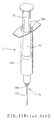
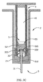
- a prior syringe includes a syringe barrel 72 with a hole in the front end of the syringe barrel 72 and scales on the surface of the syringe barrel 72.
- a needle unit 73 includes needle holder 730 with the thread of a screw for bolting the needle unit 73 in the syringe barrel 72.
- the rear end of the needle 731 is fastened across the needle holder 730, wherein the front end of the needle 731 is projected from the needle holder 730.
- the rear end of the syringe barrel 72 includes a rear opening 724 with large cross-sectional area or the diameter.
- a rubber-sealing ring 743 fastens a rod 74 inside the syringe barrel 72, wherein the rod 74 is movable across the rear opening 724.
- the external diameter of the rubber-sealing ring 743 is slightly larger than the internal diameter of the rear opening 724 and the internal diameter of the syringe barrel 72.
- the rubber-sealing ring 743 injects the medicament withdrawn inside the syringe barrel 72 through the needle 731 when the rod 74 is pushed.
- the needle 731 may accidentally stab an operating staff while the operating staff encloses the needle 731 by a needle sheath. If the syringe 7 is used and the needle 731 comes in contact with the blood of an individual, the stabbed operating staff may become infected with diseases, e.g. AIDS, viral hepatitis b and so on.
- diseases e.g. AIDS, viral hepatitis b and so on.
- a safety syringe 8 which is disclosed by U.S. Patent NO. 5, 395, 337, includes a syringe barrel 82 and a spring 84.
- the syringe barrel 82 includes a tapered wall 824 for fastening a needle holder 830.
- a flexible sealing member 85 is wedged in the front end of the spring 84 by a retaining ring 850 having a lead angle.
- a spring 86 connects with the flexible sealing member 85 to pull the flexible sealing member 85 when the operating staff finishes the injection.
- the operating staff can tidy the needle 831 by pushing the spring 84 to wedge the flexible sealing member 85 by the tapered wall 824.
- the tapered wall 824 wedges the flexible-sealing member 85
- the flexible sealing member 85 is released from the retaining ring 850 if the operating staff continuously pushes the spring 84.
- the flexible sealing member 85 is pulled by the spring 86 to movably dispose inside the spring 84 after the flexible-sealing member 85 is released from the retaining ring 850.
- the diameter of the tapered wall 824 of a syringe is very small, e.g. few millimeters, wherein the capacity of the syringe is approximately 1 cubic centimeter or 2 cubic centimeters. It is pretty difficult to push the tapered wall 824 while wedging the flexible-sealing member 85 by the tapered wall 824 without partiality. It is also difficult to set the spring 86 in the spring 84 to connect the flexible sealing member 85 with the rear end of the spring 84 of a tiny syringe 7. The complex and delicate process for fabricating elements of the tiny syringe 7 increases the cost of the tiny syringe 7. The syringe 7 may be too expensive for selling. Thus it is necessary to develop more economical safety syringes for protecting the operating staff from being stabbed.
- a safety syringe is provided to substantially overcome the drawbacks of the above mentioned problems for automatically retracting the needle unit inside a plunger by pressure.
- a safety syringe in accordance with the present invention, includes a syringe barrel, a flexible holder-supporting seat, a needle unit, a plunger and a flexible sealing member.
- the syringe barrel includes a barrel body with a front opening and a rear opening, wherein the cross-sectional area or the diameter of the rear opening is larger than the front opening.
- a spacer portion is disposed in the front end of the barrel body, wherein the front opening penetrates the spacer portion.
- the flexible holder-supporting seat is sleeved around and clamps a needle holder of the needle unit within the front-end portion of a syringe barrel, wherein the flexible holder-supporting seat includes a through hole.
- the needle unit includes the needle holder and a needle fastened on the needle holder, wherein the needle includes a rear opening.
- the needle unit is inserted into the front end of the syringe barrel.
- the needle holder is propped by a spacer portion. The needle inserts through the spacer portion and is projected from the front opening.
- the plunger includes a front-end wall, a rear end wall and a plunger body formed between the front-end wall and the rear end wall.
- the cross-sectional area or the diameter of a front opening of the plunger is larger than the external diameter of the spacer portion.
- An inward flange is formed in the front portion of the plunger.
- the plunger is disposed inside the syringe barrel and is movable between the flexible holder-supporting seat and the rear opening.
- the sealing member is disposed continuously within the inward flange to seal the front opening formed in the front of the plunger for defining a sealed space with lower pressure.
- the sealing member combines with the needle unit when the front end of the plunger is pushed to be close to the holder-supporting seat.
- the plunger pushes the holder-supporting seat to release the needle holder combined with the sealing member.
- the needle holder is propped by the spacer portion to stop the movement of the sealing member, so the sealing member is released from the inward flange while the sealing member being not contacted by the inward flange.
- the sealing member and the needle unit is automatically retracted into the plunger body due to negative pressure.
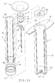
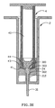
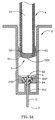
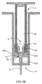
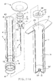
- the first embodiment of the present invention provides a safety syringe including a syringe barrel 2, a needle unit 3 set in the front end of the syringe barrel 2, a plunger 4 movably disposed within the syringe barrel 2 and a flexible sealing member 5 disposed movably within the front end of the plunger 4.
- the syringe barrel 2 includes a barrel body 20, a front-end wall 21 and a rear end wall 22.
- a front opening 210 and the front-end wall 21 are integrally formed.
- a rear opening 220 is formed integrally with the rear end wall 22.
- the cross-sectional area of the rear opening 220 is slightly larger than the cross-sectional area of the plunger 4; thus the plunger 4 can be inserted into the syringe barrel 2.
- a spacer portion 212 is disposed on the front end wall 21, wherein the front opening 210 penetrates the spacer portion 212.
- the spacer portion 212 and the barrel body 20 can be formed integrally. However, the spacer portion 212 may be an independent element set on the front end of the barrel body 20.
- the cross-sectional area or the diameter of the front opening 210 is slightly smaller than that of the rear opening 220 and the plunger 4.
- the internal diameter of the syringe barrel 2 and the internal diameter of the rear opening 220 are approximately the same.
- a flexible holder-supporting seat 24 including a central hole 240 can be pushed into the syringe barrel 2 through the rear opening 220 to be set inside the syringe barrel 2. There is a distance between the flexible holder-supporting seat 24 and the front-end wall 21 of the barrel body 20.
- a needle unit 3 includes a needle body 30 and a needle 31 set across the needle body 30.
- the needle body 30 is movably set inside the flexible holder-supporting seat 24.
- the front end of the needle 31 is set across the spacer portion 212 to pierce through the spacer portion 212.
- the plunger 4 includes a plunger body 40 including an open front end 41 formed on an end of plunger body 40.
- the open front end 41 includes a front opening 410, wherein the internal diameter of the front opening 410 is slightly larger than the cross-sectional area or the diameter of the needle body 30.
- a flexible sealing member 5 is fastened inside the front opening 410 to form a sealed space inside the plunger body 40.
- a rear end wall 45 is fastened on another end of plunger body 40 to form the sealed space inside the plunger body 40.
- the plunger 4 fastened inside the barrel body 20 can be moved away from the syringe barrel 2 by pulling the rear end wall 45 to withdraw the medicament.
- the plunger 4 can be pushed to inject the medicament by pushing the rear end wall 45.
- the plunger body 40 may include a rubber seal ring 43 to fasten the syringe barrel 2 and the plunger 4 better for preventing the medicament inside syringe barrel 2 from overflowing.
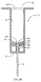
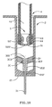
- the flexible holder-supporting seat 24 is set inside the syringe barrel 2 to fasten the needle body 30 on.
- the needle body 30 includes a needle holder 302, a rear opening 300 and an outward flange 303, wherein the cross-sectional area or the diameter of the outward flange 303 is slightly larger than that of the needle holder 302.
- the cross-sectional area or the diameter of the needle holder 302 may be equal to or slightly larger than that of the spacer portion 212.
- the flexible holder-supporting seat 24 includes a rear end surface 241. The side of the central hole 240 of the flexible holder-supporting seat 24 fastens the needle holder 302 when the needle body 30 is stuffed into the flexible holder-supporting seat 24.
- the side of the central hole 240 also fastens the outward flange 303.
- the needle body 30 and the flexible holder-supporting seat 24 can be pushed into the syringe barrel 2 through the rear opening 220 until the needle holder 302 contacting with the spacer portion 212.
- the needle unit 3 set on the front end of the syringe barrel 2 is fastened well and stable because the area of the needle holder 302 contacting with the spacer portion 212 is large enough to provide enough force of stability.
- the layout of the prevent invention provides effective stability of the safety syringe for fastening the needle unit 3 and the syringe barrel 2.
- an inward flange 44 of the plunger 4 fastens the flexible sealing member 5.
- a rear opening 420 and the open rear end 42 are formed integrally.
- the plunger 4 further comprises a rear end wall 45 sealing the rear opening 420.
- the rear end wall 45 includes a plate 452 and a circular projection 451 extended from the plate 452.
- the circular projection 451 is fastened inside the plunger body 40 of the plunger 4, wherein the external diameter of the circular projection 451 is a slightly larger than the internal diameter of the rear opening 420 of the plunger 4.
- the flexible sealing member 5 includes a sealing rear portion 52 and a holder-retaining front portion 51 extended from the front end of the sealing rear portion 52.
- the flexible sealing member 5 further includes a rear end skirt portion 53 in the rear end of the flexible sealing member 5.
- the external diameter of the sealing rear portion 52 is slightly smaller than the internal diameter of the rear opening 420, the sealing rear portion 52 can be pushed into the rear opening 420 of the plunger body 40 thus.
- the external diameter of the sealing rear portion 52 is slightly larger than the internal diameter of the inward flange 44 of the plunger 4.
- the flexible sealing member 5 can be fastened on the open front end 41 by fastening to the inward flange 44 to seal the space inside the plunger 4.
- a rubber seal ring 43 is covered on the front end of the plunger 4, wherein the external diameter of the rubber seal ring 43 is slightly larger than the internal diameter of the barrel body 20.
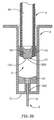
- the cannular holder-retaining front portion 51 of the flexible sealing member 5 is extended forward from the sealing rear portion 52, and the external diameter of the holder-retaining front portion 51 is as small as the forward extension.
- a blind hole 510 is formed inside the holder-retaining front portion 51, wherein the bottom of the blind hole 510 is a sealing rear portion 520, and the top of the blind hole 510 is surrounded by the front end of the holder-retaining front portion 51.
- the internal diameter of the front end of the holder-retaining front portion 51 is slightly smaller than the external diameter of the outward flange 303.
- the plunger 4 is set inside the syringe barrel 2.
- the blind hole 510 sleeves around the outward flange 303.
- the sealing rear portion 520 seals the rear opening 300 of the needle body 30 to stop the medicament from being injected, when the open front end 41 is pushed to contact with the flexible holder-supporting seat 24.
- the needle holder 302 is fastened on the spacer portion 212 but the open front end 41 continuously pushes the flexible holder-supporting seat 24.
- the flexible holder-supporting seat 24 does not fasten the needle body 30, if the flexible holder-supporting seat 24 is pushed continuously by the open front end 41.
- the flexible sealing member 5 stops moving because the needle body 30 props the flexible sealing member 5 up, even if the open front end 41 continuously pushes the flexible holder-supporting seat 24.
- the flexible sealing member 5 is released from the inward flange 44 when the inward flange 44 does not contact with the flexible sealing member 5.
- the pressure inside the space sealed by the sealing rear portion 52 and the plunger body 40 is lower than the pressure pulling the sealing rear portion 52.
- the needle unit 3 that is combined with the flexible sealing member 5 is automatically retracted into the plunger body 40 due to the different pressures.
- the operating staffs using the safety syringe of the present invention are protected from being stabbed.
- the sealing rear portion 52 stops air being transported into the sealed space to maintain the lower pressure of the sealed space inside the plunger body 40.
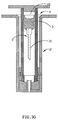
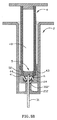
- the safety syringe of the second embodiment of the present invention is illustrated as FIG. 4A-4E.
- the difference between the first embodiment and the second embodiment of the present invention is the length of the holder-retaining front portion 51 of the flexible-sealing member 5.
- the holder-retaining front portion 51 can shrink to sleeve the needle unit 3 when the plunger 4 is pushed to contact with the flexible holder-supporting seat 24.
- the flexible sealing member 5 includes a sealing rear portion 52 and a holder-retaining front portion 51, wherein the external diameter of the sealing rear portion 52 is slightly larger than the internal diameter of the inward flange 44.
- the inward flange 44 can clench the sealing rear portion 52.
- the side in the front end of the inward flange 44 expands slightly and does not contact with the holder-retaining front portion 51.
- the holder-retaining front portion 51 curves because the holder-retaining front portion 51 contacts with the flexible holder-supporting seat 24 and the needle body 30 when the plunger 4 is pushed forward to contact with the flexible holder-supporting seat 24.
- the curved holder-retaining front portion 51 curves continuously to be extruded in the space surrounded by the expanded inward flange 44 and the flexible holder-supporting seat 24 when the plunger 4 is continuously pushed.
- the sealing rear portion 520 of the holder-retaining front portion 51 contacts with the rear opening 300 to stuff the rear opening 300, and the holder-retaining front portion 51 expands due to the outward flange 303.
- the holder-retaining front portion 51 sleeves the outward flange 303 to combine with the needle unit 3 after the plunger 4 is continuously pushed to push the flexible holder-supporting seat 24, wherein the needle body 30 is fastened by the spacer portion 212.
- the needle unit 3 is released from the flexible holder-supporting seat 24 when the flexible holder-supporting seat 24 does not contact with the needle unit 3.
- the flexible sealing member 5 stops moving due to the immovable needle body 30 and then is released from the inward flange 44 because the plunger 4 is continuously pushed to push the flexible holder-supporting seat 24 and release the flexible sealing member 5.
- the needle unit 3 combined with the flexible sealing member 5 is automatically retracted into the plunger body 40 due to the difference between two different pressures.
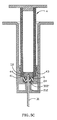
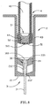
- FIG. 5A-5D illustrates the third embodiment of the present invention.
- the side of the central hole 240 of the flexible holder-supporting seat 24 fastens a U-shaped flexible element 6 including a hole 60.
- the U-shaped flexible element 6 is clenched by the flexible holder-supporting seat 24 and the needle holder 302' .
- the needle 31 projected from the U-shaped flexible element 6 is clenched by the hole 60.
- the external diameter of the U-shaped flexible element 6 is slightly larger than the internal diameter of the plunger 4.
- the needle 31 is fastened by the needle holder 302' and projected from the needle holder 302' .
- the shape of the flexible sealing member 5 of this embodiment is also different from the shape of the flexible sealing member 5 of the above embodiments of the present invention.
- the curved projection 520' of the sealing rear portion 52 may be a cambered surface as shown in FIG. 5A.
- the needle 31 stabs into the curved projection 520' to seal the needle 31 and combine with the U-shaped flexible element 6 and the flexible sealing member 5 when the plunger 4 is pushed to contact with the flexible holder-supporting seat 24.
- FIG. 5B the needle 31 stabs into the curved projection 520' to seal the needle 31 and combine with the U-shaped flexible element 6 and the flexible sealing member 5 when the plunger 4 is pushed to contact with the flexible holder-supporting seat 24.
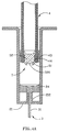
- the fourth embodiment of the present invention provides a safety syringe including a syringe barrel 2 with a different front-end wall 21.
- the front-end wall 21 includes a front opening 210' for fastening a needle 31, wherein the needle 31 projects from the front end wall 21.
- the needle 31 stabs into the sealing rear portion 520 to seal the needle 31 and combine the needle unit 3 with the U-shaped flexible element 6 and the flexible sealing member 5 when the plunger 4 is pushed to contact with the flexible holder-supporting seat 24.
- the flexible holder-supporting seat 24 is pushed by the plunger 4 to slip and release the U-shaped flexible element 6.
- the U-shaped flexible element 6 is also pushed by the plunger 4 until the bottom of the U-shaped flexible element 6 contacting with the needle holder 302.
- the needle 31 stabs into the flexible-sealing member 5 deeper when the U-shaped flexible element 6 is pushed to contact with the needle holder 302.
- the flexible sealing member 5 is pushed by the U-shaped flexible element 6 during the plunger 4 pushes the flexible holder-supporting seat 24.
- the flexible sealing member 5 combining with the needle unit 3 and U-shaped flexible element 6 is withdrawn by the lower pressure inside the plunger 4.
- the needle unit 3, the U-shaped flexible element 6 and the flexible-sealing member 5 is withdrawn into the plunger body 40 due to the pressure.
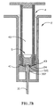
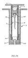
- the fifth embodiment of the present invention is illustrated as FIG. 7A-7D.
- the difference between the first embodiment and the fifth embodiment of the present invention is the structure of the flexible sealing member 5.
- the flexible sealing member 5 includes a holder-retaining front portion 51, a blind hole 510' and a piston body 521, wherein the blind hole 510' is formed within the holder-retaining front portion 51.
- the holder-retaining front portion 51 becomes slightly flat, because the holder-retaining front portion 51 contacts with the needle body 30 when the plunger 4 is pushed forward to be close to the flexible holder-supporting seat 24.
- FIG. 7A-7D The difference between the first embodiment and the fifth embodiment of the present invention is the structure of the flexible sealing member 5.
- the flexible sealing member 5 includes a holder-retaining front portion 51, a blind hole 510' and a piston body 521, wherein the blind hole 510' is formed within the holder-retaining front portion 51.
- the holder-retaining front portion 51 becomes slightly flat, because the holder-retaining front portion 51
- the slightly flat holder-retaining front portion 51 is continuously pushed to combine with the outward flange 303 when the plunger 4 is continuously pushed.
- the piston body 521 contacts with the rear opening 300 to stuff the rear opening 300 to lock the needle 31 from injecting the medicament.
- the holder-retaining front portion 51 sleeves the outward flange 303 to combine with the needle unit 3 after the plunger 4 is pushed continuously to push the flexible holder-supporting seat 24, wherein the needle body 30 is propped by the spacer portion 212. As shown in FIG.
- the needle unit 3 is released from the flexible holder-supporting seat 24 when the flexible holder-supporting seat 24 does not contact with the needle unit 3.
- the flexible sealing member 5 stops moving due to the immovable needle body 30 and then is released from the inward flange 44 because the plunger 4 is continuously pushed to push the flexible holder-supporting seat 24 and release the flexible sealing member 5.
- the needle unit 3 combined with the flexible sealing member 5 and the piston body 521 is automatically retracted into the plunger body 40 due to the different pressures.
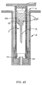
- the sixth embodiment of the present invention provides a safety syringe including a syringe barrel 2 with a different front-end wall 21.
- the front-end wall 21 includes a front opening 210' for fastening a needle 31, wherein the needle 31 projects from the front end wall 21.
- the holder-retaining front portion 51 is pushed to combine with the outward flange 303 when the plunger 4 is pushed to be close to the flexible holder-supporting seat 24.
- the piston body 521 contacts with the rear opening 300 to stuff the rear opening 300 to lock the needle 31 from injecting the medicament.
- the holder-retaining front portion 51 sleeves the outward flange 303 to combine with the needle unit 3 after the plunger 4 is continuously pushed to push the flexible holder-supporting seat 24, wherein the needle body 30 is propped by the spacer portion 212.
- the needle unit 3 is released from the flexible holder-supporting seat 24 when the flexible holder-supporting seat 24 does not contact with the needle unit 3.
- the flexible sealing member 5 stops moving due to the immovable needle body 30 and the piston body 521, and then the flexible sealing member 5 is released from the inward flange 44 because the plunger 4 is continuously pushed to push the flexible holder-supporting seat 24.
- the needle unit 3 combined with the flexible sealing member 5 and the piston body 521 is automatically retracted into the plunger body 40 due to the difference between two different pressures.
- the seventh embodiment of the present invention is illustrated as FIG. 9A and FIG. 9B.
- the difference between the fifth embodiment and the seventh embodiment of the present invention is the structure of the flexible sealing member 5.
- the flexible sealing member 5 includes a holder-retaining front portion 51, a sealing rear portion 52' and a curved projection 520', wherein the holder-retaining front portion 51 is a hollow awl extended forward from the hollow sealing rear portion 52'.
- the sealing rear portion 52' includes a hollow space therein.
- the external diameter of the holder-retaining front portion 51 is as small as that extending forward.
- the surface of the curved projection 520' is a cambered surface formed on the hollow sealing rear portion 52'.
- the holder-retaining front portion 51 is pushed to combine with the outward flange 303 when the plunger 4 is pushed forward to be close to the flexible holder-supporting seat 24 when the plunger 4 is pushed continuously.
- the inward flange 44 is still pushed forward to push the flexible holder-supporting seat 24, the curved projection 520' contacts with the rear opening 300 to stuff the rear opening 300 to prevent the needle 31 from injecting the medicament.
- the holder-retaining front portion 51 sleeves the outward flange 303 to combine with the needle unit 3 after the plunger 4 is pushed continuously to push the flexible holder-supporting seat 24, wherein the needle body 30 is propped by the spacer portion 212.
- the needle body 30 is released from the flexible holder-supporting seat 24 when the flexible holder-supporting seat 24 does not contact with the needle unit 3.
- the flexible sealing member 5 stops moving due to the immovable needle body 30 and is then released from the inward flange 44 because the plunger 4 is continuously pushed to push the flexible holder-supporting seat 24 and release the flexible sealing member 5.
- the needle unit 3 combined with the flexible sealing member 5 is automatically retracted into the plunger body 40 due to the difference between two different pressures.
- the eighth embodiment of the present invention provides a safety syringe including a syringe barrel 2 with a different front-end wall 21.
- the front-end wall 21 includes a front opening 210' for fastening a needle 31, wherein the needle 31 projects from the front end wall 21.
- the holder-retaining front portion 51 is pushed to sleeve and combine with the outward flange 303 when the plunger 4 is pushed to be close to the flexible holder-supporting seat 24.
- the inward flange 44 is still pushed forward to push the flexible holder-supporting seat 24, the curved projection 520' contacts with the rear opening 300 to stuff the rear opening 300 to prevent the needle 31 from injecting the medicament.
- the holder-retaining front portion 51 sleeves the outward flange 303 to combine with the needle unit 3 after the plunger 4 is continuously pushed to push the flexible holder-supporting seat 24, wherein the needle holder 302 is propped by the spacer portion 212.
- the needle unit 3 is released from the flexible holder-supporting seat 24 when the flexible holder-supporting seat 24 does not contact with the needle unit 3.
- the flexible sealing member 5 stops moving due to the immovable needle body 30, and then the flexible sealing member 5 is released from the inward flange 44 because the plunger 4 is continuously pushed to push the flexible holder-supporting seat 24.
- the needle unit 3 combined with the flexible sealing member 5 is automatically retracted into the plunger body 40 due to the difference between two different pressures.
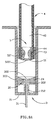
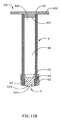
- the ninth embodiment of the present invention is illustrated as FIG. 11A to FIG. 11C.
- the difference between the ninth embodiment and the first embodiment of the present invention is the structure of the needle unit 3 and the flexible-sealing member 5.
- the needle unit 3 includes a needle holder 302 and a crook 304, wherein the crook 304 is fastened on the needle holder 302.
- the flexible sealing member 5 includes a sealing rear portion 52 and a curved projection 520, wherein the curved projection 520 is a cambered surface.
- An opening 523 is formed inside the sealing rear portion 52 for wedging the crook 304 of the needle body 30.
- FIG. 11A that the needle unit 3 includes a needle holder 302 and a crook 304, wherein the crook 304 is fastened on the needle holder 302.
- the flexible sealing member 5 includes a sealing rear portion 52 and a curved projection 520, wherein the curved projection 520 is a cambered surface.
- An opening 523
- the opening 523 of the sealing rear portion 52 is pushed to wedge the crook 304 for combining with the needle body 30 when the plunger 4 is pushed forward to be close to the flexible holder-supporting seat 24.
- the curved projection 520 contacts with the rear opening 300 to stuff the rear opening 300 to lock the needle 31 from injecting the medicament.
- the flexible sealing member 5 stops moving due to the immovable needle body 30 propped by the spacer portion 212, after the plunger 4 is continuously pushed to push the flexible holder-supporting seat 24.
- the needle body 30 is released from the flexible holder-supporting seat 24 when the flexible holder-supporting seat 24 does not contact with the needle unit 3.
- the flexible sealing member 5 stops moving due to the immovable needle body 30 and then is released from the inward flange 44 because the plunger 4 is continuously pushed to push the flexible holder-supporting seat 24 and release the flexible sealing member 5.
- the needle unit 3 combined with the flexible sealing member 5 is automatically retracted into the plunger body 40 due to the difference between two different pressures.
- the tenth embodiment of the present invention provides a safety syringe including a syringe barrel 2 with a different front-end wall 21.
- the front-end wall 21 includes a front opening 210 for fastening a needle 31, wherein the needle 31 projects from the front-end wall 21.
- the curved projection 520 is pushed to wedge the crook 304 and combine with the needle body 30 when the plunger 4 is pushed to be close to the flexible holder-supporting seat 24.
- the inward flange 44 is still pushed forward to push the flexible holder-supporting seat 24, the curved projection 520 contacts with the rear opening 300 to stuff the rear opening 300 to prevent the needle 31 from injecting the medicament.
- the flexible sealing member 5 stops moving due to the immovable needle body 30 propped by the spacer portion 212, after the plunger 4 is continuously pushed to push the flexible holder-supporting seat 24.
- the needle body 30 is released from the flexible holder-supporting seat 24 when the flexible holder-supporting seat 24 does not make contact with the needle body 30.
- the flexible sealing member 5 stops moving due to the immovable needle body 30, and then the flexible sealing member 5 is released from the inward flange 44 because the plunger 4 is continuously pushed to push the flexible holder-supporting seat 24.
- the needle unit 3 combined with the flexible sealing member 5 is automatically retracted into the plunger body 40 due to the difference between two different pressures.
- the present invention provides a safety syringe including simple elements.
- the present invention also economizes the cost for manufacturing the safety syringes and effectively protects the operating staff from becoming stabbed.
Landscapes
- Health & Medical Sciences (AREA)
- Engineering & Computer Science (AREA)
- Heart & Thoracic Surgery (AREA)
- Vascular Medicine (AREA)
- Anesthesiology (AREA)
- Biomedical Technology (AREA)
- Environmental & Geological Engineering (AREA)
- Hematology (AREA)
- Life Sciences & Earth Sciences (AREA)
- Animal Behavior & Ethology (AREA)
- General Health & Medical Sciences (AREA)
- Public Health (AREA)
- Veterinary Medicine (AREA)
- Infusion, Injection, And Reservoir Apparatuses (AREA)
Applications Claiming Priority (2)
| Application Number | Priority Date | Filing Date | Title |
|---|---|---|---|
| CN200310123297 | 2003-12-22 | ||
| CNB2003101232972A CN100382856C (zh) | 2003-12-22 | 2003-12-22 | 安全针筒 |
Publications (2)
| Publication Number | Publication Date |
|---|---|
| EP1547634A1 true EP1547634A1 (de) | 2005-06-29 |
| EP1547634B1 EP1547634B1 (de) | 2009-07-15 |
Family
ID=34529400
Family Applications (1)
| Application Number | Title | Priority Date | Filing Date |
|---|---|---|---|
| EP20040105886 Expired - Lifetime EP1547634B1 (de) | 2003-12-22 | 2004-11-18 | Sicherheitsspritze |
Country Status (4)
| Country | Link |
|---|---|
| EP (1) | EP1547634B1 (de) |
| JP (1) | JP4253295B2 (de) |
| CN (1) | CN100382856C (de) |
| DE (1) | DE602004022010D1 (de) |
Cited By (6)
| Publication number | Priority date | Publication date | Assignee | Title |
|---|---|---|---|---|
| WO2008055298A1 (en) | 2006-11-06 | 2008-05-15 | Simon Paul Clayson | Retractable syringe |
| WO2010100241A1 (en) * | 2009-03-05 | 2010-09-10 | Sanofi-Aventis Deutschland Gmbh | Drug delivery device with retractable needle |
| WO2010100240A1 (en) * | 2009-03-05 | 2010-09-10 | Sanofi-Aventis Deutschland Gmbh | Needle assembly |
| US20120116306A1 (en) * | 2009-03-05 | 2012-05-10 | Sanofi-Aventis Deutschland Gmbh | Needle unit |
| EP2000164A4 (de) * | 2006-03-28 | 2012-12-12 | Jianquan Li | Sich selbst zerstörende einwegspritze und selbstzerstörungsverfahren dafür |
| AU2007231844B2 (en) * | 2006-11-06 | 2013-05-30 | Clayson, Simon Paul Mr | Retractable Syringe |
Families Citing this family (6)
| Publication number | Priority date | Publication date | Assignee | Title |
|---|---|---|---|---|
| CN100581606C (zh) * | 2005-10-10 | 2010-01-20 | 王治明 | 安全针筒 |
| US8034024B2 (en) * | 2006-03-13 | 2011-10-11 | Medigard Limited | Needle containing medical device with variable locking to needle holder |
| AU2010317659B2 (en) * | 2009-11-11 | 2014-01-23 | Unitract Syringe Pty Ltd | Clinical syringe |
| TWI527602B (zh) * | 2011-11-07 | 2016-04-01 | Fan Xiao Yi | Ordinary safety syringes |
| US11298467B2 (en) * | 2019-02-27 | 2022-04-12 | Retractable Technologies, Inc. | Syringe with multifunctional needle holder and retainer ring assembly |
| CN113181499B (zh) * | 2021-06-02 | 2025-04-25 | 中国人民解放军联勤保障部队第九〇〇医院 | 一种枪伤辅助镇痛装置 |
Citations (5)
| Publication number | Priority date | Publication date | Assignee | Title |
|---|---|---|---|---|
| US6221055B1 (en) * | 1998-03-04 | 2001-04-24 | Retractable Technologies, Inc. | Retractable dental syringe |
| WO2001049348A2 (en) * | 2000-01-04 | 2001-07-12 | Becton, Dickinson And Company | Retracting needle syringe |
| US20030163094A1 (en) * | 2001-08-17 | 2003-08-28 | Chung-Yu Yang | Safety syringe |
| US20030212371A1 (en) * | 2002-05-10 | 2003-11-13 | Martin E. Smith | Disposable safety syringe |
| WO2004105842A1 (en) * | 2003-05-27 | 2004-12-09 | Nmt Group Plc | Syringes with restrictor |
-
2003
- 2003-12-22 CN CNB2003101232972A patent/CN100382856C/zh not_active Expired - Fee Related
-
2004
- 2004-11-18 EP EP20040105886 patent/EP1547634B1/de not_active Expired - Lifetime
- 2004-11-18 DE DE200460022010 patent/DE602004022010D1/de not_active Expired - Lifetime
- 2004-11-26 JP JP2004341642A patent/JP4253295B2/ja not_active Expired - Fee Related
Patent Citations (5)
| Publication number | Priority date | Publication date | Assignee | Title |
|---|---|---|---|---|
| US6221055B1 (en) * | 1998-03-04 | 2001-04-24 | Retractable Technologies, Inc. | Retractable dental syringe |
| WO2001049348A2 (en) * | 2000-01-04 | 2001-07-12 | Becton, Dickinson And Company | Retracting needle syringe |
| US20030163094A1 (en) * | 2001-08-17 | 2003-08-28 | Chung-Yu Yang | Safety syringe |
| US20030212371A1 (en) * | 2002-05-10 | 2003-11-13 | Martin E. Smith | Disposable safety syringe |
| WO2004105842A1 (en) * | 2003-05-27 | 2004-12-09 | Nmt Group Plc | Syringes with restrictor |
Cited By (13)
| Publication number | Priority date | Publication date | Assignee | Title |
|---|---|---|---|---|
| EP2000164A4 (de) * | 2006-03-28 | 2012-12-12 | Jianquan Li | Sich selbst zerstörende einwegspritze und selbstzerstörungsverfahren dafür |
| US8814827B2 (en) | 2006-11-06 | 2014-08-26 | Simon Paul Clayson | Retractable syringe |
| AU2007231844B2 (en) * | 2006-11-06 | 2013-05-30 | Clayson, Simon Paul Mr | Retractable Syringe |
| WO2008055298A1 (en) | 2006-11-06 | 2008-05-15 | Simon Paul Clayson | Retractable syringe |
| US20120116306A1 (en) * | 2009-03-05 | 2012-05-10 | Sanofi-Aventis Deutschland Gmbh | Needle unit |
| JP2012519509A (ja) * | 2009-03-05 | 2012-08-30 | サノフィ−アベンティス・ドイチュラント・ゲゼルシャフト・ミット・ベシュレンクテル・ハフツング | 後退可能な針を備えた薬物送達デバイス |
| US20120136318A1 (en) * | 2009-03-05 | 2012-05-31 | Sanofi-Aventis Deutschland Gmbh | Drug Delivery Device with Retractable Needle |
| WO2010100240A1 (en) * | 2009-03-05 | 2010-09-10 | Sanofi-Aventis Deutschland Gmbh | Needle assembly |
| WO2010100241A1 (en) * | 2009-03-05 | 2010-09-10 | Sanofi-Aventis Deutschland Gmbh | Drug delivery device with retractable needle |
| AU2010220255B2 (en) * | 2009-03-05 | 2014-09-04 | Sanofi-Aventis Deutschland Gmbh | Drug delivery device with retractable needle |
| AU2010220254B2 (en) * | 2009-03-05 | 2014-12-04 | Sanofi-Aventis Deutschland Gmbh | Needle assembly |
| US9216255B2 (en) | 2009-03-05 | 2015-12-22 | Sanofi-Aventis Deutschland Gmbh | Needle assembly |
| US9427530B2 (en) * | 2009-03-05 | 2016-08-30 | Sanofi-Aventis Deutschland Gmbh | Drug delivery device with retractable needle |
Also Published As
| Publication number | Publication date |
|---|---|
| CN1631460A (zh) | 2005-06-29 |
| CN100382856C (zh) | 2008-04-23 |
| JP2005177467A (ja) | 2005-07-07 |
| EP1547634B1 (de) | 2009-07-15 |
| DE602004022010D1 (de) | 2009-08-27 |
| JP4253295B2 (ja) | 2009-04-08 |
Similar Documents
| Publication | Publication Date | Title |
|---|---|---|
| US7410478B2 (en) | Safety syringe with needle retracting mechanism | |
| JP3002531B2 (ja) | 注射器 | |
| CN1909939B (zh) | 注射设备 | |
| JP2840867B2 (ja) | 安全注射器 | |
| CN100360196C (zh) | 一次使用后注射针能可靠缩回的一次性使用缩回式注射器 | |
| JP5938412B2 (ja) | 自動注射器のための再使用可能なエンジン | |
| EP1547634A1 (de) | Sicherheitsspritze | |
| HU225794B1 (en) | Disposable injection device | |
| KR20080113055A (ko) | 자체 파괴형의 일회용 주사기 및 그의 자체 파괴 방법 | |
| CN101547715A (zh) | 可缩回注射器 | |
| JP2006526443A (ja) | 使い捨て注射シリンジ | |
| JP4077836B2 (ja) | 安全注射器及びその操作方法 | |
| CN201030119Y (zh) | 自动回缩针头的安全注射器 | |
| US20080154213A1 (en) | Syringe with multiple plunger locks | |
| CN101068587B (zh) | 注射器 | |
| CN106659437B (zh) | 血液采样装置及相关方法 | |
| KR100249100B1 (ko) | 개선된 비경구장치 | |
| WO2003066144A1 (en) | A retractable non-reusable syringe | |
| KR20200059611A (ko) | 안전 필터 주사기의 작동구조 | |
| US8936570B2 (en) | Safety syringe | |
| JP4357000B2 (ja) | 使い捨て注射器用の安全インサート | |
| US20080161760A1 (en) | Medical Device Containing a Vacuum Chamber | |
| US8114051B2 (en) | Retractable syringe | |
| KR20050087697A (ko) | 주사기보호구조 | |
| KR20010067582A (ko) | 일회용 안전주사기 |
Legal Events
| Date | Code | Title | Description |
|---|---|---|---|
| PUAI | Public reference made under article 153(3) epc to a published international application that has entered the european phase |
Free format text: ORIGINAL CODE: 0009012 |
|
| 17P | Request for examination filed |
Effective date: 20041118 |
|
| AK | Designated contracting states |
Kind code of ref document: A1 Designated state(s): AT BE BG CH CY CZ DE DK EE ES FI FR GB GR HU IE IS IT LI LU MC NL PL PT RO SE SI SK TR |
|
| AX | Request for extension of the european patent |
Extension state: AL HR LT LV MK YU |
|
| AKX | Designation fees paid |
Designated state(s): AT BE BG CH CY CZ DE DK EE ES FI FR GB GR HU IE IS IT LI LU MC NL PL PT RO SE SI SK TR |
|
| 17Q | First examination report despatched |
Effective date: 20060130 |
|
| RAP1 | Party data changed (applicant data changed or rights of an application transferred) |
Owner name: CHUANG, CHUN-CHIEH Owner name: TSENG, HSI-HSUN Owner name: WANG, CHIH MING Owner name: LEE, PO-LIANG |
|
| RIN1 | Information on inventor provided before grant (corrected) |
Inventor name: YANG, CHUNG-YU |
|
| GRAP | Despatch of communication of intention to grant a patent |
Free format text: ORIGINAL CODE: EPIDOSNIGR1 |
|
| GRAS | Grant fee paid |
Free format text: ORIGINAL CODE: EPIDOSNIGR3 |
|
| GRAA | (expected) grant |
Free format text: ORIGINAL CODE: 0009210 |
|
| AK | Designated contracting states |
Kind code of ref document: B1 Designated state(s): AT BE BG CH CY CZ DE DK EE ES FI FR GB GR HU IE IS IT LI LU MC NL PL PT RO SE SI SK TR |
|
| REG | Reference to a national code |
Ref country code: GB Ref legal event code: FG4D Ref country code: CH Ref legal event code: EP |
|
| REG | Reference to a national code |
Ref country code: IE Ref legal event code: FG4D |
|
| REF | Corresponds to: |
Ref document number: 602004022010 Country of ref document: DE Date of ref document: 20090827 Kind code of ref document: P |
|
| NLV1 | Nl: lapsed or annulled due to failure to fulfill the requirements of art. 29p and 29m of the patents act | ||
| PG25 | Lapsed in a contracting state [announced via postgrant information from national office to epo] |
Ref country code: ES Free format text: LAPSE BECAUSE OF FAILURE TO SUBMIT A TRANSLATION OF THE DESCRIPTION OR TO PAY THE FEE WITHIN THE PRESCRIBED TIME-LIMIT Effective date: 20091026 Ref country code: FI Free format text: LAPSE BECAUSE OF FAILURE TO SUBMIT A TRANSLATION OF THE DESCRIPTION OR TO PAY THE FEE WITHIN THE PRESCRIBED TIME-LIMIT Effective date: 20090715 Ref country code: AT Free format text: LAPSE BECAUSE OF FAILURE TO SUBMIT A TRANSLATION OF THE DESCRIPTION OR TO PAY THE FEE WITHIN THE PRESCRIBED TIME-LIMIT Effective date: 20090715 Ref country code: IS Free format text: LAPSE BECAUSE OF FAILURE TO SUBMIT A TRANSLATION OF THE DESCRIPTION OR TO PAY THE FEE WITHIN THE PRESCRIBED TIME-LIMIT Effective date: 20091115 Ref country code: SE Free format text: LAPSE BECAUSE OF FAILURE TO SUBMIT A TRANSLATION OF THE DESCRIPTION OR TO PAY THE FEE WITHIN THE PRESCRIBED TIME-LIMIT Effective date: 20090715 |
|
| PGFP | Annual fee paid to national office [announced via postgrant information from national office to epo] |
Ref country code: DE Payment date: 20091126 Year of fee payment: 6 |
|
| PG25 | Lapsed in a contracting state [announced via postgrant information from national office to epo] |
Ref country code: SI Free format text: LAPSE BECAUSE OF FAILURE TO SUBMIT A TRANSLATION OF THE DESCRIPTION OR TO PAY THE FEE WITHIN THE PRESCRIBED TIME-LIMIT Effective date: 20090715 Ref country code: NL Free format text: LAPSE BECAUSE OF FAILURE TO SUBMIT A TRANSLATION OF THE DESCRIPTION OR TO PAY THE FEE WITHIN THE PRESCRIBED TIME-LIMIT Effective date: 20090715 Ref country code: PL Free format text: LAPSE BECAUSE OF FAILURE TO SUBMIT A TRANSLATION OF THE DESCRIPTION OR TO PAY THE FEE WITHIN THE PRESCRIBED TIME-LIMIT Effective date: 20090715 |
|
| PG25 | Lapsed in a contracting state [announced via postgrant information from national office to epo] |
Ref country code: PT Free format text: LAPSE BECAUSE OF FAILURE TO SUBMIT A TRANSLATION OF THE DESCRIPTION OR TO PAY THE FEE WITHIN THE PRESCRIBED TIME-LIMIT Effective date: 20091115 Ref country code: BG Free format text: LAPSE BECAUSE OF FAILURE TO SUBMIT A TRANSLATION OF THE DESCRIPTION OR TO PAY THE FEE WITHIN THE PRESCRIBED TIME-LIMIT Effective date: 20091015 |
|
| PG25 | Lapsed in a contracting state [announced via postgrant information from national office to epo] |
Ref country code: DK Free format text: LAPSE BECAUSE OF FAILURE TO SUBMIT A TRANSLATION OF THE DESCRIPTION OR TO PAY THE FEE WITHIN THE PRESCRIBED TIME-LIMIT Effective date: 20090715 Ref country code: EE Free format text: LAPSE BECAUSE OF FAILURE TO SUBMIT A TRANSLATION OF THE DESCRIPTION OR TO PAY THE FEE WITHIN THE PRESCRIBED TIME-LIMIT Effective date: 20090715 Ref country code: CZ Free format text: LAPSE BECAUSE OF FAILURE TO SUBMIT A TRANSLATION OF THE DESCRIPTION OR TO PAY THE FEE WITHIN THE PRESCRIBED TIME-LIMIT Effective date: 20090715 Ref country code: RO Free format text: LAPSE BECAUSE OF FAILURE TO SUBMIT A TRANSLATION OF THE DESCRIPTION OR TO PAY THE FEE WITHIN THE PRESCRIBED TIME-LIMIT Effective date: 20090715 |
|
| PLBE | No opposition filed within time limit |
Free format text: ORIGINAL CODE: 0009261 |
|
| STAA | Information on the status of an ep patent application or granted ep patent |
Free format text: STATUS: NO OPPOSITION FILED WITHIN TIME LIMIT |
|
| PG25 | Lapsed in a contracting state [announced via postgrant information from national office to epo] |
Ref country code: BE Free format text: LAPSE BECAUSE OF FAILURE TO SUBMIT A TRANSLATION OF THE DESCRIPTION OR TO PAY THE FEE WITHIN THE PRESCRIBED TIME-LIMIT Effective date: 20090715 Ref country code: SK Free format text: LAPSE BECAUSE OF FAILURE TO SUBMIT A TRANSLATION OF THE DESCRIPTION OR TO PAY THE FEE WITHIN THE PRESCRIBED TIME-LIMIT Effective date: 20090715 |
|
| 26N | No opposition filed |
Effective date: 20100416 |
|
| PG25 | Lapsed in a contracting state [announced via postgrant information from national office to epo] |
Ref country code: MC Free format text: LAPSE BECAUSE OF NON-PAYMENT OF DUE FEES Effective date: 20091130 |
|
| REG | Reference to a national code |
Ref country code: CH Ref legal event code: PL |
|
| GBPC | Gb: european patent ceased through non-payment of renewal fee |
Effective date: 20091118 |
|
| REG | Reference to a national code |
Ref country code: FR Ref legal event code: ST Effective date: 20100730 |
|
| PG25 | Lapsed in a contracting state [announced via postgrant information from national office to epo] |
Ref country code: GR Free format text: LAPSE BECAUSE OF FAILURE TO SUBMIT A TRANSLATION OF THE DESCRIPTION OR TO PAY THE FEE WITHIN THE PRESCRIBED TIME-LIMIT Effective date: 20091016 Ref country code: LI Free format text: LAPSE BECAUSE OF NON-PAYMENT OF DUE FEES Effective date: 20091130 Ref country code: IE Free format text: LAPSE BECAUSE OF NON-PAYMENT OF DUE FEES Effective date: 20091118 Ref country code: FR Free format text: LAPSE BECAUSE OF NON-PAYMENT OF DUE FEES Effective date: 20091130 Ref country code: CH Free format text: LAPSE BECAUSE OF NON-PAYMENT OF DUE FEES Effective date: 20091130 |
|
| PG25 | Lapsed in a contracting state [announced via postgrant information from national office to epo] |
Ref country code: GB Free format text: LAPSE BECAUSE OF NON-PAYMENT OF DUE FEES Effective date: 20091118 |
|
| PG25 | Lapsed in a contracting state [announced via postgrant information from national office to epo] |
Ref country code: IT Free format text: LAPSE BECAUSE OF FAILURE TO SUBMIT A TRANSLATION OF THE DESCRIPTION OR TO PAY THE FEE WITHIN THE PRESCRIBED TIME-LIMIT Effective date: 20090715 |
|
| PG25 | Lapsed in a contracting state [announced via postgrant information from national office to epo] |
Ref country code: LU Free format text: LAPSE BECAUSE OF NON-PAYMENT OF DUE FEES Effective date: 20091118 |
|
| PG25 | Lapsed in a contracting state [announced via postgrant information from national office to epo] |
Ref country code: HU Free format text: LAPSE BECAUSE OF FAILURE TO SUBMIT A TRANSLATION OF THE DESCRIPTION OR TO PAY THE FEE WITHIN THE PRESCRIBED TIME-LIMIT Effective date: 20100116 |
|
| PG25 | Lapsed in a contracting state [announced via postgrant information from national office to epo] |
Ref country code: TR Free format text: LAPSE BECAUSE OF FAILURE TO SUBMIT A TRANSLATION OF THE DESCRIPTION OR TO PAY THE FEE WITHIN THE PRESCRIBED TIME-LIMIT Effective date: 20090715 |
|
| REG | Reference to a national code |
Ref country code: DE Ref legal event code: R119 Ref document number: 602004022010 Country of ref document: DE Effective date: 20110601 Ref country code: DE Ref legal event code: R119 Ref document number: 602004022010 Country of ref document: DE Effective date: 20110531 |
|
| PG25 | Lapsed in a contracting state [announced via postgrant information from national office to epo] |
Ref country code: CY Free format text: LAPSE BECAUSE OF FAILURE TO SUBMIT A TRANSLATION OF THE DESCRIPTION OR TO PAY THE FEE WITHIN THE PRESCRIBED TIME-LIMIT Effective date: 20090715 |
|
| PG25 | Lapsed in a contracting state [announced via postgrant information from national office to epo] |
Ref country code: DE Free format text: LAPSE BECAUSE OF NON-PAYMENT OF DUE FEES Effective date: 20110531 |