EP1548202A2 - An insulating panel for building purposes - Google Patents
An insulating panel for building purposes Download PDFInfo
- Publication number
- EP1548202A2 EP1548202A2 EP04021538A EP04021538A EP1548202A2 EP 1548202 A2 EP1548202 A2 EP 1548202A2 EP 04021538 A EP04021538 A EP 04021538A EP 04021538 A EP04021538 A EP 04021538A EP 1548202 A2 EP1548202 A2 EP 1548202A2
- Authority
- EP
- European Patent Office
- Prior art keywords
- ribbing
- panel
- module
- ribbings
- sheet
- Prior art date
- Legal status (The legal status is an assumption and is not a legal conclusion. Google has not performed a legal analysis and makes no representation as to the accuracy of the status listed.)
- Granted
Links
Images


Classifications
-
- H—ELECTRICITY
- H02—GENERATION; CONVERSION OR DISTRIBUTION OF ELECTRIC POWER
- H02S—GENERATION OF ELECTRIC POWER BY CONVERSION OF INFRARED RADIATION, VISIBLE LIGHT OR ULTRAVIOLET LIGHT, e.g. USING PHOTOVOLTAIC [PV] MODULES
- H02S20/00—Supporting structures for PV modules
- H02S20/20—Supporting structures directly fixed to an immovable object
- H02S20/22—Supporting structures directly fixed to an immovable object specially adapted for buildings
- H02S20/23—Supporting structures directly fixed to an immovable object specially adapted for buildings specially adapted for roof structures
-
- E—FIXED CONSTRUCTIONS
- E04—BUILDING
- E04B—GENERAL BUILDING CONSTRUCTIONS; WALLS, e.g. PARTITIONS; ROOFS; FLOORS; CEILINGS; INSULATION OR OTHER PROTECTION OF BUILDINGS
- E04B7/00—Roofs; Roof construction with regard to insulation
- E04B7/12—Roofs; Roof construction with regard to insulation formed in bays, e.g. sawtooth roofs
-
- E—FIXED CONSTRUCTIONS
- E04—BUILDING
- E04D—ROOF COVERINGS; SKY-LIGHTS; GUTTERS; ROOF-WORKING TOOLS
- E04D3/00—Roof covering by making use of flat or curved slabs or stiff sheets
- E04D3/35—Roofing slabs or stiff sheets comprising two or more layers, e.g. for insulation
- E04D3/351—Roofing slabs or stiff sheets comprising two or more layers, e.g. for insulation at least one of the layers being composed of insulating material, e.g. fibre or foam material
- E04D3/352—Roofing slabs or stiff sheets comprising two or more layers, e.g. for insulation at least one of the layers being composed of insulating material, e.g. fibre or foam material at least one insulating layer being located between non-insulating layers, e.g. double skin slabs or sheets
-
- E—FIXED CONSTRUCTIONS
- E04—BUILDING
- E04D—ROOF COVERINGS; SKY-LIGHTS; GUTTERS; ROOF-WORKING TOOLS
- E04D3/00—Roof covering by making use of flat or curved slabs or stiff sheets
- E04D3/35—Roofing slabs or stiff sheets comprising two or more layers, e.g. for insulation
- E04D3/358—Roofing slabs or stiff sheets comprising two or more layers, e.g. for insulation with at least one of the layers being offset with respect to another layer
-
- F—MECHANICAL ENGINEERING; LIGHTING; HEATING; WEAPONS; BLASTING
- F24—HEATING; RANGES; VENTILATING
- F24S—SOLAR HEAT COLLECTORS; SOLAR HEAT SYSTEMS
- F24S25/00—Arrangement of stationary mountings or supports for solar heat collector modules
- F24S25/40—Arrangement of stationary mountings or supports for solar heat collector modules using plate-like mounting elements, e.g. profiled or corrugated plates; Plate-like module frames
-
- H—ELECTRICITY
- H02—GENERATION; CONVERSION OR DISTRIBUTION OF ELECTRIC POWER
- H02S—GENERATION OF ELECTRIC POWER BY CONVERSION OF INFRARED RADIATION, VISIBLE LIGHT OR ULTRAVIOLET LIGHT, e.g. USING PHOTOVOLTAIC [PV] MODULES
- H02S40/00—Components or accessories in combination with PV modules, not provided for in groups H02S10/00 - H02S30/00
- H02S40/30—Electrical components
- H02S40/34—Electrical components comprising specially adapted electrical connection means to be structurally associated with the PV module, e.g. junction boxes
-
- H—ELECTRICITY
- H02—GENERATION; CONVERSION OR DISTRIBUTION OF ELECTRIC POWER
- H02S—GENERATION OF ELECTRIC POWER BY CONVERSION OF INFRARED RADIATION, VISIBLE LIGHT OR ULTRAVIOLET LIGHT, e.g. USING PHOTOVOLTAIC [PV] MODULES
- H02S40/00—Components or accessories in combination with PV modules, not provided for in groups H02S10/00 - H02S30/00
- H02S40/30—Electrical components
- H02S40/36—Electrical components characterised by special electrical interconnection means between two or more PV modules, e.g. electrical module-to-module connection
-
- Y—GENERAL TAGGING OF NEW TECHNOLOGICAL DEVELOPMENTS; GENERAL TAGGING OF CROSS-SECTIONAL TECHNOLOGIES SPANNING OVER SEVERAL SECTIONS OF THE IPC; TECHNICAL SUBJECTS COVERED BY FORMER USPC CROSS-REFERENCE ART COLLECTIONS [XRACs] AND DIGESTS
- Y02—TECHNOLOGIES OR APPLICATIONS FOR MITIGATION OR ADAPTATION AGAINST CLIMATE CHANGE
- Y02B—CLIMATE CHANGE MITIGATION TECHNOLOGIES RELATED TO BUILDINGS, e.g. HOUSING, HOUSE APPLIANCES OR RELATED END-USER APPLICATIONS
- Y02B10/00—Integration of renewable energy sources in buildings
- Y02B10/10—Photovoltaic [PV]
-
- Y—GENERAL TAGGING OF NEW TECHNOLOGICAL DEVELOPMENTS; GENERAL TAGGING OF CROSS-SECTIONAL TECHNOLOGIES SPANNING OVER SEVERAL SECTIONS OF THE IPC; TECHNICAL SUBJECTS COVERED BY FORMER USPC CROSS-REFERENCE ART COLLECTIONS [XRACs] AND DIGESTS
- Y02—TECHNOLOGIES OR APPLICATIONS FOR MITIGATION OR ADAPTATION AGAINST CLIMATE CHANGE
- Y02B—CLIMATE CHANGE MITIGATION TECHNOLOGIES RELATED TO BUILDINGS, e.g. HOUSING, HOUSE APPLIANCES OR RELATED END-USER APPLICATIONS
- Y02B10/00—Integration of renewable energy sources in buildings
- Y02B10/20—Solar thermal
-
- Y—GENERAL TAGGING OF NEW TECHNOLOGICAL DEVELOPMENTS; GENERAL TAGGING OF CROSS-SECTIONAL TECHNOLOGIES SPANNING OVER SEVERAL SECTIONS OF THE IPC; TECHNICAL SUBJECTS COVERED BY FORMER USPC CROSS-REFERENCE ART COLLECTIONS [XRACs] AND DIGESTS
- Y02—TECHNOLOGIES OR APPLICATIONS FOR MITIGATION OR ADAPTATION AGAINST CLIMATE CHANGE
- Y02E—REDUCTION OF GREENHOUSE GAS [GHG] EMISSIONS, RELATED TO ENERGY GENERATION, TRANSMISSION OR DISTRIBUTION
- Y02E10/00—Energy generation through renewable energy sources
- Y02E10/40—Solar thermal energy, e.g. solar towers
- Y02E10/47—Mountings or tracking
-
- Y—GENERAL TAGGING OF NEW TECHNOLOGICAL DEVELOPMENTS; GENERAL TAGGING OF CROSS-SECTIONAL TECHNOLOGIES SPANNING OVER SEVERAL SECTIONS OF THE IPC; TECHNICAL SUBJECTS COVERED BY FORMER USPC CROSS-REFERENCE ART COLLECTIONS [XRACs] AND DIGESTS
- Y02—TECHNOLOGIES OR APPLICATIONS FOR MITIGATION OR ADAPTATION AGAINST CLIMATE CHANGE
- Y02E—REDUCTION OF GREENHOUSE GAS [GHG] EMISSIONS, RELATED TO ENERGY GENERATION, TRANSMISSION OR DISTRIBUTION
- Y02E10/00—Energy generation through renewable energy sources
- Y02E10/50—Photovoltaic [PV] energy
Definitions
- the present invention relates to the sector of insulating panels for the building industry.
- the structure of said panels typically consists of a layer of insulating material, for example, fibreglass or polyurethane resin, set between two metal sheets. Said structure must enable a good modularity to be achieved, understood as the possibility of coupling a number of panels to one another to obtain a continuous covering surface.
- the panels are usually rectangular and are prearranged for being coupled alongside one another, along the respective long sides. Said structure must moreover enable panels to be made of dimensions very different from one another, without causing thereby significant modifications in the production cycle, which is preferably a cycle of a continuous type.
- photovoltaic devices are based upon the capacity of some appropriately treated semiconductor materials (for example, silicon) for converting the energy of solar radiation into d.c. electrical energy, without any need for mechanical parts in motion.
- semiconductor materials for example, silicon
- the basic component of a photovoltaic system is the photovoltaic cell, and a number of cells assembled and connected together in a single structure form a photovoltaic module.
- the most common modules consist of 36 cells connected in series, assembled between a top layer of glass and a bottom layer of plastic material (usually Tedlar), and enclosed within a metal frame, usually made of anodized aluminium.
- junction box in which electrical components, such as diodes, fuses, overload-protection systems, etc., are housed, as well as contacts or terminals for electrical connection of a number of modules in series or in parallel.
- electrical components such as diodes, fuses, overload-protection systems, etc.
- the transfer of energy from the photovoltaic system to the electrical loads usually occurs through additional devices, necessary, for example, for accumulating, transforming, and/or adapting the direct current produced by the photovoltaic modules to the requirements of the end user.
- the various photovoltaic modules necessary for formation of the generator call for an adequate supporting framework, the components of which must, for example, be designed according to the characteristics of the roof. Once made, said components must be assembled together, in order to obtain the framework, and anchored on the roof. This is followed by the installation of the various modules on the framework, as well as the execution of the necessary electrical connections of the various modules in series or in parallel.
- the present invention proposes the solution of one or more of the drawbacks referred to above, in a simple, inexpensive, and efficient way.
- an insulating panel for the building industry by a system for the construction of external surfaces of buildings, and by a method for the construction of external surfaces of buildings having the characteristics specified in the annexed claims, which are to be understood as forming an integral part of the present description.
- the reference number 1 designates as a whole a generic building, which is herein supposed as being an industrial shed.
- the building 1 has side surfaces or walls, designated by 2, and a typical shed roof 3, i.e., one formed by a succession of double-pitch roofs, of which one pitch is inclined and the other is close to the vertical.
- the inclined pitches are coated or formed by prefabricated insulating panels of a substantially known type, designated by 4, and prefabricated insulating panels built in accordance with the invention, designated by 5.
- the panels 4 and 5 are mounted alongside one another, i.e., side by side.
- the longitudinal development of the panels 4, 5 is continuous, in the sense that each of them extends substantially from the ridge of the roof as far as the bottom edge of the respective inclined pitch.
- the means for making the sealed side joint between the panels 4, 5, as well as the means for forming the anchorage in position of the panels themselves are not represented and described herein, in so far as they are of a conception in itself known.
- Figure 2 represents, in cross-sectional view, a panel 4, the structure of which is preferably formed by a bottom metal sheet 6 and a top metal sheet 7, between which there is set a layer or mass of insulating or non-conducting material 8.
- the layer 8 can be made, for example, of self-extinguishing polyurethane resin or polyisocyanide foam or with flame-retardant additive.
- the very bonding capacity of the foamed material used can be advantageously exploited for fixing together the cited components 6-8 of the panel 4 in order to obtain a substantially monolithic structure and thus eliminate the need for welded or mechanical connections.
- Both of the sheets 6 and 7 can be obtained via rolling starting from sheet metal, for example made of stainless or galvanized steel, or made of aluminium or copper, possibly painted or subjected to other forms of surface treatment.
- the sheets 6 and 7 are corrugated; i.e., they have parallel ribbings in a longitudinal direction, which extend substantially throughout the length of the sheets themselves.
- parallel longitudinal ribbings which are equal to one another, designated by 9.
- the panel 4 envisages three deep ribbings, designated by 10A, 10B and 10C, having a substantially trapezoidal cross-sectional shape, whilst the shallow ribbings, designated by 11 have a prevalently semicircular cross section, where, between two deep ribbings there extends a plurality of shallow ribbings in the same longitudinal direction.
- the sheets 6, 7 are shaped for "closing" laterally the space designed for containing the insulating mass 8. At one end of the panel 4, the sheet 7 is shaped for forming part of a deep ribbing 10A outside said space; note that said external ribbing could be formed by the sheet 6.
- the panels 5 are conceived for integrating one or more photovoltaic modules.
- Figure 3 represents a schematic cross section of a panel 5.
- the basic structure of said panel 5 is obtained substantially adopting modalities similar to the ones previously described with reference to the panel 4 of Figure 2. Consequently, in the following figures the same reference numbers as the ones appearing in Figure 2 will be used to designate elements that are technically equivalent to the ones already described, with the addition of the prime superscript.
- the panel 5 has a structure preferably formed by a bottom metal sheet 6' and a top metal sheet 7', between which is set a layer of insulating or non-conducting material 8'.
- a respective longitudinal projection or corrugation 12 in the course of forming or shaping of the top sheet 7', in a position corresponding to each inclined side of the central deep ribbing 10B' there is formed a respective longitudinal projection or corrugation 12.
- similar projections 12 are formed in the inclined sides of the side ribbings 10A' and 10C' facing the central ribbing 10B'.
- the projections 12 have a substantially triangular cross section, with one side set horizontal, which forms a sort of bracket or cantilever.
- a duct or piping for example consisting of a tube made of plastic material designated by 13.
- the aforesaid "cantilever" projections 12 constitute areas of resting for opposite side edges of the photovoltaic modules, designated as a whole by 14 in Figures 1, 3 and 4.
- Said modules 14 are built in a way in itself known, as explained in the introductory part of the present description, for example comprising a plurality of photovoltaic cells connected in series, assembled between a top layer made of transparent material and a bottom layer made of plastic material, and enclosed by a metal frame, designated by 14A.
- a junction box designated by 14B.
- the position of the projections 12 is such that the modules 14 are raised with respect to the general plane of the sheet, i.e., with respect to the plane of the areas in which the shallow ribbings 11' are formed.
- the modules 14, the deep ribbings 10A', 10B', 10C', and the part of the sheet 7' that extends between the ribbings themselves delimit ventilation chambers, designated by 15, within which there are located also the junction boxes 14A of each module 14.
- the peripheral frame 14A is designed to remain resting on the horizontal surface of the respective projection 12.
- a bracket 16 for clamping the module 14 to the panel 5, with possible interposition of a gasket or resilient element G.
- Fixing of the bracket 16 may be obtained using self-threading screws (not represented), with suitable seal gaskets or with subsequent apposition of sealing material, preferably in areas of the respective ribbing 10A', 10B', 10C' not close to the position of the tube 13.
- a substantial advantage afforded by the present invention is constituted by the fact that the panels 5 equipped with the respective photovoltaic modules 14 can be fabricated completely in the factory.
- the metal structure of a panel 5 so that in the space delimited between the sheets 6', 7', and in particular within the projections 12, there is positioned the tube 13, previously obtained from plastic material. Said space is subsequently "foamed", or in any case filled with the insulating mass 8', which maintains in position the tube 13 within the respective projection 12.
- suitable points of the panel 5 there are subsequently formed holes for installation of cable-leads or glands or similar substantially tubular seal members, of a type in itself known, one of which is designated by 17 in Figure 4.
- the aforesaid holes are formed in the sheet 7', in a position corresponding to a projection 12, and in the wall of the tube 13 so as to be able to fix a respective gland or cable-lead 17.
- the number and the disposition of the cable-leads 17 will depend upon the number and upon the position of the modules 14 that are mounted on of a single panel 5. It should, however, be borne in mind that one and the same cable-lead 17 can be exploited for the passage of the electrical cables for a number of panels. In the cable-leads 17 there are then inserted the cables designed to be connected to a respective junction box 14B.
- each of said cables (one of which is designated by 18 in Figure 4) is connected to the respective box 14B, whilst the other end is made to come out of the end of the tube 13 that is set in a position corresponding to one longitudinal end of the respective panel 5, for example as may be seen schematically in Figure 5.
- the module or modules 14 provided for the panel 5 are positioned on the respective projections 12 and fixed thereto in position, as previously explained, via the brackets 16.
- the panel 5 is formed and comprises a monolithic structure, consisting of the sheets 6', 7' and the respective insulating mass 8', with associated thereto one or more photovoltaic modules 14, the wiring 18 of which passes in the pipe present in the insulating core and is ready for connection in series or in parallel according to the needs.
- the panel 5 will be equipped, at the respective longitudinal ends, with endpieces or, in any case, with suitable complements for closing the internal space in which there is present the insulating mass 8'.
- One such closing complement is schematized in Figure 1 and designated by the reference number 19.
- At least one of said complements 19 will be equipped with one or more cable-leads 17', mounted in a position corresponding to one end of a respective tube 13, in order to enable exit of the relevant wiring 18 of the various modules 14 mounted on the respective panel, as schematized in Figure 1.
- a substantial advantage of the invention lies in the fact that the panel 5, equipped with the respective modules 14, can be entirely built and assembled in the factory. There are consequently evident the advantages in terms of working safety and quality.
- the operator who pre-arranges the modules 14 on the panel 5 can in fact operate in optimal conditions and in complete tranquillity, since he is not on the roof of a building or in any case in conditions of potential danger, it thus being possible for him to devote his complete attention to the pre-arrangement of the panel 5.
- the panel 5 Once the panel 5 has been obtained as described previously, it can finally be transported onto the building site and then mounted in order to obtain the desired pitches, with modalities altogether similar to the ones adopted for the installation of the panels 4 of a known type.
- the panels 4, 5 are mounted alongside one another, i.e., side by side, as represented in Figure 1.
- anchorage of the panels 4, 5 with respect to the underlying structure of the building 1 can be obtained with methodologies and means in themselves known, such as the longitudinal sealing joint between the panels.
- the ribbing 10A, 10A' of a panel 4, 5 will be fitted on the ribbing 10C, 10C' of the adjacent panel 4, 5.
- the covering or roof can finally be completed at the side ends of the panels 4, 5 via suitable complements, such as the endpieces 19, or suitable sealing borders, edgings, or gutters.
- the panels 5 are mounted alternately with traditional panels 4. This possibility is obviously provided, purely by way of example, in so far as nothing prevents making entire areas of a roof, or, even, the entire roof, using only the panels 5.
- the various cables 18 at output therefrom will be guided via suitable ducts or guides associated to the structure of the building, which are not represented in so far as they are of a type in itself known, up to a respective point for connection, for example with an electrical load, or with an accumulator, or with an inverter, etc.
- Said aspects, which pertain prevalently to the construction of the electrical wiring system of the building 1, are irrespective of the purposes of the present invention and consequently are not described herein.
- FIGS 5 and 6 illustrate a possible variant embodiment of the invention, in accordance with which the ribbings 10A', 10B', 10C' are shaped for defining grooves or throats 12', instead of projections 12.
- Said figures use the reference numbers of the preceding figures to indicate elements that are technically equivalent to the ones already described previously.
- the modules 14 are mounted on the panel 5 by inserting the opposite edges of the respective frames 14A into the grooves 12', which basically form seats, in which the opposite edges of the modules themselves can be made to slide until the desired position is reached. Fixing in position of the modules can then occur with modalities in themselves known, for example via clamping members of a known type, for instance screw-operated self-centring clamping members, mounted directly within the grooves 12', in a position corresponding to the two longitudinal ends of the module 14, or else via external elements or brackets.
- the positioning grooves 12' can be obtained in the course of the step of shaping of the sheets 6', 7'.
- construction of the panel 5 integrating the photovoltaic modules 14 is obtained adopting modalities similar to the ones described previously.
- the panel 5 is equipped with a single tube 13, in a position corresponding to the central ribbing 10B', on which there will be installed the cable-leads 17 for the cables 18 of the modules 14 mounted on the right and on the left of the ribbing itself.
- the tube 13 is positioned underneath and substantially tangentially with respect to the grooves 12', with the cable-leads 17 directly facing or projecting into the two chambers 15 of the panel 5 represented.
- the tube 13 could in any case be positioned between the two channels 12' of the ribbing 10B' and/or substantially adjacent to the top wall of a deep ribbing.
- a tube 13' represented by dashed lines is set within the ribbing 10C', in a position corresponding to its top, and is mounted on the latter passing through a single cable-lead 17", which is also represented hatched.
- the cables 18 coming from the box 14B can reach the cable-lead 17" passing through a minimal gap left between the longitudinal ends of adjacent modules 14.
- the component 5 described is a covering panel, which can be numbered amongst monolithic prefabricated modular components, equipped with one or more respective photovoltaic units 14 already in position and provided with respective cables for connection, ready for installation.
- the structure of the panel 5 described in addition to being simple and hence of contained cost, enables a considerable degree of modularity, understood as the possibility of associating a number of panels to one another to obtain a continuous covering.
- the system of construction proposed likewise enables panels of dimensions that may be different from one another to be obtained, without this causing substantial variations in the production cycle, which may thus be a cycle of continuous processing.
- the panels 5 may be obtained, in the course of the production process, of the desired length according to the specific requirements of the end user, and can then be equipped with a number of modules 14 depending upon the requirements of the user himself.
- the panels 5 do not constitute a mere support for the modules 14, but themselves form a roof and at the same time, if so desired, a false ceiling for the building (in which case the respective sheets 6' will be painted or surface treated).
- a tube 13 is set in a position corresponding to each projection 12 of the ribbings 10A', 10B', 10C'. It is, however, clear that the panel 5 could envisage just two tubes 13, for example each in a position corresponding to a side ribbing 10A', 10C' or else both in a position corresponding to the central ribbing 10B', or even a single tube 13, in a position corresponding to the central ribbing 10B', as in the case of Figure 5 or Figure 6. As has been said, the tube 13 must not necessarily have to be set in a position corresponding to a projection 12.
- the tubes 13 could even be omitted, in which case the ducts for the passage of the cables 18 could be formed directly by an area of a respective ribbing, in particular a projection 12. Also this possibility is exemplified schematically in Figure 4, where the reference number 20 designates a possible additional wall, formed for example by a suitable adhesive tape.
- the projection 12 is closed longitudinally via the tape 20.
- the insulating mass 8' for example in the form of foam, which thus fills every interstice, with the exception of the area designated by 21, which can then be exploited as pipe for the passage of the cables 18.
- the ribbings 10A', 10B', 10C' are built via continuous shaping of the respective sheet metal. Moreover, nothing prevents making said ribbings and/or the respective projections 12 or channels 12' in another way, for example via processes of pressing or drawing or other mechanical deformation executed on the sheets 6', 7'.
- the shape of the deep ribbings could be obviously different from the trapezoidal one exemplified previously.
- the insulating or non-conducting material 8 could be made of mineral fibre, rather than of a layer of foamed material, and the bottom sheet 6' could be made of a non-metallic rigid or semi-rigid material, for example asphaltic-felt roofing, plastic reinforced with fibreglass, or fibreglass.
- the application of the invention must not be understood as limited to the use of the panels 5 for the purposes of constructing roofing, it being possible for the panels themselves to be in fact used for covering or forming surfaces or side walls of buildings.
- the panels 5 can of course be used also for the purposes of constructing roofs different from what is illustrated by way of example in Figure 1, such as for example flat roofs, single-pitch roofs, double-pitch roofs, etc.
- the module or modules 14 mounted on a panel 5 may not occupy the entire longitudinal development of the panel itself.
Landscapes
- Engineering & Computer Science (AREA)
- Architecture (AREA)
- Civil Engineering (AREA)
- Structural Engineering (AREA)
- Physics & Mathematics (AREA)
- Thermal Sciences (AREA)
- Sustainable Development (AREA)
- Sustainable Energy (AREA)
- Life Sciences & Earth Sciences (AREA)
- Chemical & Material Sciences (AREA)
- Combustion & Propulsion (AREA)
- Mechanical Engineering (AREA)
- General Engineering & Computer Science (AREA)
- Electromagnetism (AREA)
- Roof Covering Using Slabs Or Stiff Sheets (AREA)
- Panels For Use In Building Construction (AREA)
Abstract
Description
- The present invention relates to the sector of insulating panels for the building industry.
- For the purposes of covering or constructing external surfaces of buildings there are widely used components in the form of modular panels that can be put together, which must present good characteristics of tightness to infiltration, thermal insulation and mechanical resistance. The structure of said panels typically consists of a layer of insulating material, for example, fibreglass or polyurethane resin, set between two metal sheets. Said structure must enable a good modularity to be achieved, understood as the possibility of coupling a number of panels to one another to obtain a continuous covering surface. For this purpose, the panels are usually rectangular and are prearranged for being coupled alongside one another, along the respective long sides. Said structure must moreover enable panels to be made of dimensions very different from one another, without causing thereby significant modifications in the production cycle, which is preferably a cycle of a continuous type.
- The interest in renewable energy sources has in recent times assumed increasing importance, above all with reference to the exploitation of solar energy via photovoltaic devices. As is known, the operation of photovoltaic devices is based upon the capacity of some appropriately treated semiconductor materials (for example, silicon) for converting the energy of solar radiation into d.c. electrical energy, without any need for mechanical parts in motion. The basic component of a photovoltaic system is the photovoltaic cell, and a number of cells assembled and connected together in a single structure form a photovoltaic module. The most common modules consist of 36 cells connected in series, assembled between a top layer of glass and a bottom layer of plastic material (usually Tedlar), and enclosed within a metal frame, usually made of anodized aluminium. The structure thus formed is strong and is able to guarantee many years of operation. In the rear part of the module there is usually located a so-called junction box, in which electrical components, such as diodes, fuses, overload-protection systems, etc., are housed, as well as contacts or terminals for electrical connection of a number of modules in series or in parallel. According to the voltage desired for the system, a number of modules can be connected in series, in a so-called "string". The electric power requirement then determines the number of strings to be connected in parallel for providing a photovoltaic generator. The transfer of energy from the photovoltaic system to the electrical loads usually occurs through additional devices, necessary, for example, for accumulating, transforming, and/or adapting the direct current produced by the photovoltaic modules to the requirements of the end user. An essential component in this sense, if, that is, the loads have to be supplied with alternating current, is the inverter, a device that converts the direct current at output from the photovoltaic generator into alternating current.
- At the current state of the art, the provision of a photovoltaic generator on surfaces of a building formed using prefabricated insulating panels of the type referred to previously entails some problems.
- In the first place, the various photovoltaic modules necessary for formation of the generator call for an adequate supporting framework, the components of which must, for example, be designed according to the characteristics of the roof. Once made, said components must be assembled together, in order to obtain the framework, and anchored on the roof. This is followed by the installation of the various modules on the framework, as well as the execution of the necessary electrical connections of the various modules in series or in parallel.
- The consequence of said known art is that the operations necessary for installation and anchorage of the framework, for installation of the various modules on the framework, and for electrical connection of the modules must be performed directly on the roof of the building, or in any case in sub-optimal working conditions and frequently in conditions of potential danger. The fact that the persons responsible for carrying out installation find themselves operating in such critical conditions is detrimental to the speed and quality of pre-arrangement of the system. This results basically in an increase in the times and overall costs of installation of the photovoltaic system.
- In its general terms, the present invention proposes the solution of one or more of the drawbacks referred to above, in a simple, inexpensive, and efficient way.
- The above and other purposes are achieved, according to the present invention, by an insulating panel for the building industry, by a system for the construction of external surfaces of buildings, and by a method for the construction of external surfaces of buildings having the characteristics specified in the annexed claims, which are to be understood as forming an integral part of the present description.
- Further purposes, characteristics and advantages of the present invention will emerge clearly from the ensuing detailed description and from the annexed drawings, which is provided purely by way of explanatory and non-limiting example and in which:
- Figure 1 is a partial perspective view of a generic building, with a top covering which uses insulating panels built according to the teachings of the present invention;
- Figure 2 is a schematic cross-sectional view of an insulating panel of a known type;
- Figure 3 is a partially exploded schematic cross-sectional view of an insulating panel according to the invention;
- Figure 4 is a partial and schematic cross-sectional view, at an enlarged scale with respect to Figure 3, of an insulating panel according to the invention;
- Figure 5 is a schematic, perspective, and partially cross-sectional view of an insulating panel built in accordance with a first variant of the invention; and
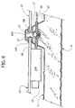
- Figure 6 is a schematic, perspective, and partially cross-sectional view of an insulating panel built in accordance with a second variant of the invention.
- In Figure 1, the reference number 1 designates as a whole a generic building, which is herein supposed as being an industrial shed. The building 1 has side surfaces or walls, designated by 2, and a
typical shed roof 3, i.e., one formed by a succession of double-pitch roofs, of which one pitch is inclined and the other is close to the vertical. The inclined pitches are coated or formed by prefabricated insulating panels of a substantially known type, designated by 4, and prefabricated insulating panels built in accordance with the invention, designated by 5. - The
panels panels panels - Figure 2 represents, in cross-sectional view, a
panel 4, the structure of which is preferably formed by abottom metal sheet 6 and atop metal sheet 7, between which there is set a layer or mass of insulating ornon-conducting material 8. Thelayer 8 can be made, for example, of self-extinguishing polyurethane resin or polyisocyanide foam or with flame-retardant additive. The very bonding capacity of the foamed material used can be advantageously exploited for fixing together the cited components 6-8 of thepanel 4 in order to obtain a substantially monolithic structure and thus eliminate the need for welded or mechanical connections. - Both of the
sheets sheets bottom sheet 6, in the latter there can be defined parallel longitudinal ribbings, which are equal to one another, designated by 9. Likewise, in the course of shaping of thetop sheet 7, there are defined, in the latter, deep longitudinal ribbings and shallow longitudinal ribbings, which rise from a general plane of the sheet itself so that the top surface of thepanel 4 presents a recurrent pattern. In the case exemplified, thepanel 4 envisages three deep ribbings, designated by 10A, 10B and 10C, having a substantially trapezoidal cross-sectional shape, whilst the shallow ribbings, designated by 11 have a prevalently semicircular cross section, where, between two deep ribbings there extends a plurality of shallow ribbings in the same longitudinal direction. - Even though this is not strictly indispensable for the purposes of the construction of a
panel 4, in the case exemplified in Figure 2 thesheets insulating mass 8. At one end of thepanel 4, thesheet 7 is shaped for forming part of a deep ribbing 10A outside said space; note that said external ribbing could be formed by thesheet 6. - According to an important aspect of the present invention, the
panels 5 are conceived for integrating one or more photovoltaic modules. - Figure 3 represents a schematic cross section of a
panel 5. The basic structure of saidpanel 5 is obtained substantially adopting modalities similar to the ones previously described with reference to thepanel 4 of Figure 2. Consequently, in the following figures the same reference numbers as the ones appearing in Figure 2 will be used to designate elements that are technically equivalent to the ones already described, with the addition of the prime superscript. - Also the
panel 5 has a structure preferably formed by a bottom metal sheet 6' and a top metal sheet 7', between which is set a layer of insulating or non-conducting material 8'. - In the case exemplified, in the course of forming or shaping of the top sheet 7', in a position corresponding to each inclined side of the central deep ribbing 10B' there is formed a respective longitudinal projection or
corrugation 12. In the embodiment represented,similar projections 12 are formed in the inclined sides of theside ribbings 10A' and 10C' facing the central ribbing 10B'. Once again in the case exemplified, and as may be seen in detail also in Figure 4, theprojections 12 have a substantially triangular cross section, with one side set horizontal, which forms a sort of bracket or cantilever. Within eachprojection 12 there is present a duct or piping, for example consisting of a tube made of plastic material designated by 13. - The aforesaid "cantilever"
projections 12 constitute areas of resting for opposite side edges of the photovoltaic modules, designated as a whole by 14 in Figures 1, 3 and 4. Saidmodules 14 are built in a way in itself known, as explained in the introductory part of the present description, for example comprising a plurality of photovoltaic cells connected in series, assembled between a top layer made of transparent material and a bottom layer made of plastic material, and enclosed by a metal frame, designated by 14A. In the rear part of each module there is provided a junction box, designated by 14B. - The position of the
projections 12 is such that themodules 14 are raised with respect to the general plane of the sheet, i.e., with respect to the plane of the areas in which theshallow ribbings 11' are formed. In this way, themodules 14, thedeep ribbings 10A', 10B', 10C', and the part of the sheet 7' that extends between the ribbings themselves delimit ventilation chambers, designated by 15, within which there are located also thejunction boxes 14A of eachmodule 14. - As may be seen in Figure 4, the
peripheral frame 14A is designed to remain resting on the horizontal surface of therespective projection 12. To the respective deep ribbing, in the case exemplified at the top of the ribbing 10C', there is then fixed abracket 16 for clamping themodule 14 to thepanel 5, with possible interposition of a gasket or resilient element G. Fixing of thebracket 16 may be obtained using self-threading screws (not represented), with suitable seal gaskets or with subsequent apposition of sealing material, preferably in areas of the respective ribbing 10A', 10B', 10C' not close to the position of thetube 13. - A substantial advantage afforded by the present invention is constituted by the fact that the
panels 5 equipped with the respectivephotovoltaic modules 14 can be fabricated completely in the factory. For said purpose, there is first formed the metal structure of apanel 5, so that in the space delimited between the sheets 6', 7', and in particular within theprojections 12, there is positioned thetube 13, previously obtained from plastic material. Said space is subsequently "foamed", or in any case filled with the insulating mass 8', which maintains in position thetube 13 within therespective projection 12. In suitable points of thepanel 5 there are subsequently formed holes for installation of cable-leads or glands or similar substantially tubular seal members, of a type in itself known, one of which is designated by 17 in Figure 4. In the case of Figure 4, the aforesaid holes are formed in the sheet 7', in a position corresponding to aprojection 12, and in the wall of thetube 13 so as to be able to fix a respective gland or cable-lead 17. Obviously, the number and the disposition of the cable-leads 17 will depend upon the number and upon the position of themodules 14 that are mounted on of asingle panel 5. It should, however, be borne in mind that one and the same cable-lead 17 can be exploited for the passage of the electrical cables for a number of panels. In the cable-leads 17 there are then inserted the cables designed to be connected to arespective junction box 14B. One end of each of said cables (one of which is designated by 18 in Figure 4) is connected to therespective box 14B, whilst the other end is made to come out of the end of thetube 13 that is set in a position corresponding to one longitudinal end of therespective panel 5, for example as may be seen schematically in Figure 5. At this point, the module ormodules 14 provided for thepanel 5 are positioned on therespective projections 12 and fixed thereto in position, as previously explained, via thebrackets 16. At this point, then, thepanel 5 is formed and comprises a monolithic structure, consisting of the sheets 6', 7' and the respective insulating mass 8', with associated thereto one or morephotovoltaic modules 14, thewiring 18 of which passes in the pipe present in the insulating core and is ready for connection in series or in parallel according to the needs. - Subsequently, for example in the installation stage, the
panel 5 will be equipped, at the respective longitudinal ends, with endpieces or, in any case, with suitable complements for closing the internal space in which there is present the insulating mass 8'. One such closing complement is schematized in Figure 1 and designated by thereference number 19. At least one of said complements 19 will be equipped with one or more cable-leads 17', mounted in a position corresponding to one end of arespective tube 13, in order to enable exit of therelevant wiring 18 of thevarious modules 14 mounted on the respective panel, as schematized in Figure 1. - As may be appreciated, a substantial advantage of the invention lies in the fact that the
panel 5, equipped with therespective modules 14, can be entirely built and assembled in the factory. There are consequently evident the advantages in terms of working safety and quality. The operator who pre-arranges themodules 14 on thepanel 5 can in fact operate in optimal conditions and in complete tranquillity, since he is not on the roof of a building or in any case in conditions of potential danger, it thus being possible for him to devote his complete attention to the pre-arrangement of thepanel 5. Once thepanel 5 has been obtained as described previously, it can finally be transported onto the building site and then mounted in order to obtain the desired pitches, with modalities altogether similar to the ones adopted for the installation of thepanels 4 of a known type. - For the purposes of covering or obtaining inclined pitches of the building 1, the
panels panels ribbing panel ribbing adjacent panel panels endpieces 19, or suitable sealing borders, edgings, or gutters. In the case exemplified in Figure 1, thepanels 5 are mounted alternately withtraditional panels 4. This possibility is obviously provided, purely by way of example, in so far as nothing prevents making entire areas of a roof, or, even, the entire roof, using only thepanels 5. - After installation of the
panels 5, thevarious cables 18 at output therefrom will be guided via suitable ducts or guides associated to the structure of the building, which are not represented in so far as they are of a type in itself known, up to a respective point for connection, for example with an electrical load, or with an accumulator, or with an inverter, etc. Said aspects, which pertain prevalently to the construction of the electrical wiring system of the building 1, are irrespective of the purposes of the present invention and consequently are not described herein. - Figures 5 and 6 illustrate a possible variant embodiment of the invention, in accordance with which the
ribbings 10A', 10B', 10C' are shaped for defining grooves or throats 12', instead ofprojections 12. Said figures use the reference numbers of the preceding figures to indicate elements that are technically equivalent to the ones already described previously. - As may be seen in Figure 6, in said embodiment the
modules 14 are mounted on thepanel 5 by inserting the opposite edges of therespective frames 14A into the grooves 12', which basically form seats, in which the opposite edges of the modules themselves can be made to slide until the desired position is reached. Fixing in position of the modules can then occur with modalities in themselves known, for example via clamping members of a known type, for instance screw-operated self-centring clamping members, mounted directly within the grooves 12', in a position corresponding to the two longitudinal ends of themodule 14, or else via external elements or brackets. - Also the positioning grooves 12' can be obtained in the course of the step of shaping of the sheets 6', 7'. For the rest, construction of the
panel 5 integrating thephotovoltaic modules 14 is obtained adopting modalities similar to the ones described previously. - In the embodiment represented in Figures 5 and 6, the
panel 5 is equipped with asingle tube 13, in a position corresponding to thecentral ribbing 10B', on which there will be installed the cable-leads 17 for thecables 18 of themodules 14 mounted on the right and on the left of the ribbing itself. In the case exemplified, thetube 13 is positioned underneath and substantially tangentially with respect to the grooves 12', with the cable-leads 17 directly facing or projecting into the twochambers 15 of thepanel 5 represented. - The
tube 13 could in any case be positioned between the two channels 12' of theribbing 10B' and/or substantially adjacent to the top wall of a deep ribbing. Such a case is visible in Figure 4, where a tube 13' represented by dashed lines is set within theribbing 10C', in a position corresponding to its top, and is mounted on the latter passing through a single cable-lead 17", which is also represented hatched. In this case, thecables 18 coming from thebox 14B can reach the cable-lead 17" passing through a minimal gap left between the longitudinal ends ofadjacent modules 14. - From the foregoing description, the characteristics and advantages of the present invention emerge clearly.
- The
component 5 described is a covering panel, which can be numbered amongst monolithic prefabricated modular components, equipped with one or more respectivephotovoltaic units 14 already in position and provided with respective cables for connection, ready for installation. The structure of thepanel 5 described, in addition to being simple and hence of contained cost, enables a considerable degree of modularity, understood as the possibility of associating a number of panels to one another to obtain a continuous covering. The system of construction proposed likewise enables panels of dimensions that may be different from one another to be obtained, without this causing substantial variations in the production cycle, which may thus be a cycle of continuous processing. In said perspective, thepanels 5 may be obtained, in the course of the production process, of the desired length according to the specific requirements of the end user, and can then be equipped with a number ofmodules 14 depending upon the requirements of the user himself. - It may be noted that the
panels 5 do not constitute a mere support for themodules 14, but themselves form a roof and at the same time, if so desired, a false ceiling for the building (in which case the respective sheets 6' will be painted or surface treated). - The installation of the
panels 5, which is obtained with modalities similar to the ones envisaged according to the known art, thus makes it possible at the same time both to obtain external surfaces of a building (and possibly, as has been said, also internal surfaces) and to achieve pre-arrangement of a photovoltaic system, without the need for specific frameworks for supporting themodules 14. - Of course, without prejudice to the principle of the invention, the details of construction and the embodiments may vary widely with respect to what is described and illustrated herein.
- In the embodiment exemplified in Figure 3, a
tube 13 is set in a position corresponding to eachprojection 12 of theribbings 10A', 10B', 10C'. It is, however, clear that thepanel 5 could envisage just twotubes 13, for example each in a position corresponding to aside ribbing 10A', 10C' or else both in a position corresponding to thecentral ribbing 10B', or even asingle tube 13, in a position corresponding to thecentral ribbing 10B', as in the case of Figure 5 or Figure 6. As has been said, thetube 13 must not necessarily have to be set in a position corresponding to aprojection 12. - The
tubes 13 could even be omitted, in which case the ducts for the passage of thecables 18 could be formed directly by an area of a respective ribbing, in particular aprojection 12. Also this possibility is exemplified schematically in Figure 4, where thereference number 20 designates a possible additional wall, formed for example by a suitable adhesive tape. In said embodiment, after the formation of the structure formed by the sheets 6', 7', theprojection 12 is closed longitudinally via thetape 20. Subsequently, in the remaining part of the space between the sheets 6', 7' there is introduced the insulating mass 8', for example in the form of foam, which thus fills every interstice, with the exception of the area designated by 21, which can then be exploited as pipe for the passage of thecables 18. - In the embodiments exemplified in the figures, the
ribbings 10A', 10B', 10C' are built via continuous shaping of the respective sheet metal. Moreover, nothing prevents making said ribbings and/or therespective projections 12 or channels 12' in another way, for example via processes of pressing or drawing or other mechanical deformation executed on the sheets 6', 7'. The shape of the deep ribbings could be obviously different from the trapezoidal one exemplified previously. - The insulating or
non-conducting material 8 could be made of mineral fibre, rather than of a layer of foamed material, and the bottom sheet 6' could be made of a non-metallic rigid or semi-rigid material, for example asphaltic-felt roofing, plastic reinforced with fibreglass, or fibreglass. - The application of the invention must not be understood as limited to the use of the
panels 5 for the purposes of constructing roofing, it being possible for the panels themselves to be in fact used for covering or forming surfaces or side walls of buildings. Thepanels 5 can of course be used also for the purposes of constructing roofs different from what is illustrated by way of example in Figure 1, such as for example flat roofs, single-pitch roofs, double-pitch roofs, etc. - Obviously, according to the need, the module or
modules 14 mounted on apanel 5 may not occupy the entire longitudinal development of the panel itself.
Claims (21)
- A prefabricated insulating panel for obtaining external surfaces of buildings, comprising:where at least one of the first and the second sheet (6', 7') defines a plurality of substantially parallel longitudinal ribbings (10A', 10B', 10C', 11) that rise from a general plane of a respective face of the panel (5), said panel being characterized in that at least a first (10B') and a second (10A', 10C') of said ribbings (10A', 10B', 10C') are operative for supporting between them at least a photovoltaic unit or module (14) in a plane of lie raised with respect to said general plane, and in that between the first and the second sheet (6', 7') there is present at least one pipe (13; 21), for the passage of cables (18) for electrical connection of said module (14).a first sheet of metal material (7');a second sheet made of rigid or semi-rigid material (6'), in particular a metal material; anda layer of insulating or non-conducting material (8') between the first and the second sheet (7', 6'),
- The panel according to Claim 1, characterized in that said first and second ribbings (10A', 10B', 10C') are shaped for supporting said module (14) in a position corresponding to a respective peripheral area (14A) of the latter.
- The panel according to Claim 2, characterized in that said first and second ribbings (10A', 10B', 10C') each have at least one respective projecting portion (12) that forms a resting surface for said peripheral area (14A) of said module (14), the projecting portion of the first ribbing (10B') being set opposite to the projecting portion of the second ribbing (10A', 10C').
- The panel according to Claim 2, characterized in that said first and second ribbings (10A', 10B', 10C') each have at least one respective throat or groove (12'), which forms a seat within which said peripheral area (14A) of said module (14) is inserted, the groove of the first ribbing (10B') being set opposite to the groove of the second ribbing (10A', 10C').
- The panel according to Claim 3 or Claim 4, characterized in that said projecting portions (12) or said groove (12') extend substantially throughout the whole longitudinal development of the respective ribbing (10A', 10B', 10C').
- The panel according to Claim 1, characterized in that said pipe (13; 21) extends substantially throughout the whole longitudinal development of the panel (5).
- The panel according to Claim 1, characterized in that said pipe (13; 21) comprises a tube or the like (13), in particular made of plastic material.
- The panel according to Claim 7, characterized in that said tube (13) is kept in position via said insulating material (8').
- The panel according to Claim 1, characterized in that said pipe (21) is at least in part delimited or obtained from an area of one of said first and second ribbings (10A', 10B', 10C').
- The panel according to Claim 1, characterized in that a third (10A', 10C') of said ribbings (10A', 10B', 10C') is operative for supporting, together with the first ribbing (10B'), at least one further photovoltaic module (14), in a plane of lie raised with respect to said general plane.
- The panel according to Claims 3 and 10 or else 4 and 10, characterized in that said third ribbing (10A', 10C') has a respective projecting portion (12) or groove (12') having a function similar to that of the projecting portion (12) or groove (12') of the first ribbing (10B').
- The panel according to Claims 3 and 10 or else 4 and 10, characterized in that said first ribbing (10B') has two opposite longitudinal faces, on each of which a respective projecting portion (12) or groove (12') is defined.
- The panel according to Claim 1, characterized in that said module (14), said first and second ribbings (10A', 10B', 10C'), as well as a portion of sheet (7') extending between them, delimit at least part of a chamber (15), in said chamber there being in particular located a junction or connection box (14B) of said module (14).
- The panel according to Claim 1, characterized in that there are provided one or more cable-lead devices (17), mounted in a position corresponding to a respective passage that traverses one of said sheets (6', 7') and that extends between said pipe (13; 21) and the outside of the panel (5).
- The panel according to Claim 1, characterized in that fixed to the panel itself there are means (16) for clamping said module (14) in position, said clamping means (16) being in particular associated to a respective ribbing (10A', 10B', 10C').
- A prefabricated insulating panel for obtaining external surfaces of buildings, comprising a first sheet of metal material (7'), a second sheet made of rigid or semi-rigid material (6'), and a layer of insulating material (8') between the first and the second sheets (7', 6'), where at least one of the first and the second sheets (6', 7') defines a plurality of substantially parallel longitudinal ribbings (10A', 10B', 10C', 11) that rise from a general plane of a respective face of the panel (5), said panel being characterized in that at least a first (10B') and a second (10A', 10C') of said ribbings (10A', 10B', 10C') are shaped for supporting between them at least one photovoltaic module (14), in a position corresponding to a respective peripheral area (14A) of the latter and according to a plane of lie raised with respect to said general plane, said first and second ribbings (10A', 10B', 10C') each presenting at least one of:a respective projecting portion (12) that forms a resting surface for said peripheral area (14A) of said module (14), the projecting portion of the first ribbing (10B') being set opposite to the projecting portion of the second ribbing (10A', 10C') ; anda respective recessed portion (12'), which forms a seat within which said peripheral area (14A) of said module (14) is inserted, the recessed portion of the first ribbing (10B') being set opposite to the recessed portion of the second ribbing (10A', 10C').
- A system of prefabricated insulating panels (4, 5) arranged alongside one another to form an external surface of a building (1), at least one of said panels (5) being built according to one or more of Claims 1 to 16.
- A building comprising at least one external surface formed by a plurality of prefabricated insulating panels (4) arranged alongside one another, at least one of said panels (5) being built according to one or more of Claims 1 to 16.
- A method for obtaining external surfaces of a building (1) via prefabricated insulating panels (4, 5) comprising the following steps:the method being characterized in that:1) fabrication of at least one of said panels (5), said fabrication comprising the operations of:1a) arranging a first sheet (6') made of rigid or semi-rigid material, in particular made of metal material,1b) shaping a second sheet of metal material (7'), in order to form in the latter substantially parallel longitudinal ribbings (10A', 10B', 10C') that rise from a general plane of the sheet (7') itself,1c) setting the first and the second sheets (6', 7') in positions substantially parallel to one another; and1d) setting, between the first and the second sheets (6', 7'), an insulating or non-conducting material (8'),2) transportation to the building (1) of the panel (5) as formed in step 1), and its anchorage to a fixed structure of the building (1),in the course of step 1), at least a first (10B') and a second (10A', 10C') of said ribbings (10A', 10B', 10C') are shaped so as to be able to support between them at least one photovoltaic module (14) in a plane of lie raised with respect to said general plane;prior to step 2), between said first and second ribbings (10A', 10B', 10C') said module (14) is mounted and fixed thereto in position.
- The method according to Claim 19, where in the course of step 1), in an area of the space between the first and second sheets (6', 7'), at least one pipe (13; 21) is arranged, and where the installation of said module (14) comprises:formation of a passage that traverses one of said sheets (6', 7') and extends between said pipe (13; 21) and the outside of the panel (5), with the fixing in a position corresponding to said passage of a respective cable-lead device (17); andconnection of at least one electrical cable (18) to said module (14) and insertion of a substantial part of said cable (18) into said pipe (13; 21), via said cable-lead device (17).
- The method according to Claim 19, where, in the course of step 1), said first and second ribbings (10A', 10B', 10C') are shaped so as to present at least one of:a respective projecting portion (12), on which a peripheral area (14A) of said module (14) is subsequently rested in the course of fixing in position of the module itself, the projecting portion of the first ribbing (10B') being set opposite to the projecting portion of the second ribbing (10A', 10C'); ora respective recessed portion (12'), within which a peripheral area (14A) of said module (14) is subsequently inserted, in the course of fixing in position of the module itself, the recessed portion of the first ribbing (10B') being set opposite to the recessed portion of the second ribbing (10A', 10C').
Applications Claiming Priority (2)
| Application Number | Priority Date | Filing Date | Title |
|---|---|---|---|
| IT001035A ITTO20031035A1 (en) | 2003-12-23 | 2003-12-23 | INSULATION PANEL FOR BUILDING. |
| ITTO20031035 | 2003-12-23 |
Publications (3)
| Publication Number | Publication Date |
|---|---|
| EP1548202A2 true EP1548202A2 (en) | 2005-06-29 |
| EP1548202A3 EP1548202A3 (en) | 2006-04-19 |
| EP1548202B1 EP1548202B1 (en) | 2012-08-15 |
Family
ID=34531946
Family Applications (1)
| Application Number | Title | Priority Date | Filing Date |
|---|---|---|---|
| EP04021538A Expired - Lifetime EP1548202B1 (en) | 2003-12-23 | 2004-09-10 | An insulating panel for building purposes |
Country Status (3)
| Country | Link |
|---|---|
| US (1) | US7469508B2 (en) |
| EP (1) | EP1548202B1 (en) |
| IT (1) | ITTO20031035A1 (en) |
Cited By (35)
| Publication number | Priority date | Publication date | Assignee | Title |
|---|---|---|---|---|
| FR2902815A1 (en) * | 2006-06-23 | 2007-12-28 | G S E Sa | PHOTOVOLTAIC EFFECT MODULE, IN PARTICULAR FOR LOGISTIC BUILDING ROOF |
| FR2920451A1 (en) * | 2007-08-29 | 2009-03-06 | Eurl Energy Prod Entpr Unipers | Photovoltaic module integrating device for tile covered roof of house, has seal pan made of steel sheet that is resistant to wind in extreme climatic regions and arranged on battens to permit circulation of air between sheet and insulation |
| EP2034522A2 (en) | 2007-09-10 | 2009-03-11 | Isolpack S.p.A. | Insulating panel for buildings, provided with an auxiliary unit, in particular a photovoltaic unit, and with improved means for supporting and holding the auxiliary unit |
| FR2932830A1 (en) * | 2008-06-18 | 2009-12-25 | Noelle Environnement | IMPROVING THE MEDIA FOR THE INSTALLATION OF PHOTOVOLTAIC PANELS |
| EP2144016A1 (en) | 2008-07-07 | 2010-01-13 | Sol in G | Support structure for a solar panel on a construction surface |
| ITPD20080240A1 (en) * | 2008-08-01 | 2010-02-02 | Impresa Fabris Srl | INDUSTRIAL OR CIVIL MODULAR COVER |
| ES2335169A1 (en) * | 2007-11-16 | 2010-03-22 | Europerfil, S.A | Procedure to carry out the coverage of fa¿ades and the ecoenergetic coverage of buildings (Machine-translation by Google Translate, not legally binding) |
| WO2010031484A1 (en) * | 2008-09-16 | 2010-03-25 | Dr. Doll Holding Gmbh | Roof covering module |
| WO2010058044A1 (en) * | 2008-11-21 | 2010-05-27 | Vega Garcia Jeronimo | Support for photovoltaic sheets |
| ITMC20080228A1 (en) * | 2008-12-18 | 2010-06-19 | Alberto Ciucci | SYSTEM FOR FASTENING PHOTOVOLTAIC OR SOLAR PANELS ON ROOFING FOR ROOFS OBTAINED WITH ELEMENTS OF GRECATED PROFILE. |
| FR2941726A1 (en) * | 2009-01-30 | 2010-08-06 | Ravoyard Holding | Photovoltaic solar roof element, has attachments bent on clips toward exterior or interior by forming external or internal space between clips and zone of ribs, based on whether cables are arranged at outer side or inner side of ribs |
| WO2009153497A3 (en) * | 2008-05-27 | 2010-10-28 | "Apollon Solar" | Solar power recovery module mounting device, solar power recovery unit, and method for mounting solar power recovery modules |
| EP2103755A3 (en) * | 2008-03-17 | 2010-12-01 | Imeco S.R.L. | Roofing panels |
| FR2946355A1 (en) * | 2009-06-04 | 2010-12-10 | Malteurope Groupe | GERMOIR DEVICE |
| WO2010143173A1 (en) * | 2009-06-10 | 2010-12-16 | Kingspan Research And Developments Limited | A solar collector panel system |
| ITMI20091396A1 (en) * | 2009-07-31 | 2011-02-01 | Flii Re S R L | INSULATING PANEL COVERING OF STRUCTURAL VACUUM INCLUDING BETWEEN TWO BEAMS |
| ITMI20091383A1 (en) * | 2009-07-31 | 2011-02-01 | Massimo Gianfranco Donini | MODULAR SYSTEM FOR THE ASSEMBLY OF PHOTOVOLTAIC PANELS |
| ITMI20091395A1 (en) * | 2009-07-31 | 2011-02-01 | Flii Re S R L | STRUCTURAL INSULATING PANEL WITH INTEGRATED CONNECTION SYSTEM |
| WO2010079131A3 (en) * | 2009-01-07 | 2011-03-03 | Soleos Solar Gmbh | Roof element, system of roof elements, and method for producing a roof element |
| WO2010127876A3 (en) * | 2009-05-08 | 2011-03-10 | Gehrlicher Solar Ag | Stable photovoltaic solar module comprising two panels connected by a spacer, and matching mounting systems |
| FR2950911A1 (en) * | 2009-10-07 | 2011-04-08 | Fe Ind | INTEGRATED PREFABRICATED PHOTOVOLTAIC COVERAGE |
| FR2951757A1 (en) * | 2009-10-27 | 2011-04-29 | B A C Acier | Device for maintaining solar panel e.g. photovoltaic panel, on cover of building, has bodies provided with surface controlled in direction of surface of cover element to delimit with zone of maintenance of fixing bodies |
| WO2011151588A1 (en) * | 2010-06-02 | 2011-12-08 | Constructions Industrielles De La Mediterranee - Cnim | Device in the form of a box structure intended to support at least one mirror for reflecting solar energy |
| EP2395559A1 (en) * | 2010-06-10 | 2011-12-14 | Tube Profil Equipement - Ets Jean Miniscloux | Roof covering device with solar panels |
| FR2961232A1 (en) * | 2010-06-10 | 2011-12-16 | Tube Profil Equipement Ets Jean Miniscloux | Covering device for roof of building, has support ribs extending in projection relative to other ribs of ribbed sheet in prominent manner and forming mounting surface of solar collector plate, so that plate extends away from latter ribs |
| WO2011157967A1 (en) * | 2010-06-18 | 2011-12-22 | Photowatt International | Roofing element having a built-in photovoltaic module |
| DE102010039610A1 (en) * | 2010-08-20 | 2012-02-23 | Inventux Technologies Ag | Profile panel for use in solar-roof system for metal roof outer shell made of steel or aluminum sheet for supporting frameless glasses/glass composite module, has retaining areas, where solar module is fastened at areas by fastening |
| EP2428625A1 (en) * | 2010-09-10 | 2012-03-14 | Profilia S.r.l. | Roof structure |
| EP2378220A3 (en) * | 2010-04-14 | 2012-03-28 | a2peak power Co., Ltd. | Corrugated plate structure having solar panel |
| EP2487726A1 (en) | 2011-04-20 | 2012-08-15 | Gazmend Luzi | Surface covering system comprising photovoltaic panels |
| DE102011102839A1 (en) * | 2011-05-30 | 2012-12-06 | Helmut Ott | Sandwich element for use in e.g. facade of building, has liquid-tight flow channels that are provided between upper cover layer and photovoltaic element which is attached on top surface |
| US20140150357A1 (en) * | 2012-12-03 | 2014-06-05 | Kingspan Holdings (Irl) Limited | Composite insulating panel |
| EP2871299A1 (en) * | 2013-11-08 | 2015-05-13 | Kingspan Holdings (IRL) Limited | A composite insulating panel |
| GB2521860A (en) * | 2014-01-06 | 2015-07-08 | Kingspan Holdings Irl Ltd | Roof panel assembly |
| EP3734835A1 (en) * | 2019-04-29 | 2020-11-04 | Total Solar | Protector for electric connections in a photovoltaic assembly |
Families Citing this family (53)
| Publication number | Priority date | Publication date | Assignee | Title |
|---|---|---|---|---|
| US8344239B2 (en) * | 2004-02-13 | 2013-01-01 | Pvt Solar, Inc. | Mechanism for mounting solar modules |
| US7856769B2 (en) * | 2004-02-13 | 2010-12-28 | Pvt Solar, Inc. | Rack assembly for mounting solar modules |
| US7900407B2 (en) * | 2004-02-13 | 2011-03-08 | Pvt Solar, Inc. | Interconnected solar module design and system |
| US8276329B2 (en) * | 2005-05-27 | 2012-10-02 | Sunpower Corporation | Fire resistant PV shingle assembly |
| US20090038668A1 (en) * | 2007-08-08 | 2009-02-12 | Joshua Reed Plaisted | Topologies, systems and methods for control of solar energy supply systems |
| JP2007107345A (en) * | 2005-10-17 | 2007-04-26 | Nippon Tetsupan Kk | Solar power enclosure |
| US20070243820A1 (en) | 2006-04-18 | 2007-10-18 | O'hagin Carolina | Automatic roof ventilation system |
| NZ546718A (en) * | 2006-04-19 | 2008-08-29 | Waikatolink Ltd | Energy conversion system |
| US8806813B2 (en) * | 2006-08-31 | 2014-08-19 | Pvt Solar, Inc. | Technique for electrically bonding solar modules and mounting assemblies |
| US7721492B2 (en) * | 2006-09-06 | 2010-05-25 | Pvt Solar, Inc. | Strut runner member and assembly using same for mounting arrays on rooftops and other structures |
| US20080083176A1 (en) * | 2006-10-06 | 2008-04-10 | Davis Energy Group, Inc. | Roofing panel |
| US8607510B2 (en) * | 2006-10-25 | 2013-12-17 | Gregory S. Daniels | Form-fitting solar panel for roofs and roof vents |
| US7857269B2 (en) * | 2006-11-29 | 2010-12-28 | Pvt Solar, Inc. | Mounting assembly for arrays and other surface-mounted equipment |
| KR20090006389A (en) * | 2007-07-11 | 2009-01-15 | 엘지전자 주식회사 | Refrigerator |
| SG152072A1 (en) * | 2007-10-09 | 2009-05-29 | Dragon Energy Pte Ltd | Photovoltaic tile assembly |
| ATE541318T1 (en) * | 2007-11-14 | 2012-01-15 | Luxin Green Planet Ag | ROOF OR FACADE PANEL WITH SOLAR PANEL |
| CN101990712A (en) * | 2007-12-21 | 2011-03-23 | 纳幕尔杜邦公司 | Photovoltaic arrays and methods |
| MY159046A (en) * | 2008-02-26 | 2016-12-15 | Gregory S Daniels | Roof ventilation system |
| CA2724010C (en) | 2008-05-13 | 2016-10-11 | Gregory S. Daniels | Ember-resistant and flame-resistant roof ventilation system |
| US11063553B2 (en) | 2008-11-17 | 2021-07-13 | Kbfx Llc | Solar carports, solar-tracking carports, and methods |
| US10277159B2 (en) * | 2008-11-17 | 2019-04-30 | Kbfx Llc | Finished multi-sensor units |
| US8397446B2 (en) * | 2009-02-10 | 2013-03-19 | Certainteed Corporation | Composite roofing or other surfacing board, method of making and using and roof made thereby |
| US20100206018A1 (en) * | 2009-02-18 | 2010-08-19 | John Danhakl | Lock Device for Photovoltaic Panels |
| FR2947099B1 (en) * | 2009-06-17 | 2013-11-15 | Cynegy Holdings France | PHOTOVOLTAIC TILE FOR ROOF |
| WO2011055355A1 (en) * | 2009-11-05 | 2011-05-12 | Kingspan Research And Developments Limited | A composite insulating panel |
| US8782967B2 (en) | 2010-09-27 | 2014-07-22 | Gregory S. Daniels | Above sheathing ventilation system |
| CA2809517C (en) * | 2010-09-30 | 2014-01-28 | Composite Advantage Llc | Elevated platform systems including fiber reinforced composite panels |
| US20120096781A1 (en) * | 2010-10-20 | 2012-04-26 | Bruce Romesburg | Structural Insulated Monolithic Photovoltaic Solar-Power Roof and Method of Use Thereof |
| EP2684219A1 (en) * | 2011-03-08 | 2014-01-15 | Kingspan Research and Developments Limited | A composite insulating panel |
| WO2013096962A1 (en) * | 2011-12-23 | 2013-06-27 | Solarworld Usa | A roof panel for supporting pv modules |
| US20140090310A1 (en) * | 2012-10-03 | 2014-04-03 | Ralph Gregory Greene | Solar Roof Module for metal buildings |
| JP6249176B2 (en) * | 2013-01-29 | 2017-12-20 | パナソニックIpマネジメント株式会社 | Solar cell module |
| US9166523B2 (en) * | 2013-03-15 | 2015-10-20 | Building Materials Investment Corportion | Low profile solar roof shingle system with integrated nano-inverters |
| US9394693B2 (en) | 2013-11-22 | 2016-07-19 | Gregory S. Daniels | Roof vent for supporting a solar panel |
| WO2015134068A1 (en) | 2014-03-06 | 2015-09-11 | Daniels Gregory S | Roof vent with an integrated fan |
| USD748239S1 (en) | 2014-03-06 | 2016-01-26 | Gregory S. Daniels | Roof vent assembly |
| USD755944S1 (en) | 2014-03-06 | 2016-05-10 | Gregory S. Daniels | Roof vent assembly |
| WO2016137894A1 (en) * | 2015-02-23 | 2016-09-01 | Sandia Solar Technologies Llc | Integrated solar photovoltaic devices and systems |
| US10361652B2 (en) * | 2015-09-14 | 2019-07-23 | Vivint Solar, Inc. | Solar module mounting |
| USD891604S1 (en) | 2015-11-19 | 2020-07-28 | Gregory S. Daniels | Roof vent assembly |
| USD930810S1 (en) | 2015-11-19 | 2021-09-14 | Gregory S. Daniels | Roof vent |
| US11326793B2 (en) | 2018-12-21 | 2022-05-10 | Gregory S. Daniels | Roof vent and roof ventilation system |
| US12294332B2 (en) | 2015-12-15 | 2025-05-06 | Kbfx Llc | Solar carports, solar-tracking carports, and methods |
| CN106899258B (en) * | 2017-04-26 | 2018-05-11 | 湖南路路通塑业股份有限公司 | A kind of photovoltaic panel mounting assembly and photovoltaic generating system |
| WO2019024889A1 (en) * | 2017-08-04 | 2019-02-07 | 北京铂阳顶荣光伏科技有限公司 | Engagement groove-type mounting bracket, photovoltaic power generation unit, and method for mounting photovoltaic power generation module |
| US20210057590A1 (en) * | 2018-03-19 | 2021-02-25 | Lumeta, Llc | Apparatus and method for solar panel with integrated wire management |
| USD964546S1 (en) | 2020-10-27 | 2022-09-20 | Gregory S. Daniels | Roof vent with a circular integrated fan |
| USD963834S1 (en) | 2020-10-27 | 2022-09-13 | Gregory S. Daniels | Roof vent with a circular integrated fan |
| DE102021114682A1 (en) | 2021-06-08 | 2022-12-08 | Paxos Consulting & Engineering GmbH & Co. KG | Façade element, façade of a building, method for at least partial rear ventilation of a façade |
| DE102021114680A1 (en) | 2021-06-08 | 2022-12-08 | Paxos Consulting & Engineering GmbH & Co. KG | Façade element, façade of a building, method for assembling a façade and for dismantling a façade element |
| GB202310332D0 (en) * | 2023-07-05 | 2023-08-16 | Kingspan Holdings Irl Ltd | A composite insulating panel |
| US20250112583A1 (en) * | 2023-09-30 | 2025-04-03 | Genesis Pergolas LLC | Photovoltaic Shade Structures and Related Methods and Assemblies |
| US20260012122A1 (en) * | 2024-07-03 | 2026-01-08 | Pre-Insulated Metal Technologies, Inc. | Insulated Roof Panels With Integrated Photovoltaic Panels |
Citations (3)
| Publication number | Priority date | Publication date | Assignee | Title |
|---|---|---|---|---|
| JPH10219949A (en) | 1997-02-05 | 1998-08-18 | Sumitomo Metal Ind Ltd | Insulated roof incorporating solar system equipment |
| EP0981167A2 (en) | 1998-08-19 | 2000-02-23 | British Steel Limited | Integrated photovoltaic composite panel |
| US20020112419A1 (en) | 2001-02-21 | 2002-08-22 | Karl-Werner Dorr | Thermal insulating sheet metal panel with photovoltaic element for a roof covering or wall cladding |
Family Cites Families (18)
| Publication number | Priority date | Publication date | Assignee | Title |
|---|---|---|---|---|
| US2964821A (en) * | 1956-07-05 | 1960-12-20 | Donald E Meehan | Apparatus for constructing building walls |
| US3374590A (en) * | 1965-02-26 | 1968-03-26 | Kessler Milton | Structural wall members |
| GB1150075A (en) * | 1966-04-16 | 1969-04-30 | Robertson Co H H | Improvements in or relating to manufacture of composite building sheets and building sheets so manufactured |
| FR2388219A1 (en) * | 1977-04-20 | 1978-11-17 | Invest Develop App | IMPROVEMENTS TO SOLAR ENERGY SENSOR PANELS AND THEIR EXTERNAL CONNECTION BODIES |
| CA1092462A (en) * | 1977-06-20 | 1980-12-30 | Peter J. Hastwell | Solar heater roof-panel construction |
| FR2423731A1 (en) * | 1978-02-16 | 1979-11-16 | Vironneau Pierre | MODULAR SOLAR COLLECTOR |
| US4466424A (en) * | 1981-12-11 | 1984-08-21 | Lockwood Jr C W | Solar collector system for standing seam roofs |
| US4636577A (en) * | 1983-08-29 | 1987-01-13 | Thomas & Betts Corporation | Solar panel module and support therefor |
| US5289999A (en) * | 1990-07-04 | 1994-03-01 | Schottel Werft Joseph Becker Gmbh & Co. Kg | Apparatus for mounting solar cells |
| IT1266174B1 (en) * | 1994-07-18 | 1996-12-23 | Isolpack Ceria Spa | INSULATING PANEL FOR BUILDING |
| US5771645A (en) * | 1996-04-12 | 1998-06-30 | Porter; William H. | Electrical access in structural insulated foam core panels |
| US5842315A (en) * | 1997-03-24 | 1998-12-01 | Tung Yik Trading Co., Ltd. | Corrugated board structure |
| US6201179B1 (en) * | 1997-10-03 | 2001-03-13 | Nick Dalacu | Array of photovoltaic modules for an integrated solar power collector system |
| US5935343A (en) * | 1998-03-13 | 1999-08-10 | Hollick; John Carl | Combined solar collector and photovoltaic cells |
| US6408594B1 (en) * | 1999-06-16 | 2002-06-25 | William H. Porter | Reinforced structural insulated panels with plastic impregnated paper facings |
| US6365824B1 (en) * | 1999-07-21 | 2002-04-02 | Kaneka Corporation | Roof tile-cum-solar battery module |
| US6501013B1 (en) * | 2001-07-10 | 2002-12-31 | Powerlight Corporation | Photovoltaic assembly array with covered bases |
| ITTO20020507A1 (en) * | 2002-06-14 | 2003-12-15 | Isolpack Spa | COATING COMPONENT FOR THE PROTECTION OF EXTERIOR SURFACES OF BUILDINGS FROM ATMOSPHERIC AGENTS INCORPORATING MEDIUM HEAT EXCHANGERS |
-
2003
- 2003-12-23 IT IT001035A patent/ITTO20031035A1/en unknown
-
2004
- 2004-09-10 EP EP04021538A patent/EP1548202B1/en not_active Expired - Lifetime
- 2004-09-30 US US10/953,540 patent/US7469508B2/en not_active Expired - Fee Related
Patent Citations (3)
| Publication number | Priority date | Publication date | Assignee | Title |
|---|---|---|---|---|
| JPH10219949A (en) | 1997-02-05 | 1998-08-18 | Sumitomo Metal Ind Ltd | Insulated roof incorporating solar system equipment |
| EP0981167A2 (en) | 1998-08-19 | 2000-02-23 | British Steel Limited | Integrated photovoltaic composite panel |
| US20020112419A1 (en) | 2001-02-21 | 2002-08-22 | Karl-Werner Dorr | Thermal insulating sheet metal panel with photovoltaic element for a roof covering or wall cladding |
Cited By (48)
| Publication number | Priority date | Publication date | Assignee | Title |
|---|---|---|---|---|
| FR2902815A1 (en) * | 2006-06-23 | 2007-12-28 | G S E Sa | PHOTOVOLTAIC EFFECT MODULE, IN PARTICULAR FOR LOGISTIC BUILDING ROOF |
| EP1873842A1 (en) * | 2006-06-23 | 2008-01-02 | Gse | Module with photovoltaic effect, in particular for the roof of a logistics building |
| FR2920451A1 (en) * | 2007-08-29 | 2009-03-06 | Eurl Energy Prod Entpr Unipers | Photovoltaic module integrating device for tile covered roof of house, has seal pan made of steel sheet that is resistant to wind in extreme climatic regions and arranged on battens to permit circulation of air between sheet and insulation |
| EP2034522A2 (en) | 2007-09-10 | 2009-03-11 | Isolpack S.p.A. | Insulating panel for buildings, provided with an auxiliary unit, in particular a photovoltaic unit, and with improved means for supporting and holding the auxiliary unit |
| US8006452B2 (en) | 2007-09-10 | 2011-08-30 | Isolpack S.P.A. | Insulating panel for buildings, provided with an auxiliary unit, in particular a photovoltaic unit, and with improved means for supporting and holding the auxiliary unit |
| ES2335169B1 (en) * | 2007-11-16 | 2011-03-03 | Europerfil, S.A | PROCEDURE FOR CARRYING OUT THE FACADES COVERING AND THE ECOENERGETIC COVERAGE OF BUILDINGS. |
| ES2335169A1 (en) * | 2007-11-16 | 2010-03-22 | Europerfil, S.A | Procedure to carry out the coverage of fa¿ades and the ecoenergetic coverage of buildings (Machine-translation by Google Translate, not legally binding) |
| EP2103755A3 (en) * | 2008-03-17 | 2010-12-01 | Imeco S.R.L. | Roofing panels |
| WO2009153497A3 (en) * | 2008-05-27 | 2010-10-28 | "Apollon Solar" | Solar power recovery module mounting device, solar power recovery unit, and method for mounting solar power recovery modules |
| EP2136412A3 (en) * | 2008-06-18 | 2012-06-13 | Le Noelle Environnement | Improvement of the supporting means for installing solar panels |
| FR2932830A1 (en) * | 2008-06-18 | 2009-12-25 | Noelle Environnement | IMPROVING THE MEDIA FOR THE INSTALLATION OF PHOTOVOLTAIC PANELS |
| EP2144016A1 (en) | 2008-07-07 | 2010-01-13 | Sol in G | Support structure for a solar panel on a construction surface |
| ITPD20080240A1 (en) * | 2008-08-01 | 2010-02-02 | Impresa Fabris Srl | INDUSTRIAL OR CIVIL MODULAR COVER |
| WO2010031484A1 (en) * | 2008-09-16 | 2010-03-25 | Dr. Doll Holding Gmbh | Roof covering module |
| WO2010058044A1 (en) * | 2008-11-21 | 2010-05-27 | Vega Garcia Jeronimo | Support for photovoltaic sheets |
| ITMC20080228A1 (en) * | 2008-12-18 | 2010-06-19 | Alberto Ciucci | SYSTEM FOR FASTENING PHOTOVOLTAIC OR SOLAR PANELS ON ROOFING FOR ROOFS OBTAINED WITH ELEMENTS OF GRECATED PROFILE. |
| WO2010079131A3 (en) * | 2009-01-07 | 2011-03-03 | Soleos Solar Gmbh | Roof element, system of roof elements, and method for producing a roof element |
| FR2941726A1 (en) * | 2009-01-30 | 2010-08-06 | Ravoyard Holding | Photovoltaic solar roof element, has attachments bent on clips toward exterior or interior by forming external or internal space between clips and zone of ribs, based on whether cables are arranged at outer side or inner side of ribs |
| WO2010127876A3 (en) * | 2009-05-08 | 2011-03-10 | Gehrlicher Solar Ag | Stable photovoltaic solar module comprising two panels connected by a spacer, and matching mounting systems |
| FR2946355A1 (en) * | 2009-06-04 | 2010-12-10 | Malteurope Groupe | GERMOIR DEVICE |
| EP2258826A3 (en) * | 2009-06-04 | 2012-03-21 | Malteurop Groupe | Malt floor device |
| WO2010143173A1 (en) * | 2009-06-10 | 2010-12-16 | Kingspan Research And Developments Limited | A solar collector panel system |
| ITMI20091395A1 (en) * | 2009-07-31 | 2011-02-01 | Flii Re S R L | STRUCTURAL INSULATING PANEL WITH INTEGRATED CONNECTION SYSTEM |
| ITMI20091383A1 (en) * | 2009-07-31 | 2011-02-01 | Massimo Gianfranco Donini | MODULAR SYSTEM FOR THE ASSEMBLY OF PHOTOVOLTAIC PANELS |
| ITMI20091396A1 (en) * | 2009-07-31 | 2011-02-01 | Flii Re S R L | INSULATING PANEL COVERING OF STRUCTURAL VACUUM INCLUDING BETWEEN TWO BEAMS |
| FR2950911A1 (en) * | 2009-10-07 | 2011-04-08 | Fe Ind | INTEGRATED PREFABRICATED PHOTOVOLTAIC COVERAGE |
| WO2011042625A3 (en) * | 2009-10-07 | 2012-03-22 | Oxymetal Sa | Built-in prefabricated photovoltaic cover |
| FR2951757A1 (en) * | 2009-10-27 | 2011-04-29 | B A C Acier | Device for maintaining solar panel e.g. photovoltaic panel, on cover of building, has bodies provided with surface controlled in direction of surface of cover element to delimit with zone of maintenance of fixing bodies |
| EP2378220A3 (en) * | 2010-04-14 | 2012-03-28 | a2peak power Co., Ltd. | Corrugated plate structure having solar panel |
| WO2011151588A1 (en) * | 2010-06-02 | 2011-12-08 | Constructions Industrielles De La Mediterranee - Cnim | Device in the form of a box structure intended to support at least one mirror for reflecting solar energy |
| FR2960944A1 (en) * | 2010-06-02 | 2011-12-09 | Mediterranee Const Ind | HOUSING DEVICE FOR SUPPORTING AT LEAST ONE MIRROR FOR REFLECTING SOLAR ENERGY |
| EP2395559A1 (en) * | 2010-06-10 | 2011-12-14 | Tube Profil Equipement - Ets Jean Miniscloux | Roof covering device with solar panels |
| FR2961232A1 (en) * | 2010-06-10 | 2011-12-16 | Tube Profil Equipement Ets Jean Miniscloux | Covering device for roof of building, has support ribs extending in projection relative to other ribs of ribbed sheet in prominent manner and forming mounting surface of solar collector plate, so that plate extends away from latter ribs |
| WO2011157967A1 (en) * | 2010-06-18 | 2011-12-22 | Photowatt International | Roofing element having a built-in photovoltaic module |
| FR2961539A1 (en) * | 2010-06-18 | 2011-12-23 | Photowatt Internat | COVER ELEMENT WITH INTEGRATED PHOTOVOLTAIC MODULE |
| DE102010039610A1 (en) * | 2010-08-20 | 2012-02-23 | Inventux Technologies Ag | Profile panel for use in solar-roof system for metal roof outer shell made of steel or aluminum sheet for supporting frameless glasses/glass composite module, has retaining areas, where solar module is fastened at areas by fastening |
| EP2428625A1 (en) * | 2010-09-10 | 2012-03-14 | Profilia S.r.l. | Roof structure |
| EP2487726A1 (en) | 2011-04-20 | 2012-08-15 | Gazmend Luzi | Surface covering system comprising photovoltaic panels |
| WO2012114321A1 (en) | 2011-04-20 | 2012-08-30 | Gazmend Luzi | Surface covering system comprising photovoltaic panels |
| DE102011102839A1 (en) * | 2011-05-30 | 2012-12-06 | Helmut Ott | Sandwich element for use in e.g. facade of building, has liquid-tight flow channels that are provided between upper cover layer and photovoltaic element which is attached on top surface |
| US20140150357A1 (en) * | 2012-12-03 | 2014-06-05 | Kingspan Holdings (Irl) Limited | Composite insulating panel |
| WO2014086552A1 (en) * | 2012-12-03 | 2014-06-12 | Kingspan Holdings (Irl) Limited | A composite insulating panel |
| US9281430B2 (en) * | 2012-12-03 | 2016-03-08 | Kingspan Holdings (Irl) Limited | Composite insulating panel |
| EP2871299A1 (en) * | 2013-11-08 | 2015-05-13 | Kingspan Holdings (IRL) Limited | A composite insulating panel |
| WO2015067777A1 (en) * | 2013-11-08 | 2015-05-14 | Kingspan Holdings (Irl) Limited | A composite insulating panel |
| GB2521860A (en) * | 2014-01-06 | 2015-07-08 | Kingspan Holdings Irl Ltd | Roof panel assembly |
| EP3734835A1 (en) * | 2019-04-29 | 2020-11-04 | Total Solar | Protector for electric connections in a photovoltaic assembly |
| WO2020221734A1 (en) * | 2019-04-29 | 2020-11-05 | Total Renewables | Protector for electric connections in a photovoltaic assembly |
Also Published As
| Publication number | Publication date |
|---|---|
| US20050144903A1 (en) | 2005-07-07 |
| US7469508B2 (en) | 2008-12-30 |
| EP1548202A3 (en) | 2006-04-19 |
| EP1548202B1 (en) | 2012-08-15 |
| ITTO20031035A1 (en) | 2005-06-24 |
Similar Documents
| Publication | Publication Date | Title |
|---|---|---|
| US7469508B2 (en) | Insulating panel and photovoltaic module for building purposes | |
| JP5159635B2 (en) | Photovoltaic solar roof tile assembly system | |
| CN100516429C (en) | Solar panel mounting structure, solar panel system, and methods of manufacturing and mounting the same | |
| CN107660248B (en) | Panels, components of panels and associated roofs | |
| US8701361B2 (en) | Rooftop system with integrated photovoltaic modules and method for constructing the same | |
| US10879841B2 (en) | Panel equipped with a photovoltaic device | |
| KR102502689B1 (en) | Building integrated photovoltaic apparatus | |
| KR20130142993A (en) | Installation for collecting solar energy | |
| RU2704670C1 (en) | Photogalvanic installation electric connection device | |
| KR102433542B1 (en) | Roof integrated photovoltaic power generation system | |
| JP6363774B2 (en) | Solar cell device | |
| KR100680052B1 (en) | Building exterior solar system using glass window solar cell | |
| KR20150112182A (en) | a solar cells roofing panel construction | |
| EP2219228A1 (en) | Building roof and strip shaped solar module | |
| KR102494717B1 (en) | Building-Integrated Photovoltaic apparatus having open joint seismic composite panel assembly | |
| JP2002371678A (en) | Tiled roof with solar cells | |
| KR102490041B1 (en) | Roof Integrated photovoltaic module assembly and its construction method | |
| EP0054891A2 (en) | Solar wall and process for manufacturing it | |
| KR102668621B1 (en) | Solar power generation device include solar cell module assembly of integrated wall surface | |
| KR102929104B1 (en) | Building-integrated solar roof | |
| EP4631108A1 (en) | Modular photovoltaic roofing system, method for installing thereof and solar roof | |
| JP3119817B2 (en) | Solar cell panel mounting structure and solar cell panel mounting method | |
| JP2501724B2 (en) | Roof panel with solar cells | |
| CN118979590A (en) | A photovoltaic structure | |
| JP2003096999A (en) | Roof |
Legal Events
| Date | Code | Title | Description |
|---|---|---|---|
| PUAI | Public reference made under article 153(3) epc to a published international application that has entered the european phase |
Free format text: ORIGINAL CODE: 0009012 |
|
| AK | Designated contracting states |
Kind code of ref document: A2 Designated state(s): AT BE BG CH CY CZ DE DK EE ES FI FR GB GR HU IE IT LI LU MC NL PL PT RO SE SI SK TR |
|
| AX | Request for extension of the european patent |
Extension state: AL HR LT LV MK |
|
| PUAL | Search report despatched |
Free format text: ORIGINAL CODE: 0009013 |
|
| AK | Designated contracting states |
Kind code of ref document: A3 Designated state(s): AT BE BG CH CY CZ DE DK EE ES FI FR GB GR HU IE IT LI LU MC NL PL PT RO SE SI SK TR |
|
| AX | Request for extension of the european patent |
Extension state: AL HR LT LV MK |
|
| RIC1 | Information provided on ipc code assigned before grant |
Ipc: E04D 3/35 20060101AFI20050420BHEP Ipc: H01L 31/048 20060101ALI20060228BHEP |
|
| 17P | Request for examination filed |
Effective date: 20061013 |
|
| AKX | Designation fees paid |
Designated state(s): AT BE BG CH CY CZ DE DK EE ES FI FR GB GR HU IE IT LI LU MC NL PL PT RO SE SI SK TR |
|
| 17Q | First examination report despatched |
Effective date: 20100331 |
|
| GRAP | Despatch of communication of intention to grant a patent |
Free format text: ORIGINAL CODE: EPIDOSNIGR1 |
|
| GRAS | Grant fee paid |
Free format text: ORIGINAL CODE: EPIDOSNIGR3 |
|
| GRAA | (expected) grant |
Free format text: ORIGINAL CODE: 0009210 |
|
| AK | Designated contracting states |
Kind code of ref document: B1 Designated state(s): AT BE BG CH CY CZ DE DK EE ES FI FR GB GR HU IE IT LI LU MC NL PL PT RO SE SI SK TR |
|
| REG | Reference to a national code |
Ref country code: CH Ref legal event code: EP Ref country code: GB Ref legal event code: FG4D Ref country code: AT Ref legal event code: REF Ref document number: 570940 Country of ref document: AT Kind code of ref document: T Effective date: 20120815 |
|
| REG | Reference to a national code |
Ref country code: IE Ref legal event code: FG4D |
|
| REG | Reference to a national code |
Ref country code: CH Ref legal event code: NV Representative=s name: BRAUNPAT BRAUN EDER AG |
|
| REG | Reference to a national code |
Ref country code: DE Ref legal event code: R096 Ref document number: 602004038886 Country of ref document: DE Effective date: 20121011 |
|
| REG | Reference to a national code |
Ref country code: NL Ref legal event code: VDEP Effective date: 20120815 |
|
| REG | Reference to a national code |
Ref country code: AT Ref legal event code: MK05 Ref document number: 570940 Country of ref document: AT Kind code of ref document: T Effective date: 20120815 |
|
| PG25 | Lapsed in a contracting state [announced via postgrant information from national office to epo] |
Ref country code: AT Free format text: LAPSE BECAUSE OF FAILURE TO SUBMIT A TRANSLATION OF THE DESCRIPTION OR TO PAY THE FEE WITHIN THE PRESCRIBED TIME-LIMIT Effective date: 20120815 Ref country code: FI Free format text: LAPSE BECAUSE OF FAILURE TO SUBMIT A TRANSLATION OF THE DESCRIPTION OR TO PAY THE FEE WITHIN THE PRESCRIBED TIME-LIMIT Effective date: 20120815 Ref country code: CY Free format text: LAPSE BECAUSE OF FAILURE TO SUBMIT A TRANSLATION OF THE DESCRIPTION OR TO PAY THE FEE WITHIN THE PRESCRIBED TIME-LIMIT Effective date: 20120815 |
|
| PG25 | Lapsed in a contracting state [announced via postgrant information from national office to epo] |
Ref country code: SE Free format text: LAPSE BECAUSE OF FAILURE TO SUBMIT A TRANSLATION OF THE DESCRIPTION OR TO PAY THE FEE WITHIN THE PRESCRIBED TIME-LIMIT Effective date: 20120815 Ref country code: PL Free format text: LAPSE BECAUSE OF FAILURE TO SUBMIT A TRANSLATION OF THE DESCRIPTION OR TO PAY THE FEE WITHIN THE PRESCRIBED TIME-LIMIT Effective date: 20120815 Ref country code: GR Free format text: LAPSE BECAUSE OF FAILURE TO SUBMIT A TRANSLATION OF THE DESCRIPTION OR TO PAY THE FEE WITHIN THE PRESCRIBED TIME-LIMIT Effective date: 20121116 Ref country code: SI Free format text: LAPSE BECAUSE OF FAILURE TO SUBMIT A TRANSLATION OF THE DESCRIPTION OR TO PAY THE FEE WITHIN THE PRESCRIBED TIME-LIMIT Effective date: 20120815 Ref country code: PT Free format text: LAPSE BECAUSE OF FAILURE TO SUBMIT A TRANSLATION OF THE DESCRIPTION OR TO PAY THE FEE WITHIN THE PRESCRIBED TIME-LIMIT Effective date: 20121217 Ref country code: BE Free format text: LAPSE BECAUSE OF FAILURE TO SUBMIT A TRANSLATION OF THE DESCRIPTION OR TO PAY THE FEE WITHIN THE PRESCRIBED TIME-LIMIT Effective date: 20120815 |
|
| PG25 | Lapsed in a contracting state [announced via postgrant information from national office to epo] |
Ref country code: NL Free format text: LAPSE BECAUSE OF FAILURE TO SUBMIT A TRANSLATION OF THE DESCRIPTION OR TO PAY THE FEE WITHIN THE PRESCRIBED TIME-LIMIT Effective date: 20120815 |
|
| PG25 | Lapsed in a contracting state [announced via postgrant information from national office to epo] |
Ref country code: ES Free format text: LAPSE BECAUSE OF FAILURE TO SUBMIT A TRANSLATION OF THE DESCRIPTION OR TO PAY THE FEE WITHIN THE PRESCRIBED TIME-LIMIT Effective date: 20121126 Ref country code: EE Free format text: LAPSE BECAUSE OF FAILURE TO SUBMIT A TRANSLATION OF THE DESCRIPTION OR TO PAY THE FEE WITHIN THE PRESCRIBED TIME-LIMIT Effective date: 20120815 Ref country code: MC Free format text: LAPSE BECAUSE OF NON-PAYMENT OF DUE FEES Effective date: 20120930 Ref country code: CZ Free format text: LAPSE BECAUSE OF FAILURE TO SUBMIT A TRANSLATION OF THE DESCRIPTION OR TO PAY THE FEE WITHIN THE PRESCRIBED TIME-LIMIT Effective date: 20120815 Ref country code: DK Free format text: LAPSE BECAUSE OF FAILURE TO SUBMIT A TRANSLATION OF THE DESCRIPTION OR TO PAY THE FEE WITHIN THE PRESCRIBED TIME-LIMIT Effective date: 20120815 Ref country code: RO Free format text: LAPSE BECAUSE OF FAILURE TO SUBMIT A TRANSLATION OF THE DESCRIPTION OR TO PAY THE FEE WITHIN THE PRESCRIBED TIME-LIMIT Effective date: 20120815 |
|
| PG25 | Lapsed in a contracting state [announced via postgrant information from national office to epo] |
Ref country code: SK Free format text: LAPSE BECAUSE OF FAILURE TO SUBMIT A TRANSLATION OF THE DESCRIPTION OR TO PAY THE FEE WITHIN THE PRESCRIBED TIME-LIMIT Effective date: 20120815 |
|
| REG | Reference to a national code |
Ref country code: IE Ref legal event code: MM4A |
|
| PLBE | No opposition filed within time limit |
Free format text: ORIGINAL CODE: 0009261 |
|
| STAA | Information on the status of an ep patent application or granted ep patent |
Free format text: STATUS: NO OPPOSITION FILED WITHIN TIME LIMIT |
|
| 26N | No opposition filed |
Effective date: 20130516 |
|
| GBPC | Gb: european patent ceased through non-payment of renewal fee |
Effective date: 20121115 |
|
| PG25 | Lapsed in a contracting state [announced via postgrant information from national office to epo] |
Ref country code: IE Free format text: LAPSE BECAUSE OF NON-PAYMENT OF DUE FEES Effective date: 20120910 Ref country code: BG Free format text: LAPSE BECAUSE OF FAILURE TO SUBMIT A TRANSLATION OF THE DESCRIPTION OR TO PAY THE FEE WITHIN THE PRESCRIBED TIME-LIMIT Effective date: 20121115 |
|
| REG | Reference to a national code |
Ref country code: DE Ref legal event code: R097 Ref document number: 602004038886 Country of ref document: DE Effective date: 20130516 |
|
| PG25 | Lapsed in a contracting state [announced via postgrant information from national office to epo] |
Ref country code: GB Free format text: LAPSE BECAUSE OF NON-PAYMENT OF DUE FEES Effective date: 20121115 |
|
| PG25 | Lapsed in a contracting state [announced via postgrant information from national office to epo] |
Ref country code: TR Free format text: LAPSE BECAUSE OF FAILURE TO SUBMIT A TRANSLATION OF THE DESCRIPTION OR TO PAY THE FEE WITHIN THE PRESCRIBED TIME-LIMIT Effective date: 20120815 |
|
| PG25 | Lapsed in a contracting state [announced via postgrant information from national office to epo] |
Ref country code: LU Free format text: LAPSE BECAUSE OF NON-PAYMENT OF DUE FEES Effective date: 20120910 |
|
| PG25 | Lapsed in a contracting state [announced via postgrant information from national office to epo] |
Ref country code: HU Free format text: LAPSE BECAUSE OF FAILURE TO SUBMIT A TRANSLATION OF THE DESCRIPTION OR TO PAY THE FEE WITHIN THE PRESCRIBED TIME-LIMIT Effective date: 20040910 |
|
| PGFP | Annual fee paid to national office [announced via postgrant information from national office to epo] |
Ref country code: DE Payment date: 20140903 Year of fee payment: 11 Ref country code: CH Payment date: 20140915 Year of fee payment: 11 |
|
| PGFP | Annual fee paid to national office [announced via postgrant information from national office to epo] |
Ref country code: IT Payment date: 20140908 Year of fee payment: 11 |
|
| PGFP | Annual fee paid to national office [announced via postgrant information from national office to epo] |
Ref country code: FR Payment date: 20140906 Year of fee payment: 11 |
|
| REG | Reference to a national code |
Ref country code: DE Ref legal event code: R119 Ref document number: 602004038886 Country of ref document: DE |
|
| PG25 | Lapsed in a contracting state [announced via postgrant information from national office to epo] |
Ref country code: IT Free format text: LAPSE BECAUSE OF NON-PAYMENT OF DUE FEES Effective date: 20150910 |
|
| REG | Reference to a national code |
Ref country code: CH Ref legal event code: PL |
|
| REG | Reference to a national code |
Ref country code: FR Ref legal event code: ST Effective date: 20160531 |
|
| PG25 | Lapsed in a contracting state [announced via postgrant information from national office to epo] |
Ref country code: LI Free format text: LAPSE BECAUSE OF NON-PAYMENT OF DUE FEES Effective date: 20150930 Ref country code: DE Free format text: LAPSE BECAUSE OF NON-PAYMENT OF DUE FEES Effective date: 20160401 Ref country code: CH Free format text: LAPSE BECAUSE OF NON-PAYMENT OF DUE FEES Effective date: 20150930 |
|
| PG25 | Lapsed in a contracting state [announced via postgrant information from national office to epo] |
Ref country code: FR Free format text: LAPSE BECAUSE OF NON-PAYMENT OF DUE FEES Effective date: 20150930 |