EP1548247B1 - Véhicule - Google Patents
Véhicule Download PDFInfo
- Publication number
- EP1548247B1 EP1548247B1 EP04022585.6A EP04022585A EP1548247B1 EP 1548247 B1 EP1548247 B1 EP 1548247B1 EP 04022585 A EP04022585 A EP 04022585A EP 1548247 B1 EP1548247 B1 EP 1548247B1
- Authority
- EP
- European Patent Office
- Prior art keywords
- motor vehicle
- filler
- vehicle according
- wall
- opening
- Prior art date
- Legal status (The legal status is an assumption and is not a legal conclusion. Google has not performed a legal analysis and makes no representation as to the accuracy of the status listed.)
- Expired - Lifetime
Links
Images
Classifications
-
- F—MECHANICAL ENGINEERING; LIGHTING; HEATING; WEAPONS; BLASTING
- F01—MACHINES OR ENGINES IN GENERAL; ENGINE PLANTS IN GENERAL; STEAM ENGINES
- F01P—COOLING OF MACHINES OR ENGINES IN GENERAL; COOLING OF INTERNAL-COMBUSTION ENGINES
- F01P11/00—Component parts, details, or accessories not provided for in, or of interest apart from, groups F01P1/00 - F01P9/00
- F01P11/02—Liquid-coolant filling, overflow, venting, or draining devices
- F01P11/0204—Filling
- F01P11/0209—Closure caps
- F01P11/0238—Closure caps with overpressure valves or vent valves
-
- F—MECHANICAL ENGINEERING; LIGHTING; HEATING; WEAPONS; BLASTING
- F01—MACHINES OR ENGINES IN GENERAL; ENGINE PLANTS IN GENERAL; STEAM ENGINES
- F01P—COOLING OF MACHINES OR ENGINES IN GENERAL; COOLING OF INTERNAL-COMBUSTION ENGINES
- F01P11/00—Component parts, details, or accessories not provided for in, or of interest apart from, groups F01P1/00 - F01P9/00
- F01P11/02—Liquid-coolant filling, overflow, venting, or draining devices
- F01P11/0204—Filling
- F01P11/0209—Closure caps
- F01P11/0247—Safety; Locking against opening
-
- F—MECHANICAL ENGINEERING; LIGHTING; HEATING; WEAPONS; BLASTING
- F01—MACHINES OR ENGINES IN GENERAL; ENGINE PLANTS IN GENERAL; STEAM ENGINES
- F01P—COOLING OF MACHINES OR ENGINES IN GENERAL; COOLING OF INTERNAL-COMBUSTION ENGINES
- F01P11/00—Component parts, details, or accessories not provided for in, or of interest apart from, groups F01P1/00 - F01P9/00
- F01P11/02—Liquid-coolant filling, overflow, venting, or draining devices
- F01P11/029—Expansion reservoirs
-
- F—MECHANICAL ENGINEERING; LIGHTING; HEATING; WEAPONS; BLASTING
- F01—MACHINES OR ENGINES IN GENERAL; ENGINE PLANTS IN GENERAL; STEAM ENGINES
- F01P—COOLING OF MACHINES OR ENGINES IN GENERAL; COOLING OF INTERNAL-COMBUSTION ENGINES
- F01P11/00—Component parts, details, or accessories not provided for in, or of interest apart from, groups F01P1/00 - F01P9/00
- F01P11/02—Liquid-coolant filling, overflow, venting, or draining devices
- F01P11/0204—Filling
- F01P11/0209—Closure caps
- F01P11/0247—Safety; Locking against opening
- F01P2011/0252—Venting before opening
Definitions
- a motor vehicle with a body, a cooled over a cooling circuit with liquid driving machine and with a filling nozzle for the cooling circuit, according to the preamble of claim 1.
- a motor vehicle is from the JP 60 033125 A known.
- an overflow nozzle which opens with its end-side drain opening on a side facing away from the engine compartment wall side of a fender.
- a motor vehicle with a filling nozzle for a cooling circuit is for example the DE 100 13 746 A1 or the US Pat. No. 5,603,425 refer to.
- the filling nozzle has a filling opening for the liquid and a removable cap for the filling opening.
- an overflow nozzle which is released before the complete removal of the cap, whereby the overpressure of the cooling liquid are reduced via this overflow nozzle can.
- the overflow pipe is orienbert directed away from the filling nozzle and may be connected to a hose, so that the exiting via the overflow nozzle liquid can flow away from the filling nozzle.
- a similar embodiment of a filling with a filling opening, a cap and an overflow is also the DE 100 33 953 A1 refer to.
- the object of the invention is to provide a motor vehicle of the type mentioned, in which an improved protection for a person is achieved when the cap is removed with hot liquid of the cooling circuit.
- a barrier is created by the opposite arrangement of filling opening of the filling nozzle and drain opening of the overflow nozzle to a wall of the body through the wall itself, the risk of accidental contact with the from the overflow pipe Exiting hot liquid with a person at least reduced when the cap is removed from the filler neck.
- An embodiment with the features contained in claim 9 is characterized by a simple manufacturability.
- the filler neck, overflow neck and drip tray are aligned with each other so that they can be removed from the mold together in one piece, for example by plastic injection molding, together.
- refilling of the liquid can be made possible without having access to the engine compartment.
- this is advantageous in vehicles in which the prime mover is not directly accessible, as is the case for example in motor vehicles with a mid-motor arrangement.
- the vehicle interior is formed continuously and includes the passenger compartment and the luggage compartment, as provided in particular in a passenger car with a body in the form of a coupe with a mid-engine.
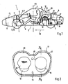
- Motor vehicle 1 cut open parallel to the vehicle longitudinal axis FL in particular a passenger car, has a body 3 supported by wheels 2 with a body 4 resting on a floor assembly 5 of the body 3 and comprising a plurality of walls 4 ', which walls 4' comprise a plurality of vehicle spaces 6, Limit 7, 8 and 9.
- an engine 10 of the motor vehicle 1 is accommodated, which is designed in particular as an internal combustion engine.
- the drive machine 10 is arranged in so-called. Mid-engine arrangement in the motor vehicle 1 in the vehicle compartment 8 and the vehicle compartments 6 and 9 form a rear and front luggage compartment.
- the prime mover 10 in the front vehicle compartment 6 or in the rear vehicle compartment 9, ie as a front or rear engine.
- the individual vehicle spaces 6, 7, 8 and 9 are surrounded by the walls 4 ', some of which are provided as partitions 11, 12 and 13 and each share two vehicle compartments 6, 7, 8, 9 from each other, wherein in front of an end wall or Bulkhead 11 ', the partition 11 is disposed and with this between the vehicle compartments 6 and 7 is located.
- the bulkhead 11 ' may form another partition.
- the partitions 11 ', 11, 12 and 13 are substantially upright or have at least one wall portion 14, which is substantially upright, that extends approximately in the direction of the vehicle vertical axis FH.
- a gear unit 15 flanged which in the embodiment shown - in the direction of travel FR - behind the drive machine 10 and in the embodiment shown below the bottom 9 'of the vehicle compartment 9 is arranged.
- the engine 10 is cooled with liquid and therefore comprises a cooling circuit not shown here in detail, from which in the Fig. 2 and 3 only one filling nozzle 16 is shown.
- the filling nozzle 16 is here associated with a service unit 17 which is arranged in one of the vehicle compartments 6, 8 or 9 on one of the walls 4 ', in particular one of the partitions 11, 12 or 13. In the exemplary embodiment, this is the partition wall 13 of the vehicle compartments 8 and 9.
- the service unit 17 comprises, in addition to the filling nozzle 16, an oil filler neck 18 which is closed by a lid 19.
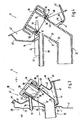
- the filling nozzle 16 comprises a filling opening 20, which is located in the vehicle compartment 9 and which is formed at a free end of a filling section 21 of the filling nozzle 16, which filling section 21 merges into an angled thereto connecting section 22, which is connected to the cooling circuit of the engine 10, not shown here connected. From the filling nozzle 16 with its tube wall 23, an overflow nozzle 24 goes out, which is close to the filling opening 20 and the filling section 21.
- the overflow pipe 24 is formed by a tubular extension which extends laterally from the filling nozzle 16 and has an inlet opening 25 in the pipe wall 23. It runs approximately parallel to the connection section 22 of the filling nozzle 16.
- the inlet opening 25 opposite the other end of the overflow nozzle 24 opens into the adjacent vehicle compartment 9 to the vehicle compartment 8, so that the filling opening 20 with respect to the partition wall 13 on a first side 26 and one of Inlet opening 25 opposite, end-side drain opening 27 of the overflow nozzle 24 comes to lie on the first side 26 opposite the second side 28 of the partition 13.
- the filling opening 20 is located in a different vehicle compartment 6, 7, 8, 9 than the drain opening 27 of the overflow nozzle 24. In the embodiment shown is thus on the first side 26 of the partition wall 13 of the vehicle compartment 9 and on the second side 28 of Partition wall 13 of the vehicle compartment 8.
- Fig. 1 between the vehicle outer skin 29 and the upright partition 13 is still a web plate 30 which divides the vehicle compartment 9 and the vehicle compartment 7, which could also be omitted, so that the designated also as a passenger compartment vehicle compartment 7 and to be used as a luggage compartment vehicle compartment. 9 form a continuous vehicle interior 31.
- FIG. 3 passes through the filling nozzle 16 with its connection portion 22, the partition wall 13 in an opening 32.
- a closure cap 34 for the filling nozzle 16 which sealingly closes the filling opening 20, for which purpose a seal 36 is mounted peripherally on an inner, for example tubular extension 35, which cooperates with the inner side 37 of the tube wall 23.
- the length LF of the extension 35 is dimensioned such that it forms a shut-off means for the overflow pipe 24 together with the seal 36, which extension 35 thus closes the spaced apart from the filling opening 20 overflow pipe 24 with its inlet opening 25 closes when the cap 34 on the Filling nozzle is completely attached.
- a corresponding securing means 38 can be provided, which is provided between the portion of the closure cap 34 that overlaps the filling nozzle 16 and the outside 39 of the tube wall 23.
- This securing means 38 can be designed in particular as a screw or bayonet closure.
- the extension 35 When the closure cap 34 is removed from the filling nozzle 16, the extension 35 thus releases the inlet opening 25 so that the hot liquid possibly under pressure in the cooling circuit enters the evacuation nozzle 24, directed away from the filling nozzle 16 to the second side 28 of the latter Guided partition 13 and can be derived there in the example below open engine compartment. It would be conceivable to attach an extension, for example in the form of a hose or the like, to the discharge opening 27 of the overflow connecting piece 24. As a result of the overflow connection 24, overpressure within the cooling circuit can thus be reduced when the closure cap 34 is removed, so that no cooling liquid emerges from the filling opening 20. Only after complete removal of the closure cap 34, when the overpressure is reduced, can the filling of the cooling circuit take place via the filling nozzle 16. In Fig. 3 is dash-dotted yet a connecting piece 40 indicated, which can enforce the partition 13 and is connected to a possibly existing expansion tank of the cooling circuit and the filling nozzle 16.
- the collecting tray 42 is recessed at a distance from the filling opening 20 in the direction of the connecting section 22, thereby concealing the overflow pipe 24 and, with its lower collar section 43, also protruding beyond the filling opening 20 located above it.
- drip tray 42 In order to be able to derive liquid collected in the drip tray 42, is - according to Fig. 3 - Provided in the region of the lower collar portion 43, a drain port 44 which is indicated by dash-dotted lines and in particular the partition wall 13 penetrates and so the liquid transported away in the space 8, so on the second side 28 opens into the room 8.
- drip tray 42 and outlet nozzle 44 are made in one piece.
- the filling nozzle 16, the overflow pipe 24 and the collecting tray 42 are integrally formed, for example as a plastic injection molded part.
- the connecting portion 22 and the filling portion 21 at an angle to each other and the overflow nozzle, which starts from the Einhellab4.000 21, extends approximately parallel to the connecting portion 22.
- the collecting tray 42 extends with its shell wall, so the collar 41, in the direction of the filling opening 20 so that the shell bottom 45 adjacent to the tube wall 23 of the filling nozzle 16 and the shell peripheral wall 46, starting from the shell bottom 45 extends substantially into the vehicle compartment 9 inside, whereby the drip tray 42 could possibly be made in one piece with the filling nozzle 16 and the overflow pipe 24. Possibly. the outlet connection 44 and the connection piece 40 can be realized in one piece with the filling connection 16.
- the drip tray 42 may be inserted into a cowling 47 that lines the divider wall 13 and the vehicle compartment 9, respectively, and that may be configured as a molded part and / or carpet trim.
- the filling nozzle is equipped with an extension 48, which is provided with a larger inner diameter of the tube 23 in relation to the remaining filling portion 21.
- the extension 48 has the filling opening 20 and carries the closure cap 34.
- the extension 48 is formed by a step 49 which widens the inner diameter of the tube 23 and which forms a stepped bottom 50 in the filling section 20, which serves as a sealing surface 51, the stepped bottom with which now cooperates at a fork-like front end 52 of the extension 35 of the closure cap 34 and thus forms the blocking means for the overflow pipe 24.
- an annular groove 53 is formed to receive the seal 36.
- Above the stepped bottom 50, ie adjacent to the filling opening 20, is the approximately inlet opening 25, which may be approximately oval in cross-section, when the overflow nozzle 24 attaches tangentially to the tube 23.
- the filling nozzle 16, overflow pipe 24 and possibly the connecting piece 40 may be made in one piece together with the collar 41.
- the collecting tray 42 is designed as a separate part and connected at a joint 54 with the collar 41, for example by gluing or welding. As related to Fig. 3 already explained, the drip tray 42 is inserted into the cowling 47 and at least the overflow nozzle 24 extends through the wall 4 '. Otherwise, in Fig. 4 the same or equivalent parts with the same reference numerals as in the Fig. 1 to 3 Mistake.
- the filling nozzle 16 are made with its outgoing nozzle 24, 40 and 44 and the collecting tray 42 made of plastic.
Landscapes
- Engineering & Computer Science (AREA)
- Chemical & Material Sciences (AREA)
- Combustion & Propulsion (AREA)
- Mechanical Engineering (AREA)
- General Engineering & Computer Science (AREA)
- Cooling, Air Intake And Gas Exhaust, And Fuel Tank Arrangements In Propulsion Units (AREA)
- Motor Or Generator Cooling System (AREA)
- Body Structure For Vehicles (AREA)
Claims (15)
- Véhicule automobile comprenant une carrosserie, une machine d'entraînement refroidie par un liquide par le biais d'un circuit de refroidissement et une tubulure de remplissage pour le circuit de refroidissement, laquelle tubulure de remplissage est dotée d'une ouverture de remplissage, d'un couvercle de fermeture amovible pour l'ouverture de remplissage et d'une tubulure de trop-plein comprenant une ouverture d'évacuation située du côté de son extrémité, lequel trop-plein est dégagé lorsque le couvercle de fermeture est retiré, caractérisé en ce que la tubulure de remplissage (16) traverse la paroi (4') de la carrosserie (4) et en ce que l'ouverture de remplissage (20) de la tubulure de remplissage (16) se situe d'un premier côté (26) de la paroi (4') de la carrosserie (4) et la tubulure de trop-plein (24) pourvue de son ouverture d'évacuation (27) débouche de l'autre côté de la paroi (6, 7, 8, 9), à savoir du deuxième côté (28) opposé au premier côté.
- Véhicule automobile selon la revendication 1, caractérisé en ce que la tubulure de trop-plein (24) part de la tubulure de remplissage (16) à proximité de l'ouverture de remplissage (20) et traverse la paroi (4') de la carrosserie (4).
- Véhicule automobile selon la revendication 1, caractérisé en ce que le couvercle de fermeture (34) comprend un prolongement intérieur (35) qui pénètre dans la tubulure de remplissage (16), lequel prolongement (35) forme un moyen de fermeture pour la tubulure de trop-plein (24) située à distance de l'ouverture de remplissage (20).
- Véhicule automobile selon la revendication 1, 2 ou 3, caractérisé en ce que la tubulure de trop-plein (24) part latéralement de la tubulure de remplissage (16) et comprend une ouverture de remplissage (25) dans la paroi tubulaire (23) de la tubulure de remplissage (16).
- Véhicule automobile selon la revendication 3, caractérisé en ce que le moyen de fermeture ferme l'ouverture de remplissage (25) lorsque le couvercle de fermeture (34) est placé sur la tubulure de remplissage (16) et libère l'ouverture de remplissage lorsque le couvercle de fermeture (34) est retiré.
- Véhicule automobile selon la revendication 1, caractérisé en ce que la tubulure de remplissage (16) est entourée, à proximité de l'ouverture de remplissage (20), au moins partiellement par un rebord (41) formant un bac collecteur (42).
- Véhicule automobile selon la revendication 6, caractérisé en ce que le bac collecteur (42) comprend une tubulure d'évacuation (44) qui débouche du deuxième côté (28) de la paroi (4') de la carrosserie (4).
- Véhicule automobile selon la revendication 6 ou 7, caractérisé en ce que la tubulure de remplissage (16) et le bac collecteur (42) sont réalisés d'un seul tenant.
- Véhicule automobile selon l'une quelconque des revendications précédentes, caractérisé en ce que la tubulure de remplissage (16), la tubulure de trop-plein (24) et le bac collecteur (42) sont réalisés d'un seul tenant, la tubulure de remplissage (16) comprenant une partie de raccordement (22) pour le circuit de refroidissement et une partie de remplissage (21) s'étendant suivant un angle par rapport à la partie de raccordement, laquelle partie de remplissage (21) comporte l'ouverture de remplissage (20), en ce que la tubulure de trop-plein (24) part de la partie de remplissage (21) et s'étend en l'occurrence approximativement parallèlement à la partie de raccordement (22) et en ce que le bac collecteur (42) part de la partie de remplissage (21) et s'étend de manière à ce que sa paroi périphérique de bac (46) soit orientée en direction de l'ouverture de remplissage (20).
- Véhicule automobile selon l'une quelconque des revendications 1 à 7, caractérisé en ce que la tubulure de remplissage (16) et le bac collecteur (42) sont réalisés respectivement sous forme de pièce séparée et sont reliés l'un à l'autre.
- Véhicule automobile selon la revendication 1, caractérisé en ce que la paroi (4') forme une paroi de séparation (11', 11, 12, 13) qui sépare un compartiment de moteur (compartiment de véhicule 8) pour la machine d'entraînement (10) et un autre compartiment de véhicule (6, 7, 9).
- Véhicule automobile selon les revendications 1 et 11, caractérisé en ce que la machine d'entraînement (10) est logée dans le véhicule automobile (1) suivant un agencement à moteur central et en ce que la paroi de séparation (11', 11, 12, 13) sépare le compartiment de moteur (compartiment de véhicule 8) d'un compartiment à bagages (compartiment de véhicule 9).
- Véhicule automobile selon l'une quelconque des revendications 11 et 12, caractérisé en ce que la paroi de séparation (11', 11, 12, 13) se dresse approximativement verticalement à l'intérieur de la carrosserie (4).
- Véhicule automobile selon les revendications 1 et 11, caractérisé en ce que le compartiment de moteur pour la machine d'entraînement (10) se situe du deuxième côté (28) de la paroi (4') et le compartiment à bagages se situe du premier côté (26) de la paroi (4').
- Véhicule automobile selon la revendication 11, 12, 13 ou 14, caractérisé en ce qu'un compartiment pour passagers (compartiment de véhicule 7) et le compartiment à bagages (compartiment de véhicule 9) forment un compartiment intérieur de véhicule (31).
Applications Claiming Priority (2)
| Application Number | Priority Date | Filing Date | Title |
|---|---|---|---|
| DE10359767 | 2003-12-19 | ||
| DE10359767A DE10359767B4 (de) | 2003-12-19 | 2003-12-19 | Kraftfahrzeug |
Publications (3)
| Publication Number | Publication Date |
|---|---|
| EP1548247A2 EP1548247A2 (fr) | 2005-06-29 |
| EP1548247A3 EP1548247A3 (fr) | 2012-02-01 |
| EP1548247B1 true EP1548247B1 (fr) | 2014-03-26 |
Family
ID=34530337
Family Applications (1)
| Application Number | Title | Priority Date | Filing Date |
|---|---|---|---|
| EP04022585.6A Expired - Lifetime EP1548247B1 (fr) | 2003-12-19 | 2004-09-22 | Véhicule |
Country Status (4)
| Country | Link |
|---|---|
| US (1) | US7172089B2 (fr) |
| EP (1) | EP1548247B1 (fr) |
| JP (1) | JP4063819B2 (fr) |
| DE (1) | DE10359767B4 (fr) |
Families Citing this family (7)
| Publication number | Priority date | Publication date | Assignee | Title |
|---|---|---|---|---|
| JP4455924B2 (ja) * | 2004-04-21 | 2010-04-21 | 株式会社パイオラックス | 管継手 |
| DE102004058327A1 (de) | 2004-12-03 | 2006-06-08 | Dr.Ing.H.C. F. Porsche Ag | Befüllstutzen für einen Kühlkreis einer Antriebsmaschine und Kraftfahrzeug mit einem derartigen Befüllstutzen |
| DE102005021456B4 (de) | 2005-05-10 | 2007-02-08 | Dr.Ing.H.C. F. Porsche Ag | Serviceeinheit zur Betriebsmittelergänzung |
| DE102005021457B4 (de) | 2005-05-10 | 2007-02-08 | Dr.Ing.H.C. F. Porsche Ag | Serviceeinheit zur Betriebsmittelergänzung |
| DE102007051022A1 (de) * | 2007-10-25 | 2009-04-30 | Bayerische Motoren Werke Aktiengesellschaft | Befüllanschluss für eine Fahrzeug-Klimaanlage |
| FR2964148A1 (fr) * | 2010-08-30 | 2012-03-02 | Peugeot Citroen Automobiles Sa | Boite de degazage destinee au circuit de refroidissement d'un moteur thermique de vehicule automobile |
| CN117645065A (zh) * | 2022-09-02 | 2024-03-05 | 本纳曼恩服务有限公司 | 真空密封装置和方法 |
Family Cites Families (21)
| Publication number | Priority date | Publication date | Assignee | Title |
|---|---|---|---|---|
| US1685918A (en) * | 1924-05-31 | 1928-10-02 | Karmazin John | Condenser |
| US3071285A (en) * | 1959-10-07 | 1963-01-01 | Stant Mfg Company Inc | Depressed pressure cap |
| US3062400A (en) * | 1960-05-03 | 1962-11-06 | Reuben J Humbert | Safety valved pressure caps |
| JPS5029517U (fr) * | 1973-07-13 | 1975-04-03 | ||
| US3910451A (en) * | 1973-10-01 | 1975-10-07 | Arthur P Tusing | Radiator cap |
| SE417123B (sv) * | 1974-06-27 | 1981-02-23 | Walter C Avrea | Anordning vid ett lock for tillslutning av en kylares pafyllningshals |
| US4185751A (en) * | 1978-07-31 | 1980-01-29 | Stant Manufacturing Company, Inc. | Radiator cap |
| JPS6033125A (ja) | 1983-08-02 | 1985-02-20 | Nissan Motor Co Ltd | リザ−バタンク |
| DE8901826U1 (de) * | 1988-11-23 | 1989-04-06 | Reutter Metallwarenfabrik GmbH, 71336 Waiblingen | Kühlerstutzen mit Verschlußdeckel |
| GB2240096A (en) * | 1990-01-20 | 1991-07-24 | Ford Motor Co | End fitting for a fuel filler pipe |
| US5248052A (en) * | 1992-07-31 | 1993-09-28 | Mellinger Larry L | Apparatus for automatically releasing the super-atmospheric pressure of an engine cooling system in response to turning off the engine and preventing the buildup of pressure while the engine is off |
| EP0760789B1 (fr) * | 1994-06-01 | 1998-08-26 | REUTTER, Heinrich | Ensemble bouchon fixable sur le col d'un reservoir |
| US5522456A (en) * | 1994-06-22 | 1996-06-04 | Geiger Technic, Inc. | Overflow with threaded plastic fillneck for surge tanks and overflow reservoirs |
| US5603425A (en) * | 1995-03-17 | 1997-02-18 | Western Thomson Controls Limited | Radiator cap |
| SE511623C2 (sv) * | 1997-02-12 | 1999-11-01 | Saab Automobile | Anordning vid bränslesystem i ett fordon |
| DE19718594B4 (de) * | 1997-05-02 | 2007-03-22 | Audi Ag | Personenkraftfahrzeug mit einer Motorhaube |
| DE19753597A1 (de) * | 1997-12-03 | 1999-06-24 | Heinrich Reutter | Verschlußdeckel für Kraftfahrzeugkühler |
| US6276312B1 (en) * | 1998-11-06 | 2001-08-21 | Stant Manufacturing Inc. | Thermal control cooling system vacuum valve |
| JP2000283692A (ja) * | 1999-03-30 | 2000-10-13 | Denso Corp | ネックフィラ及び注水構造 |
| DE19923775A1 (de) * | 1999-05-22 | 2000-11-23 | Heinrich Reutter | Verschlußdeckel für Kraftfahrzeugkühler |
| JP4106820B2 (ja) * | 1999-07-14 | 2008-06-25 | 株式会社デンソー | 完全密閉型容器 |
-
2003
- 2003-12-19 DE DE10359767A patent/DE10359767B4/de not_active Expired - Fee Related
-
2004
- 2004-09-22 EP EP04022585.6A patent/EP1548247B1/fr not_active Expired - Lifetime
- 2004-12-16 US US11/012,241 patent/US7172089B2/en not_active Expired - Lifetime
- 2004-12-16 JP JP2004364958A patent/JP4063819B2/ja not_active Expired - Fee Related
Also Published As
| Publication number | Publication date |
|---|---|
| DE10359767B4 (de) | 2006-01-19 |
| JP4063819B2 (ja) | 2008-03-19 |
| EP1548247A3 (fr) | 2012-02-01 |
| JP2005180445A (ja) | 2005-07-07 |
| US20050133112A1 (en) | 2005-06-23 |
| US7172089B2 (en) | 2007-02-06 |
| DE10359767A1 (de) | 2005-07-14 |
| EP1548247A2 (fr) | 2005-06-29 |
Similar Documents
| Publication | Publication Date | Title |
|---|---|---|
| EP1162100B1 (fr) | Dispositif d'alimentation en carburant | |
| DE69608764T2 (de) | Einfüllstutzen für einen Kraftstofftank | |
| EP2221097B1 (fr) | Dispositif de filtre destiné à l'adsorption d'hydrocarbures | |
| EP2093133B1 (fr) | Cabine de conducteur d'un véhicule utilitaire | |
| DE102010005236A1 (de) | Personenkraftfahrzeug mit innerhalb eines Fahrgastraumes angeordnetem Kraftstoffmodul | |
| EP1548247B1 (fr) | Véhicule | |
| EP1441935B1 (fr) | Reservoir d'eau pour essuie-glace | |
| WO2015067631A1 (fr) | Module de volet | |
| DE102015121515A1 (de) | Einlassstruktur für ein Fahrzeug mit Sattel | |
| EP3055156B1 (fr) | Tubulure de remplissage pour un contenant de fluide de fonctionnement d'un véhicule à moteur | |
| DE4023094C2 (de) | Kunststoff-Kraftstoffbehälter für ein Kraftfahrzeug | |
| DE102013201314B3 (de) | Außenspiegel für ein Kraftfahrzeug sowie Kraftfahrzeug | |
| DE3204493A1 (de) | Vorrichtung zur bildung eines wasserkastens und eines ausdehnungsgefaesses fuer einen waermeaustauscher | |
| DE3013990C2 (fr) | ||
| DE102009055138B4 (de) | Ölwanne mit einem nach oben versetzten Bodenabschnitt | |
| DE102009013508A1 (de) | Entwässerungsanordnung | |
| DE19612593A1 (de) | Umlaufhydrauliksystem | |
| EP2607133B1 (fr) | Agencement de tuyau de remplissage pour un récipient de réservoir de liquide pour véhicules automobiles | |
| EP0997633B1 (fr) | Système d'alimentation en carburant | |
| EP2426277B1 (fr) | Section de véhicule avant ou arrière | |
| DE19725336A1 (de) | Anlage zur Kühlung der Batterie eines mit einer Brennkraftmaschine versehenen Kraftfahrzeugs | |
| EP1666706B1 (fr) | Tubulure de remplissage de réservoir d'un circuit de refroidissement pour un moteur et véhicule automobile équipé d'une telle tubulure de remplissage de réservoir | |
| DE19948226A1 (de) | Kühlsystem mit wenigstens einem Ausgleichsbehälter | |
| DE2840813B1 (de) | Kuehler mit vertikalen Kuehlrohren und einer Entlueftungseinrichtung | |
| DE10151385A1 (de) | Modulare Vorrichtung zur Reinigung der Windschutzscheibe eines Kraftfahrzeuges |
Legal Events
| Date | Code | Title | Description |
|---|---|---|---|
| PUAI | Public reference made under article 153(3) epc to a published international application that has entered the european phase |
Free format text: ORIGINAL CODE: 0009012 |
|
| AK | Designated contracting states |
Kind code of ref document: A2 Designated state(s): AT BE BG CH CY CZ DE DK EE ES FI FR GB GR HU IE IT LI LU MC NL PL PT RO SE SI SK TR |
|
| AX | Request for extension of the european patent |
Extension state: AL HR LT LV MK |
|
| RAP1 | Party data changed (applicant data changed or rights of an application transferred) |
Owner name: DR. ING. H.C. F. PORSCHE AKTIENGESELLSCHAFT |
|
| RAP1 | Party data changed (applicant data changed or rights of an application transferred) |
Owner name: DR. ING. H.C. F. PORSCHE AKTIENGESELLSCHAFT |
|
| RAP1 | Party data changed (applicant data changed or rights of an application transferred) |
Owner name: DR. ING. H.C. F. PORSCHE AG |
|
| PUAL | Search report despatched |
Free format text: ORIGINAL CODE: 0009013 |
|
| AK | Designated contracting states |
Kind code of ref document: A3 Designated state(s): AT BE BG CH CY CZ DE DK EE ES FI FR GB GR HU IE IT LI LU MC NL PL PT RO SE SI SK TR |
|
| AX | Request for extension of the european patent |
Extension state: AL HR LT LV MK |
|
| RIC1 | Information provided on ipc code assigned before grant |
Ipc: F01P 11/02 20060101AFI20111227BHEP |
|
| 17P | Request for examination filed |
Effective date: 20120801 |
|
| AKX | Designation fees paid |
Designated state(s): DE FR GB IT SE |
|
| 17Q | First examination report despatched |
Effective date: 20120918 |
|
| GRAP | Despatch of communication of intention to grant a patent |
Free format text: ORIGINAL CODE: EPIDOSNIGR1 |
|
| INTG | Intention to grant announced |
Effective date: 20130326 |
|
| GRAP | Despatch of communication of intention to grant a patent |
Free format text: ORIGINAL CODE: EPIDOSNIGR1 |
|
| INTG | Intention to grant announced |
Effective date: 20130906 |
|
| GRAS | Grant fee paid |
Free format text: ORIGINAL CODE: EPIDOSNIGR3 |
|
| GRAA | (expected) grant |
Free format text: ORIGINAL CODE: 0009210 |
|
| AK | Designated contracting states |
Kind code of ref document: B1 Designated state(s): DE FR GB IT SE |
|
| REG | Reference to a national code |
Ref country code: GB Ref legal event code: FG4D Free format text: NOT ENGLISH |
|
| REG | Reference to a national code |
Ref country code: DE Ref legal event code: R096 Ref document number: 502004014564 Country of ref document: DE Effective date: 20140430 |
|
| PG25 | Lapsed in a contracting state [announced via postgrant information from national office to epo] |
Ref country code: SE Free format text: LAPSE BECAUSE OF FAILURE TO SUBMIT A TRANSLATION OF THE DESCRIPTION OR TO PAY THE FEE WITHIN THE PRESCRIBED TIME-LIMIT Effective date: 20140326 |
|
| REG | Reference to a national code |
Ref country code: DE Ref legal event code: R097 Ref document number: 502004014564 Country of ref document: DE |
|
| PLBE | No opposition filed within time limit |
Free format text: ORIGINAL CODE: 0009261 |
|
| STAA | Information on the status of an ep patent application or granted ep patent |
Free format text: STATUS: NO OPPOSITION FILED WITHIN TIME LIMIT |
|
| 26N | No opposition filed |
Effective date: 20150106 |
|
| PG25 | Lapsed in a contracting state [announced via postgrant information from national office to epo] |
Ref country code: IT Free format text: LAPSE BECAUSE OF FAILURE TO SUBMIT A TRANSLATION OF THE DESCRIPTION OR TO PAY THE FEE WITHIN THE PRESCRIBED TIME-LIMIT Effective date: 20140326 |
|
| REG | Reference to a national code |
Ref country code: DE Ref legal event code: R097 Ref document number: 502004014564 Country of ref document: DE Effective date: 20150106 |
|
| REG | Reference to a national code |
Ref country code: FR Ref legal event code: PLFP Year of fee payment: 13 |
|
| REG | Reference to a national code |
Ref country code: FR Ref legal event code: PLFP Year of fee payment: 14 |
|
| REG | Reference to a national code |
Ref country code: FR Ref legal event code: PLFP Year of fee payment: 15 |
|
| PGFP | Annual fee paid to national office [announced via postgrant information from national office to epo] |
Ref country code: FR Payment date: 20190926 Year of fee payment: 16 |
|
| PGFP | Annual fee paid to national office [announced via postgrant information from national office to epo] |
Ref country code: GB Payment date: 20190920 Year of fee payment: 16 |
|
| GBPC | Gb: european patent ceased through non-payment of renewal fee |
Effective date: 20200922 |
|
| PG25 | Lapsed in a contracting state [announced via postgrant information from national office to epo] |
Ref country code: FR Free format text: LAPSE BECAUSE OF NON-PAYMENT OF DUE FEES Effective date: 20200930 |
|
| PG25 | Lapsed in a contracting state [announced via postgrant information from national office to epo] |
Ref country code: GB Free format text: LAPSE BECAUSE OF NON-PAYMENT OF DUE FEES Effective date: 20200922 |
|
| P01 | Opt-out of the competence of the unified patent court (upc) registered |
Effective date: 20230526 |
|
| PGFP | Annual fee paid to national office [announced via postgrant information from national office to epo] |
Ref country code: DE Payment date: 20230728 Year of fee payment: 20 |
|
| REG | Reference to a national code |
Ref country code: DE Ref legal event code: R071 Ref document number: 502004014564 Country of ref document: DE |