EP1548270A1 - Connecteur avec une vanne encastrée - Google Patents
Connecteur avec une vanne encastrée Download PDFInfo
- Publication number
- EP1548270A1 EP1548270A1 EP20040106164 EP04106164A EP1548270A1 EP 1548270 A1 EP1548270 A1 EP 1548270A1 EP 20040106164 EP20040106164 EP 20040106164 EP 04106164 A EP04106164 A EP 04106164A EP 1548270 A1 EP1548270 A1 EP 1548270A1
- Authority
- EP
- European Patent Office
- Prior art keywords
- connector
- valve
- component
- upstream
- downstream
- Prior art date
- Legal status (The legal status is an assumption and is not a legal conclusion. Google has not performed a legal analysis and makes no representation as to the accuracy of the status listed.)
- Withdrawn
Links
Images


Classifications
-
- F—MECHANICAL ENGINEERING; LIGHTING; HEATING; WEAPONS; BLASTING
- F16—ENGINEERING ELEMENTS AND UNITS; GENERAL MEASURES FOR PRODUCING AND MAINTAINING EFFECTIVE FUNCTIONING OF MACHINES OR INSTALLATIONS; THERMAL INSULATION IN GENERAL
- F16K—VALVES; TAPS; COCKS; ACTUATING-FLOATS; DEVICES FOR VENTING OR AERATING
- F16K17/00—Safety valves; Equalising valves, e.g. pressure relief valves
- F16K17/02—Safety valves; Equalising valves, e.g. pressure relief valves opening on surplus pressure on one side; closing on insufficient pressure on one side
- F16K17/04—Safety valves; Equalising valves, e.g. pressure relief valves opening on surplus pressure on one side; closing on insufficient pressure on one side spring-loaded
-
- F—MECHANICAL ENGINEERING; LIGHTING; HEATING; WEAPONS; BLASTING
- F02—COMBUSTION ENGINES; HOT-GAS OR COMBUSTION-PRODUCT ENGINE PLANTS
- F02M—SUPPLYING COMBUSTION ENGINES IN GENERAL WITH COMBUSTIBLE MIXTURES OR CONSTITUENTS THEREOF
- F02M25/00—Engine-pertinent apparatus for adding non-fuel substances or small quantities of secondary fuel to combustion-air, main fuel or fuel-air mixture
- F02M25/08—Engine-pertinent apparatus for adding non-fuel substances or small quantities of secondary fuel to combustion-air, main fuel or fuel-air mixture adding fuel vapours drawn from engine fuel reservoir
- F02M25/0872—Details of the fuel vapour pipes or conduits
-
- Y—GENERAL TAGGING OF NEW TECHNOLOGICAL DEVELOPMENTS; GENERAL TAGGING OF CROSS-SECTIONAL TECHNOLOGIES SPANNING OVER SEVERAL SECTIONS OF THE IPC; TECHNICAL SUBJECTS COVERED BY FORMER USPC CROSS-REFERENCE ART COLLECTIONS [XRACs] AND DIGESTS
- Y10—TECHNICAL SUBJECTS COVERED BY FORMER USPC
- Y10T—TECHNICAL SUBJECTS COVERED BY FORMER US CLASSIFICATION
- Y10T137/00—Fluid handling
- Y10T137/7722—Line condition change responsive valves
- Y10T137/7837—Direct response valves [i.e., check valve type]
- Y10T137/7854—In couplings for coaxial conduits, e.g., drill pipe check valves
Definitions
- the present invention relates to a connector having a valve embedded therein for use in evaporation piping of fluid through the connector, for example, in the fuel supply system of an automobile.
- a popular vapor discharge prevention mechanism that provides such a treatment is the type in which the generated vapor is adsorbed in a canister.
- the vapor discharge prevention mechanism of this type requires evaporation piping for connecting a fuel tank with a canister or breather circuit, or for connecting a fuel tank with inlet piping, for which a reduction in the amount of vapor generated during the fuel supply is essential and the canister size must be reduced.
- a one-way valve or a check valve is used to serve the above purposes by maintaining the appropriate pressure inside the fuel tank.
- Such a one-way valve used for evaporation piping or breather piping for example is embedded in the connector housing of a piping connector as taught in U.S. Patent 6,397,884 and Japanese Unexamined Patent Application Publication No.2003-028010.
- the embedded valve comprises: a valve seat provided to the path or through-path of the connector housing; a valve body for opening or closing the valve gate and restricting the flow rate of the vapor flowing from the fuel tank to the canister or inlet-pipe side; and, a compression coil spring which pushes the valve body toward the fuel tank.
- the valve body moves to the canister side or inlet against the spring force of the compression coil spring, thereby opening the valve gate.
- the accumulated vapor in the fuel tank flows into the canister or inlet pipe through the embedded valve.
- the amount of vapor flowing from the fuel tank side to the canister side or to the inlet pipe side is mostly dependent on how much the valve gate that is seated on the valve body opens.
- the spring characteristics determine not only the minimum pressure applied to the valve body to open the valve gate, but also the vapor flow, rate from the fuel tank side to the canister or inlet-pipe side.
- the motions of a valve body can become unstable after the valve is open: for example, any change in the vapor pressure shakes the valve body. Unstable motions of the valve body cannot stabilize the vapor flow rate. Yet, minimizing the vapor flow rate is desirable in order to suppress evaporation so as to maintain a low vapor level thereof.
- the objective of the present invention is, therefore, to provide a connector with a long-life embedded valve that can ensure a stable flow rate.
- the connector of the present invention comprises: a connector housing having a path for fluid flow through the connector, an embedded valve embedded in the fluid path of the connector housing , a first connector component provided upstream of the embedded valve for upstream piping and a second connector component provided downstream of the embedded valve for downstream piping; wherein the embedded valve comprises: a valve seat provided in the fluid path of the connector housing having a valve gate; a valve body which opens or closes the valve gate on the valve seat; a compression coil spring which pushes the valve body in the upstream direction , and an exit-orifice disposed downstream of the valve seat for restricting the discharge rate of fluid flow through the downstream piping.
- the spring characteristics of the compression coil spring are; for example, set for the purpose of ensuring a given pressure required to open the valve.
- the cross-sectional area to diameter ratio at the exit-orifice or the cross-sectional area to diameter ratio of the fluid path at the exit orifice is set on the assumption that, for example, a given pressure results in a given flow rate from upstream to downstream.
- the characteristics of a valve embedded in the connector of the present invention are dependent on the exit- orifice and the characteristics of the compression coil spring. Hence, the valve body motion can be stabilized.
- valve body may slide along the inner circumference of the path being shaken in a radial direction. If the valve body slides along the inner circumference of the path, noise from abrasion occurs and is transmitted to the passenger compartment of an automobile, thereby disturbing the silence thereof. For this reason, it is desirable that an inlet-end orifice is provided more toward upstream than the valve seat provided in the path of the connector housing so as to stabilize the fluid flow coming from the upstream piping.
- the connector and embedded valve of the present invention has excellent durability because of its ability or certain valve characteristics to withstand aging.
- the flow rate of the connector is not controlled only by the force derived from the compression coil spring, and motions of the valve body are stabilized to produce a minimal effect on the fluid flow rate. This effectively prevents the internal fluid from evaporation and provides a good degree of freedom in designing of the connector.
- the exit-end orifice and the compression coil spring together will determine the valve characteristics. Accordingly, the number of compression coil springs to be managed is reduced and the components to be assembled are easily obtained while reducing manufacturing costs thereof.
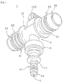
- Connector 1 having an embedded valve used for the evaporation piping of a gasoline fuel tank comprises for example: connector housing 3 made of polyacetal (POM); and check valve 7 embedded in path 5 of connector housing 3.
- Connector housing 3 further comprises: body component 9, having embedded check valve 7; first connector component 11; and second connector component 13 such that these three components are integrated to provide a T-shape wherein first connector component 11 with a smaller diameter is formed upstream and extends along the axis; second connector component 13 with a larger diameter is formed downstream and extends in the direction orthogonal to the axial direction.
- first connector component 11 is constructed with: upstream component 15 and downstream component 21; wherein upstream component 15 has an outer circumferential plane with a diameter gradually expanding in the downstream direction; two protruding flange components 19, 19 with a triangle shape in cross-section having a diameter expanding in the downstream direction are provided at a distance along the axis one after another from upstream to downstream.
- a resin tube for upstream piping (hereinafter referred to as first resin tube 23), as shown in Figure 5, is tightly fitted to the outer circumference or outer circumferential plane to connect the resin tube thereto.
- Upstream outer circumferential plane 25 of downstream component 21 between upstream component 15 and protruding flange component 17 is formed with a small diameter or is formed as a relatively deep groove. Seal-ring or first seal-ring 27, shown in Figure 5, is placed on upstream outer circumferential plane 25 to fit the resin tube thereto.
- the inner circumferential plane of first connector component 11 is a cylindrical inner surface throughout the length and inlet 29 or a part of path 5 is provided thereon. It also constitutes inlet orifice 31 having, for example, half of the diameter of inlet 29 at the upstream edge or tip portion.
- Upstream body component 9 of connector housing 3 has valve housing component 33 formed integrally with cylindrical first connector component 11 having a small diameter; downstream body component 9 has outlet component 35 formed integrally with cylindrical second connector component 13 having a large diameter; valve housing 33 and outlet component 35 are integrated by tightening the upstream portion of outlet component 35 about the outer circumference of the downstream portion of valve housing component 33 during ultrasound welding.
- Reference Numeral 36 is such a welded portion.
- Outlet component 35 is constructed with cylindrical base 37 and fitting component 39 having a large diameter wherein cylindrical base 37 is a downstream short extension along the axis which is incorporated with the center length of second connector component 13; fitting component 39 is incorporated with the upstream portion of cylindrical base 37 such that fitting component 39 is fitted to the outer circumference of the downstream portion of valve housing component 33.
- Annular spring-receiving groove 41 is provided to the annular plane of upstream cylindrical base 37.
- the inner plane of cylindrical base 37 is a simple cylinder and constitutes outlet 43.
- Outlet 43 and the inside second connector component 13 communicate with each other through exit-end orifice 45.
- Exit-end orifice 45 is given about 1 ⁇ 4 of the inner diameter of outlet 43 on cylindrical base 37.
- Upstream inner plane 47 of valve housing component 33 of connector housing 3 is a simple cylindrical plane extending with a diameter which is 1.5 times larger than that of outlet 29 of first connector component 11, and provides guiding hole 49 which is a part of path 5 having a nearly equal diameter to that of outlet 43 of cylindrical base 37; downstream inner plane 47 is a simple cylindrical plane extending with a diameter which is 1.7 times longer than that of guiding hole 49, and provides sliding hole 51 which is a part of path 5 as well.
- inner plane 47 of valve housing 33 has first taper component 53 and second taper component 55, wherein first taper component 53 extends from one axial end of slide hole 51 toward upstream inner plane 47 in such a manner that the diameter of valve housing component 33 reduces relatively sharply in a tapered manner; second taper component 55 extends from the upstream of first tapered component 53 to the other axial end of the guiding hole in such a manner that the diameter of housing component 33 reduces relatively gradually in a tapered manner.
- Second tapered component 55 or the inner plane thereof functions as a valve seat, providing a valve gate inside the valve seat.
- Valve body 57 constituting embedded check valve 7 is housed in valve housing component 33.
- valve body 57 is integrally formed with blockage component 63, downstream guide 65, and upstream guide 67 wherein blockage component 63 is formed integrally about the outer circumference of thin disk-like component 59 with annular component 61 slightly extending in the downstream direction; upstream guide 67 extends from the outer circumference of disk-like component 59 of blockage component 63 in the upstream direction.
- the material used for valve body 57 is POM.
- Figure 4 is a perspective view of valve body 57.
- connecting outer circumferential plane 69 for disk-like component 59 and annular component 61 is formed in such a manner that connecting outer circumferential plane 69 circularly expands outward in cross-section, thereby providing a contact plane which closely touches second tapered component 55 or a valve seat having a liner cross-section [(See Figure 6)].
- Downstream guide 65 is constructed with multiple, specifically six, plate-like downstream sliding legs 71 that are formed integrally with annular component 61 about the circumference thereof at an even distance, more specifically, at a 60 degree angle.
- Each downstream sliding leg 71 comprises: holding component 73 provided on annular component 61; and rectangular sliding component 75 formed integrally with the other end of holding component 73 along the axis in such a manner that the thickness direction of these plates corresponds to the tangent direction of annular component 61.
- the distance from the center of annular component 61 to the outer end plane along the radius of each sliding component 75 is equal to or somewhat smaller than the radius of the inner circumferential plane of sliding hole 51; the outer end plane along the radius of each sliding component 75 is formed as a plane extending along the axis of sliding component 75 such that the downstream connector 13 can slide along the inner circumferential plane of sliding hole 51.
- Holding grooves 77 extending or having slits pointing in the upstream direction are formed to be at nearly identical positions along the radius of annular component 61.
- Upstream sliding guide 67 is constructed with multiple, specifically four, plate-like sliding legs 79 formed integrally with the outer circumference of disk-like component 59 at even intervals, specifically at 90 degree angles, about the circumference thereof.
- Upstream sliding legs 79 are arranged to form right angles with the thickness direction of the plates, which corresponds to the tangential direction of disk-like component 59, and with the radial-outer end of the plates extending along the axis.
- the distance between the central part of disk-like component 59 and the outer end or outer end plane along the radius of upstream sliding leg 79 is approximately equal to or slightly smaller than the radius of the inner circumferential plane of guiding hole 49.
- the outer end plane along the radius of upstream sliding leg 79 is formed such that it can slide along the inner circumferential plane of guiding hole 49.
- valve body 57 of the above configuration is housed in holding groove 77 formed on sliding component 75 of downstream sliding leg 71. It is also pushed by compression coil spring 81 in the upstream direction to cause upstream guide 67 to enter guiding hole 49 of body component 9 and to cause connecting outer circumferential plane 69 of blockage component 63 to touch approximately the mid point along the axis of second tapered component 55 or the valve seat, wherein the downstream portion of compression coil spring 81 is housed in spring receiving groove 41 on cylindrical base 37.
- second connector component 13 has connector components 83, 83 of the same configuration at the first and second end along the length direction or the direction perpendicular to the axis.
- Each connector component 83 comprises: length-wise outer side component 85 and length-wise center side component 91 wherein outer side component 85 has an outer circumferential plane whose diameter increases toward the center along the length thereof; center side component 91 has protruding flange component 87 in a rectangular shape in cross-section and two protruding flange components 89, 89 in a triangular shape in cross-section; all of 87, 89, and 89 are formed about the outer circumferential plane, which is a simple cylindrical outer plane extending at the center side of length-wise outer side component 85; the diameter of the outer circumferential plane thereof increases towards the center along the length; and two protruding flange components 89, 89 are formed one after another from the outside to the center side at a distance along the length.
- the resin tubes of the downstream piping consists of second resin tube 93 and third resin tube 95 (See Figure 5) and these are tightly fitted to the outer circumference or outer circumferential plane to provide a connection thereof.
- Length-wise outer circumferential plane 97 on center side component 91 between outer side component 85 along the length and protruding flange component 87 is formed as a relatively deep annular groove. Accordingly, the sealing rings or second sealing ring 99 and third sealing ring 105 (See Figure 5) are arranged along the length to fit the resin tube thereto.
- Reference Numeral 103 is a hook component.
- Figure 5 is a diagram illustrating connector 1 with an embedded valve used for evaporation piping.
- the evaporation piping is configured as follows: first resin tube 23, which extends from a gasoline fuel tank, is fitted to the outer circumference of first connector component 11 of connector 1 with an embedded valve. Second resin tube 93 (downstream piping) for use in upstream piping, which is different from first resin tube 23, is fitted to connector elements 83 of second connector component 13; and third resin tube 95 (downstream piping) for use in downstream piping, which is not the piping in which first resin tube 23 and second resin tube 93 are used, is fitted to other connector elements 83 of second connector component 13.
- Reference Numerals 105, 107, and 109 are flanges that regulate the amount of the resin tube to be fitted or pressed therein.
- valve body 57 moves in the downstream direction against a spring force generated by compression coil spring 81 to cause the valve body 57 to open (Figure 6 is a diagram illustrating valve body 57 in the open state).
- vapor flows into sliding hole 51 (arrow A) through the annular space with a large diameter between connecting outer circumferential plane 69 and the axial midpoint of second tapered component 55.
- the incoming vapor flows out from outlet 43 and enters second connector 13 (arrow B) through exit-end orifice 45.
- valve body 57 can move in the downstream direction until sliding component 75 of second end siding leg 71 touches the annular upstream end plane of cylindrical base 37.
- the motion of valve body 57 along the axis causes guiding hole 49 of upstream sliding leg 79 and sliding hole 51 of downstream sliding leg 71 on the inner circumferential planes thereof to slide together.
- valve body 57 will not tilt during the movement. If the vapor flow is disturbed, valve body 57 is pressed against inner circumferential plane 47 of body component 9 in a biased manner, possibly generating a fricative sound. Nevertheless, the presence of the inlet-end orifice at the edge of the upstream of first connector component 11 along the axis can stabilize the vapor flow.
- upstream sliding leg 79 will not be pushed away from guiding hole 49 because upstream sliding leg 79 is of a length longer than the distance between downstream sliding leg 71 and upstream cylindrical base 37 as is shown in Figure 3 or the movable distance that valve body 57 travels along the longitudinal axis (from the valve open to valve closed position) provided that the valve body 57 is blocked.
- Figure 7 is a chart illustrating the pressure-flow rate (PQ) characteristic as a function of diameter or cross-sectional area of exit-end orifice 45.
- the connector and embedded valve of the present invention is installed in the evaporation piping in an automobile, for example, the vapor generated in the fuel tank can be handled appropriately.
Landscapes
- Engineering & Computer Science (AREA)
- General Engineering & Computer Science (AREA)
- Mechanical Engineering (AREA)
- Chemical & Material Sciences (AREA)
- Combustion & Propulsion (AREA)
- Check Valves (AREA)
- Pipe Accessories (AREA)
Applications Claiming Priority (2)
| Application Number | Priority Date | Filing Date | Title |
|---|---|---|---|
| JP2003400424A JP4352879B2 (ja) | 2003-11-28 | 2003-11-28 | バルブ内蔵コネクタ |
| JP2003400424 | 2003-11-28 |
Publications (1)
| Publication Number | Publication Date |
|---|---|
| EP1548270A1 true EP1548270A1 (fr) | 2005-06-29 |
Family
ID=34544877
Family Applications (1)
| Application Number | Title | Priority Date | Filing Date |
|---|---|---|---|
| EP20040106164 Withdrawn EP1548270A1 (fr) | 2003-11-28 | 2004-11-29 | Connecteur avec une vanne encastrée |
Country Status (3)
| Country | Link |
|---|---|
| US (1) | US20050115615A1 (fr) |
| EP (1) | EP1548270A1 (fr) |
| JP (1) | JP4352879B2 (fr) |
Cited By (4)
| Publication number | Priority date | Publication date | Assignee | Title |
|---|---|---|---|---|
| WO2009051737A3 (fr) * | 2007-10-17 | 2009-06-25 | Kohler Co | Systèmes et procédés de régulation du débit de purge dans un moteur à combustion interne |
| EP2458173A1 (fr) * | 2010-11-29 | 2012-05-30 | Veritas Ag | Agencement de vannes |
| US8677978B2 (en) | 2010-03-03 | 2014-03-25 | Kohler Co. | System and method for carburetor venting |
| US10308109B2 (en) | 2015-03-16 | 2019-06-04 | Sumitomo Riko Company Limited | Resinous filler port |
Families Citing this family (9)
| Publication number | Priority date | Publication date | Assignee | Title |
|---|---|---|---|---|
| JP2010048360A (ja) | 2008-08-22 | 2010-03-04 | Sanoh Industrial Co Ltd | 管継手 |
| JP6141712B2 (ja) | 2013-07-22 | 2017-06-07 | 住友理工株式会社 | 燃料ライン用ジョイント |
| JP6321423B2 (ja) | 2014-03-26 | 2018-05-09 | 住友理工株式会社 | 配管固定具 |
| JP6384164B2 (ja) * | 2014-07-15 | 2018-09-05 | 浜名湖電装株式会社 | 燃料蒸発ガスパージシステムの異常検出装置 |
| CN106382427B (zh) * | 2016-11-21 | 2018-03-02 | 常州帝斯博医疗用品有限公司 | 一种防滴漏吸引管连接接头 |
| FR3062191B1 (fr) * | 2017-01-25 | 2020-11-13 | Saipem Sa | Soupape de pression differentielle pour conduite sous-marine de transport de fluides et piece de jonction a bride de limitation de propagation d'ecrasement comprenant une telle soupape |
| JP2021001634A (ja) * | 2019-06-20 | 2021-01-07 | 三桜工業株式会社 | 管継手、及び管継手セット |
| JP7651248B2 (ja) | 2021-01-20 | 2025-03-26 | 株式会社ダンレイ | 逆止弁 |
| JP7233117B2 (ja) * | 2021-01-22 | 2023-03-06 | 株式会社不二工機 | 逆止弁及び弁装置 |
Citations (6)
| Publication number | Priority date | Publication date | Assignee | Title |
|---|---|---|---|---|
| US2960998A (en) * | 1956-04-30 | 1960-11-22 | David H Sinker | Check valve |
| JPH06300150A (ja) * | 1993-02-18 | 1994-10-28 | Miyano:Kk | 弁付管継手、チェック弁およびチェック弁構造 |
| JP2000018406A (ja) * | 1998-06-29 | 2000-01-18 | Ckd Corp | 逆止弁 |
| EP0987505A2 (fr) * | 1998-09-18 | 2000-03-22 | TGK Co., Ltd. | Vanne d'expansion du type à commande du degré de surrefroidissement |
| US20020036015A1 (en) * | 2000-09-25 | 2002-03-28 | Tokai Rubber Industries, Ltd. | Connection structure and valved connection member |
| EP1199476A2 (fr) * | 2000-10-16 | 2002-04-24 | Kabushiki Kaisha Toyota Jidoshokki | Pompe à vide |
Family Cites Families (14)
| Publication number | Priority date | Publication date | Assignee | Title |
|---|---|---|---|---|
| US1214595A (en) * | 1912-03-30 | 1917-02-06 | Nathan B Sands | Relief-valve. |
| US1187300A (en) * | 1916-02-02 | 1916-06-13 | George W Girard | Pressure-indicator. |
| US1841029A (en) * | 1928-07-13 | 1932-01-12 | Alfred E Hamilton | Valve |
| US1972169A (en) * | 1929-07-05 | 1934-09-04 | Spencer Thermostat Co | Valve |
| US2538364A (en) * | 1945-07-02 | 1951-01-16 | Ralph W James | Valve |
| US2612841A (en) * | 1948-09-29 | 1952-10-07 | Louis G Simmons | Variable retraction discharge valve for fuel injection pumps |
| US2903014A (en) * | 1953-12-04 | 1959-09-08 | Richard H Sheppard | Check valve for diesel engine fuel pump |
| US2822817A (en) * | 1956-06-08 | 1958-02-11 | Scott Aviation Corp | Filler valve |
| US3025874A (en) * | 1960-04-25 | 1962-03-20 | Superior Valve And Fittings Co | Pressure relief valve |
| US4274431A (en) * | 1979-01-10 | 1981-06-23 | Keller Russell D | Fuel vent with gravity valve |
| US4413645A (en) * | 1980-12-24 | 1983-11-08 | National Machine Company, Inc. | Fluid swivel valve device |
| US4437491A (en) * | 1982-04-21 | 1984-03-20 | Brown David E | Valve piston |
| US6695228B2 (en) * | 2000-08-22 | 2004-02-24 | Chapin Manufacturing, Inc. | Self-pressurizing sprayer |
| JP3984524B2 (ja) * | 2002-09-27 | 2007-10-03 | 東海ゴム工業株式会社 | バルブ内蔵コネクタ |
-
2003
- 2003-11-28 JP JP2003400424A patent/JP4352879B2/ja not_active Expired - Fee Related
-
2004
- 2004-11-24 US US10/996,717 patent/US20050115615A1/en not_active Abandoned
- 2004-11-29 EP EP20040106164 patent/EP1548270A1/fr not_active Withdrawn
Patent Citations (6)
| Publication number | Priority date | Publication date | Assignee | Title |
|---|---|---|---|---|
| US2960998A (en) * | 1956-04-30 | 1960-11-22 | David H Sinker | Check valve |
| JPH06300150A (ja) * | 1993-02-18 | 1994-10-28 | Miyano:Kk | 弁付管継手、チェック弁およびチェック弁構造 |
| JP2000018406A (ja) * | 1998-06-29 | 2000-01-18 | Ckd Corp | 逆止弁 |
| EP0987505A2 (fr) * | 1998-09-18 | 2000-03-22 | TGK Co., Ltd. | Vanne d'expansion du type à commande du degré de surrefroidissement |
| US20020036015A1 (en) * | 2000-09-25 | 2002-03-28 | Tokai Rubber Industries, Ltd. | Connection structure and valved connection member |
| EP1199476A2 (fr) * | 2000-10-16 | 2002-04-24 | Kabushiki Kaisha Toyota Jidoshokki | Pompe à vide |
Non-Patent Citations (2)
| Title |
|---|
| PATENT ABSTRACTS OF JAPAN vol. 1995, no. 01 28 February 1995 (1995-02-28) * |
| PATENT ABSTRACTS OF JAPAN vol. 2000, no. 04 31 August 2000 (2000-08-31) * |
Cited By (5)
| Publication number | Priority date | Publication date | Assignee | Title |
|---|---|---|---|---|
| WO2009051737A3 (fr) * | 2007-10-17 | 2009-06-25 | Kohler Co | Systèmes et procédés de régulation du débit de purge dans un moteur à combustion interne |
| US8156924B2 (en) | 2007-10-17 | 2012-04-17 | Kohler Co. | Systems and methods for regulating purge flow rate in an internal combustion engine |
| US8677978B2 (en) | 2010-03-03 | 2014-03-25 | Kohler Co. | System and method for carburetor venting |
| EP2458173A1 (fr) * | 2010-11-29 | 2012-05-30 | Veritas Ag | Agencement de vannes |
| US10308109B2 (en) | 2015-03-16 | 2019-06-04 | Sumitomo Riko Company Limited | Resinous filler port |
Also Published As
| Publication number | Publication date |
|---|---|
| JP4352879B2 (ja) | 2009-10-28 |
| US20050115615A1 (en) | 2005-06-02 |
| JP2005163836A (ja) | 2005-06-23 |
Similar Documents
| Publication | Publication Date | Title |
|---|---|---|
| US20050115615A1 (en) | Connector having an embedded valve | |
| US20060037647A1 (en) | Check valve | |
| US3421547A (en) | Check valve mechanism | |
| US6397884B1 (en) | Connection structure and valved connection member | |
| JP5064104B2 (ja) | 圧力調節弁 | |
| US6877525B2 (en) | Check valve for fuel pump | |
| CN111720580B (zh) | 流体控制阀 | |
| US8322361B2 (en) | Methods, apparatus and/or systems relating to controlling flow through concentric passages | |
| US20040007271A1 (en) | Check valve | |
| US7287546B2 (en) | Simple structure of fuel pressure regulator designed to minimize pressure loss | |
| KR101214703B1 (ko) | 차량의 연료관에 사용하기 위한 밸브 | |
| US7686033B2 (en) | Valve connector | |
| US20030037822A1 (en) | Check valve for fuel pump | |
| JP7653231B2 (ja) | 電磁弁のための弁カートリッジ | |
| US6994108B2 (en) | Check valve for fuel pump | |
| US7552745B2 (en) | Valve connector | |
| JP2020020366A (ja) | 圧力制御弁 | |
| JP2005042919A (ja) | 圧力調節弁 | |
| US20230078885A1 (en) | Control valve | |
| JP2009180377A (ja) | バルブ内蔵コネクタ | |
| US20050263187A1 (en) | Check valve barbed casing | |
| US20210033208A1 (en) | Check valve | |
| JP2020128744A5 (fr) | ||
| WO2024195135A1 (fr) | Dispositif de soupape de limitation de débit et ensemble soupape | |
| US11353114B1 (en) | Control valve |
Legal Events
| Date | Code | Title | Description |
|---|---|---|---|
| PUAI | Public reference made under article 153(3) epc to a published international application that has entered the european phase |
Free format text: ORIGINAL CODE: 0009012 |
|
| AK | Designated contracting states |
Kind code of ref document: A1 Designated state(s): AT BE BG CH CY CZ DE DK EE ES FI FR GB GR HU IE IS IT LI LU MC NL PL PT RO SE SI SK TR |
|
| AX | Request for extension of the european patent |
Extension state: AL HR LT LV MK YU |
|
| 17P | Request for examination filed |
Effective date: 20051107 |
|
| AKX | Designation fees paid |
Designated state(s): FR |
|
| REG | Reference to a national code |
Ref country code: DE Ref legal event code: 8566 |
|
| 17Q | First examination report despatched |
Effective date: 20051229 |
|
| STAA | Information on the status of an ep patent application or granted ep patent |
Free format text: STATUS: THE APPLICATION IS DEEMED TO BE WITHDRAWN |
|
| 18D | Application deemed to be withdrawn |
Effective date: 20070118 |