EP1548294A2 - Support de tringle - Google Patents
Support de tringle Download PDFInfo
- Publication number
- EP1548294A2 EP1548294A2 EP04030430A EP04030430A EP1548294A2 EP 1548294 A2 EP1548294 A2 EP 1548294A2 EP 04030430 A EP04030430 A EP 04030430A EP 04030430 A EP04030430 A EP 04030430A EP 1548294 A2 EP1548294 A2 EP 1548294A2
- Authority
- EP
- European Patent Office
- Prior art keywords
- support according
- recess
- fixing means
- longitudinal axis
- opening
- Prior art date
- Legal status (The legal status is an assumption and is not a legal conclusion. Google has not performed a legal analysis and makes no representation as to the accuracy of the status listed.)
- Withdrawn
Links
Images





Classifications
-
- A—HUMAN NECESSITIES
- A47—FURNITURE; DOMESTIC ARTICLES OR APPLIANCES; COFFEE MILLS; SPICE MILLS; SUCTION CLEANERS IN GENERAL
- A47H—FURNISHINGS FOR WINDOWS OR DOORS
- A47H1/00—Curtain suspension devices
- A47H1/10—Means for mounting curtain rods or rails
- A47H1/14—Brackets for supporting rods or rails
Definitions
- the present invention relates to a rod support with multiple means of fixation.
- the field of the invention is that of living quarters in which find decorative materials that obscure the windows, such as curtains or curtains, and separating materials fencing shower trays or bathtubs, and opposing splashing water, such as shower curtains.
- These materials are present in the form of flexible panels of fabrics or plastics, arranged mobile way on rods, usually via hooks or rings.
- rods generally of circular or rectangular section, full or hollow, are positioned on a fixed structure, for example a wall or a partition, via rod supports. These are usually located near the ends of those, often at the ends.
- rod supports are commonly in the form of a metal or plastic body.
- This body is connected at one end to a plate perpendicular to the axis of the body and provided with screw holes, allowing its fixation on a support surface.
- This body has at its other end a recess of circular or rectangular section adapted to receive rods, the plane of this recess being perpendicular to the axis of the rod and to the plane of the surface support.
- the rod can be locked in this recess with a screw of blocking. This screw is supported in a screw hole on the periphery of the recess and in the plane of the latter.
- the locking screw is indispensable and complicates the support structure.
- it can damage the surface of a rod by stripe or punching, especially if the latter has a decorative role or if it has a hollow section.
- the invention proposes to overcome these various limitations by means of a advanced rod support.
- it also comprises a second fixing means adapted to a second type of rod different from the first type.
- the first fixing means comprises a first cylindrical recess opening on its end face, this recess presenting a first predetermined section and a first longitudinal axis parallel to its back side.
- the first means further comprises a first slot perpendicular to the first longitudinal axis and opening into the first recess.
- the second means comprises a second recess cylindrical opening on its front face, this recess having a second predetermined section different from the first section and a second axis longitudinal parallel to its rear face.
- the second means further comprises a perpendicular slot at the second longitudinal axis and opening into the second recess.
- the first means is able to receive section rods circular diameter between 6 and 8 millimeters
- the second means is able to receive rods with circular section of diameter between 9 and 12 millimeters.
- the first means comprises a third recess parallelepiped coplanar to its rear face and opening on its front face, this recess having a third predetermined section and a third axis longitudinal.
- the second means further comprises a third slot perpendicular to the third longitudinal axis, this slot crossing the third recess and opening on its front face.
- the second and third recesses are coaxial.
- it also comprises a third means of fixation.
- the third means comprises a fourth recess parallelepiped coplanar to its rear face and opening on its front face, this recess having a fourth predetermined section and a fourth longitudinal axis.
- the third means further comprises a fourth slot perpendicular to the fourth longitudinal axis, this slot crossing the fourth recess and opening on its front face.
- first and fourth recesses are coaxial.
- the support comprises a fourth fixing means.
- the fourth means comprises a fifth coplanar parallelepipedic recess at its rear face and opening onto its front face, this recess having a fifth predetermined section and a fifth longitudinal axis.
- the fourth means further comprises a fifth slot perpendicular to the fifth longitudinal axis, this slot crossing the fifth recess and opening on its front face.
- the support is adapted to a rod having a section rectangular of 12 by 8 millimeters.
- the second and fourth recesses are coaxial.
- the fixing means have axes coplanar with angular offset.
- the angular offset is 90 °.
- the fixing means are arranged in a body cylindrical.
- the cylindrical body is made of an elastic material, so that it allows the fixing of the rods by interlocking.
- the securing means consist of an adhesive.
- the securing means consist of an orifice, so that the support can be screwed on the structure.
- this support has an adjustable hood on the body and presenting openings adapted to the fastening means.
- the hood includes clipping means on the body cylindrical.
- the hood includes locking means for blocking a rod in translation.
- At least one of the support elements is presented under the shape of a pre-cut area.
- At least one of the fastening means present against rods, reliefs intended to immobilize a rod in rotation and in translation.
- Figure 1 shows a rod support.
- the latter consists of a PLA plate and COR body.
- the PLA plate delimited by two parallel planes corresponding to the face FAA back and the PLM middle face is usually discoidal. She can be secured by its FAA back side on a support surface locally coplanar to FAA by gluing or screwing. In the latter case, she is equipped a central screwing hole ORI, or several screw holes.
- the COR body is generally cylindrical, delimited by two sections coplanar lines with two parallel planes FAA, PLM.
- the PLM middle face is common to the COR body and the PLA plate, the COR body being affixed on the PLA plate.
- the two volumes of COR and the PLA plate can be molded unitarily and constitute a plastic part unique. This piece has a certain elasticity suitable for interlocking rods.
- This COR body has a main AX axis common to the PLA plate and to the screw hole ORI. In order to allow the passage of a screw, it presents a cavity longitudinal axis coaxial with this main axis AX.
- the body COR is provided with several means for fixing rods of to be able to receive different types and dimensions of rods.
- the body COR present, according to two diametrically opposed generatrices of the cylinder the constituting a first slot FENi over all or part of its height.
- This slot FENi crosses a first cylindrical recess EVIi of diameter less than or equal to that of the circular section rod can be fixed, this recess is more close to the FAF front face than the PLM center face and the back face.
- the axis AXEi of this cylindrical recess EVIi is secant and perpendicular to the axis main AX.
- the COR body can also present a second slot FENj and a second recess EVIj, this last of diameter different from that of the first recess EVIi, and disposed of way that they do not interfere geometrically with the first slot FENi and the first recess EVIi.
- the slots FENi, FENj, and the recesses EVIi, EVIj may be perpendicular.
- the axis AXEj of this second cylindrical recess EVIj is also secant and perpendicular to the main axis AX. In other words, the three axes AX, AXEi and AXEj constitute a right trihedron.
- one of the recesses EVIi, EVIj is adapted to rods of 6 to 8 millimeters in diameter, the other to rods of 9 to 12 mm diameter. It does not matter whether the latter have solid sections or hollow. This means that the nominal diameters of the respective recesses EVIi, EVIj will be of the order of 6 and 9 mm, so as to be able to work the body in flexion.
- the COR body can also present a third slot FENk and a third recess EVIk cuboid.
- the axis AXEk of this recess EVIk is secant and perpendicular to the main axis AX.
- the large median M1k of the section of this third recess EVIk is perpendicular to the generatrices of the cylinder constituting the body COR. This allows to position a rod with rectangular section so that the large median M1k of the section is vertical, which gives it a better module of bending only when the small median M2k of the section is vertical.
- this EVIk rectangular recess is suitable for rods of 12 mm by 8 mm, figures corresponding to the dimensions of both medians M1k, M2k.
- the third recess EVIk can be indifferently arranged in cooperation with one of the previous recesses, or remain independent of the latter, provided that there is no interference between the different recesses so as to retain sufficient quantities of material to support a positioned rod. In the present embodiment, it preferably cooperates with the second recess EVIj, which assumes less removal of material than in the case of cooperation with the former EVIi recess which has a smaller volume.
- the third axis AXEk is located then confused with the second axis AXEj.
- a fourth means of fixing rods in the form of a slot and a parallelepiped recess, the latter being able to be coaxial with one of the previous cylindrical recesses not cooperating with the third means.
- recesses rectangular can be adapted to the fixing of two families of rectangular section or, more generally, rods whose section presents two parallel faces.
- Figures 6 and 7 show a hood CAP.
- This hood allows the locking a rod fixed on the body COR.
- the CAP cover has a FUT of cylindrical shape and coaxial with the body COR along the main axis AX. It was FUT is delimited by two straight sections coplanar with two parallel planes corresponding to the medial face bis PLM 'and the front face bis FAF'.
- FUT When setting up of this hood CAP, its was FUT bears on the plate PLA and the planes corresponding to the median PLM and median bis PLM 'merge.
- the was FUT is closed by a flat bottom corresponding to the frontal face bis FAF '.
- this cover CAP has slots FENi ', FENj' and recesses EVIi ', EVIj', EVIk ' positioned and dimensioned in a similar manner to their counterparts of the COR body, respectively FENi, FENj and EVIi, EVIj, EVIk.
- slots FENi ', FENj' are thus arranged along generators of the cylinder constituting the cap CAP. Slots FENi ', FENj' meet recesses EVI 1 ', EVI 2', EVI k 'at their opposite ends to those opposite the fixed structure, or close to the plane corresponding to the front face FAF '.
- CAP hood must have slots FENi ', FENj' of equivalent width to the recesses associated EVIi ', EVIj', EVIk ', the cap CAP itself consists of an elastic material being unfit by its geometry to work in deformation.
- the CAP cover can be clipped or screwed onto the COR cylindrical body using adequate devices not shown, vis-à-vis, near the median plane PLM. Depending on its conformation, the CAP cover can be clipped or screwed on the PLA plate, then carrier of the aforementioned devices.
- Screws FENi, FENi ', FENj, FENj', FENk and recesses EVIi, EVIi ', EVIj, EVIj 'of the body COR and CAP CAP and the axial orifice ORI passage a screw may be in the form of thin solid areas pre-cut and can be removed depending on the fixation to achieve.
- the body COR may furthermore present at its recesses EVIi, EVIj, EVIk and with regard to the rods concave to convex reliefs, recessed or in bump, not shown, allowing immobilization in rotation of these rods, and can cooperate with complementary reliefs arranged on the rods.
Landscapes
- Mutual Connection Of Rods And Tubes (AREA)
- Load-Bearing And Curtain Walls (AREA)
Abstract
- des moyens d'assujettissement de sa face arrière sur une structure fixe,
- un premier moyen de fixation adapté à un premier type de tringle.
Description
- des moyens d'assujettissement de sa face arrière sur une structure fixe,
- un premier moyen de fixation adapté à un premier type de tringle,
- la figure 1 représente un support de tringle, constitué d'un corps et d'une plaque,
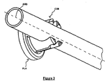
- la figure 2 représente une tringle circulaire de petit diamètre fixée sur le support,
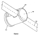
- la figure 3 représente une tringle circulaire de grand diamètre fixée sur le support,
- la figure 4 représente une tringle rectangulaire fixée sur le support,
- la figure 5 représente un capot ajusté sur une tringle circulaire de petit diamètre fixée sur le support,
- la figure 6 représente un capot présentant les passages destinés à des tringles circulaires de petit diamètre, et
- la figure 7 représente un capot présentant les passages destinés à des tringles circulaires de grand diamètre, ainsi qu'à des tringles rectangulaires.
Claims (29)
- Support comprenant :caractérisé en ce qu'il comporte également un deuxième moyen de fixation adapté à un second type de tringle différent dudit premier type.des moyens d'assujettissement de sa face arrière sur une structure fixe,un premier moyen de fixation adapté à un premier type de tringle,
- Support selon la revendication 1, caractérisé en ce que ledit premier moyen de fixation comporte un premier évidement cylindrique EVIi débouchant sur sa face frontale FAF, ledit évidement EVIi présentant une première section prédéterminée et un premier axe longitudinal AXEi parallèle à sa face arrière FAA.
- Support selon la revendication 2, caractérisé en ce que ledit premier moyen de fixation comporte de plus une première fente FENi perpendiculaire audit premier axe longitudinal AXEi et débouchant dans ledit premier évidement EVIi.
- Support selon la revendication 2, caractérisé en ce que ledit deuxième moyen de fixation comporte un second évidement cylindrique EVIj débouchant sur sa face frontale FAF, ledit évidement EVIj présentant une deuxième section prédéterminée différente de ladite première section et un deuxième axe longitudinal AXEj parallèle à ladite face arrière FAA.
- Support selon la revendication 4, caractérisé en ce que ledit deuxième moyen de fixation comporte de plus une seconde fente FENj perpendiculaire audit second axe longitudinal AXEj et débouchant dans ledit second évidement EVIj.
- Support selon l'une quelconque des revendications 4 ou 5, caractérisé en ce que ledit premier moyen de fixation est apte à recevoir des tringles à section circulaire de diamètre compris entre 6 et 8 millimètres, et en ce ledit deuxième moyen de fixation est apte à recevoir des tringles à section circulaire de diamètre compris entre 9 et 12 millimètres.
- Support selon l'une quelconque des revendications 1 à 3, caractérisé en ce que ledit premier moyen de fixation comporte un troisième évidement EVIk parallélépipédique coplanaire à ladite face arrière FAA et débouchant sur sa face frontale FAF, cet évidement présentant une troisième section prédéterminée et un troisième axe longitudinal AXEk.
- Support selon la revendication 7, caractérisé en ce que ledit deuxième moyen de fixation comporte de plus une troisième fente FENk perpendiculaire audit troisième axe longitudinal AXE, cette fente traversant ledit troisième évidement et débouchant sur ladite face frontale FAF.
- Support selon la revendication 8, caractérisé en ce que lesdits deuxième EVIj et troisième EVIk évidements sont coaxiaux.
- Support selon l'une quelconque des revendications 1 à 6, caractérisé en ce qu'il comporte également un troisième moyen de fixation.
- Support selon la revendication 10, caractérisé en ce que ledit troisième moyen de fixation comporte un quatrième évidement parallélépipédique coplanaire à ladite face arrière FAA et débouchant sur sa face frontale FAF, cet évidement présentant une quatrième section prédéterminée et un quatrième axe longitudinal.
- Support selon la revendication 11, caractérisé en ce que ledit troisième moyen de fixation comporte de plus une quatrième fente perpendiculaire audit quatrième axe longitudinal, cette fente traversant ledit quatrième évidement et débouchant sur ladite face frontale FAF.
- Support selon la revendication 12, caractérisé en ce que lesdits premier EVIi et quatrième évidements sont coaxiaux.
- Support selon l'une quelconque des revendications 10 à 13, caractérisé en ce qu'il comporte également un quatrième moyen de fixation.
- Support selon la revendication 14, caractérisé en ce que ledit quatrième moyen de fixation comporte un cinquième évidement parallélépipédique coplanaire à ladite face arrière FAA et débouchant sur sa face frontale FAF, cet évidement présentant une cinquième section prédéterminée et un cinquième axe longitudinal.
- Support selon la revendication 15, caractérisé en ce que ledit quatrième moyen de fixation comportent de plus une cinquième fente perpendiculaire audit cinquième axe longitudinal, cette fente traversant ledit cinquième évidement et débouchant sur ladite face frontale FAF.
- Support selon la revendication 16, caractérisé en ce qu'il est adapté à une tringle présentant une section rectangulaire de 12 par 8 millimètres.
- Support selon l'une quelconque des revendications 14 à 17, caractérisé en ce que lesdits deuxième EVIj et quatrième évidements sont coaxiaux.
- Support selon l'une quelconque des revendications précédentes, caractérisé en ce que certains au moins desdits moyens de fixation ont des axes AXEi, AXEj, AXEk coplanaires présentant un décalage angulaire.
- Support selon la revendication 19, caractérisé en ce que ledit décalage angulaire vaut 90°.
- Support selon l'une quelconque des revendications précédentes, caractérisé en ce que lesdits moyens de fixation sont agencés dans un corps cylindrique COR.
- Support selon la revendication 21, caractérisé en ce que ledit corps cylindrique COR est élastique, de sorte qu'il permette la fixation desdites tringles par emboítement.
- Support selon l'une quelconque des revendications précédentes, caractérisé en ce que lesdits moyens d'assujettissement consistent en un adhésif.
- Support selon l'une quelconque des revendications 1 à 22 caractérisé en ce que lesdits moyens d'assujettissement consistent en un orifice ORI, de sorte que ledit support puisse être vissé sur ladite structure.
- Support selon l'une quelconque des revendications précédentes, caractérisé en ce qu'il comporte un capot ajustable sur ledit corps COR et présentant des ouvertures adaptées auxdits moyens de fixation.
- Support selon la revendication 25, caractérisé en ce que ledit capot CAP comprend des moyens de clipsage sur ledit corps cylindrique COR.
- Support selon l'une quelconque des revendications 25 ou 26, caractérisé en ce que ledit capot CAP comprend des moyens de verrouillage pour bloquer une tringle en translation.
- Support selon l'une quelconque des revendications précédentes, caractérisé en ce que l'un au moins de ses éléments se présente sous la forme d'une zone prédécoupée.
- Support selon l'une quelconque des revendications précédentes, caractérisé en ce que l'un au moins desdits moyens de fixation présente, en regard des tringles, des reliefs prévus pour immobiliser une tringle en rotation et en translation.
Applications Claiming Priority (2)
| Application Number | Priority Date | Filing Date | Title |
|---|---|---|---|
| FR0315238A FR2864179B1 (fr) | 2003-12-23 | 2003-12-23 | Support de tringle a multiples moyens de fixation |
| FR0315238 | 2003-12-23 |
Publications (2)
| Publication Number | Publication Date |
|---|---|
| EP1548294A2 true EP1548294A2 (fr) | 2005-06-29 |
| EP1548294A3 EP1548294A3 (fr) | 2006-06-07 |
Family
ID=34531330
Family Applications (1)
| Application Number | Title | Priority Date | Filing Date |
|---|---|---|---|
| EP04030430A Withdrawn EP1548294A3 (fr) | 2003-12-23 | 2004-12-22 | Support de tringle |
Country Status (2)
| Country | Link |
|---|---|
| EP (1) | EP1548294A3 (fr) |
| FR (1) | FR2864179B1 (fr) |
Family Cites Families (4)
| Publication number | Priority date | Publication date | Assignee | Title |
|---|---|---|---|---|
| FR603790A (fr) * | 1924-12-22 | 1926-04-22 | Procédé de récupération de la matière grasse neutre dans les pâtes de neutralisation | |
| DE3211216C2 (de) * | 1982-03-26 | 1985-07-11 | Karl Heinz 5353 Mechernich Sander | Vorrichtung zur Befestigung eines Trägers mit Gardinenstange an einer Wand |
| DE29511027U1 (de) * | 1995-07-07 | 1995-09-14 | Fritsch, Eberhard Peter, 60486 Frankfurt | Vorrichtung zum Aufhängen einer Gardine, eines Vorhangs o.dgl. |
| GB2391456B (en) * | 2002-08-09 | 2004-10-06 | Piing Heh Entpr Co Ltd | Fixing structure for blind brackets and blind rod |
-
2003
- 2003-12-23 FR FR0315238A patent/FR2864179B1/fr not_active Expired - Fee Related
-
2004
- 2004-12-22 EP EP04030430A patent/EP1548294A3/fr not_active Withdrawn
Also Published As
| Publication number | Publication date |
|---|---|
| EP1548294A3 (fr) | 2006-06-07 |
| FR2864179B1 (fr) | 2006-03-17 |
| FR2864179A1 (fr) | 2005-06-24 |
Similar Documents
| Publication | Publication Date | Title |
|---|---|---|
| EP1644219B1 (fr) | Bloc projecteur pour vehicule automobile, et vehicule corresppondant | |
| FR2757318A1 (fr) | Connecteur electrique a montage sur un panneau | |
| WO2000017034A1 (fr) | Structure de support creuse de forme allongee comportant un flasque transversal a chacune de ses extremites | |
| FR2929815A1 (fr) | Etagere, en particulier pour des installations refrigerees. | |
| EP1713662B1 (fr) | Bouclier de pare-chocs de vehicule automobile | |
| EP2097960B1 (fr) | Support d'appareillage electrique | |
| FR3073722A1 (fr) | Etagere de rangement/decoration | |
| EP1548294A2 (fr) | Support de tringle | |
| FR2910732A1 (fr) | Support d'appareillage electrique a ouverture centrale modulable | |
| FR2888296A1 (fr) | Agencement de cage pour un ecrou cage. | |
| EP3115623B1 (fr) | Dispositif d'assemblage et de verrouillage | |
| WO2005038510A1 (fr) | Dispositif de plaquette nasale pour monture de lunettes | |
| EP1876681B1 (fr) | Boîte dotée d'un châssis de fixation pour organe électrique | |
| FR2649253A1 (fr) | Boite d'encastrement en deux parties, notamment pour appareillage electrique | |
| FR2766535A1 (fr) | Support amortissant les vibrations et procede pour son moulage | |
| EP1026356B1 (fr) | Panneau formé d'une plaque en verre, muni d'au moins un dispositif d'assemblage à une structure voisine | |
| FR3153102A1 (fr) | Dispositif de fixation d’un grillage sur un montant de clôture | |
| EP3928656B1 (fr) | Capot de protection | |
| EP1557502B1 (fr) | Elément de solidarisation réversible, panneaux et rangements mettant en oeuvre de tels éléments | |
| EP3593824B1 (fr) | Système de support invisible pour instruments médicaux à stériliser ou à nettoyer | |
| EP1475268A1 (fr) | Agencement pour le positionnement et la fixation d'un élément d'équipement sur un véhicule automobile | |
| FR2711907A1 (fr) | Etagère pour fixer une cabine de douche. | |
| EP4541664A1 (fr) | Enjoliveur pour peau de pare-chocs de véhicule automobile | |
| EP2355282A1 (fr) | Support d'appareillage et appareillage électrique comportant un tel support d'appareillage | |
| FR2844630A1 (fr) | Dispositif indicateur |
Legal Events
| Date | Code | Title | Description |
|---|---|---|---|
| PUAI | Public reference made under article 153(3) epc to a published international application that has entered the european phase |
Free format text: ORIGINAL CODE: 0009012 |
|
| AK | Designated contracting states |
Kind code of ref document: A2 Designated state(s): AT BE BG CH CY CZ DE DK EE ES FI FR GB GR HU IE IS IT LI LT LU MC NL PL PT RO SE SI SK TR |
|
| AX | Request for extension of the european patent |
Extension state: AL BA HR LV MK YU |
|
| 17P | Request for examination filed |
Effective date: 20051221 |
|
| PUAL | Search report despatched |
Free format text: ORIGINAL CODE: 0009013 |
|
| AK | Designated contracting states |
Kind code of ref document: A3 Designated state(s): AT BE BG CH CY CZ DE DK EE ES FI FR GB GR HU IE IS IT LI LT LU MC NL PL PT RO SE SI SK TR |
|
| AX | Request for extension of the european patent |
Extension state: AL BA HR LV MK YU |
|
| RIC1 | Information provided on ipc code assigned before grant |
Ipc: A47H 1/104 20060101ALI20060504BHEP Ipc: F16B 5/06 20060101ALI20060504BHEP Ipc: A47H 1/14 20060101ALI20060504BHEP Ipc: A47H 1/102 20060101AFI20060504BHEP |
|
| 17Q | First examination report despatched |
Effective date: 20061220 |
|
| AKX | Designation fees paid |
Designated state(s): AT BE BG CH CY CZ DE DK EE ES FI FR GB GR HU IE IS IT LI LT LU MC NL PL PT RO SE SI SK TR |
|
| STAA | Information on the status of an ep patent application or granted ep patent |
Free format text: STATUS: THE APPLICATION IS DEEMED TO BE WITHDRAWN |
|
| 18D | Application deemed to be withdrawn |
Effective date: 20070503 |