EP1548461B1 - Radar à impulsions - Google Patents
Radar à impulsions Download PDFInfo
- Publication number
- EP1548461B1 EP1548461B1 EP04029440A EP04029440A EP1548461B1 EP 1548461 B1 EP1548461 B1 EP 1548461B1 EP 04029440 A EP04029440 A EP 04029440A EP 04029440 A EP04029440 A EP 04029440A EP 1548461 B1 EP1548461 B1 EP 1548461B1
- Authority
- EP
- European Patent Office
- Prior art keywords
- signal
- circuit
- transmitting
- radar device
- pulse wave
- Prior art date
- Legal status (The legal status is an assumption and is not a legal conclusion. Google has not performed a legal analysis and makes no representation as to the accuracy of the status listed.)
- Expired - Lifetime
Links
- 238000004364 calculation method Methods 0.000 claims description 31
- 238000004891 communication Methods 0.000 claims description 23
- 238000006243 chemical reaction Methods 0.000 claims description 19
- 230000007274 generation of a signal involved in cell-cell signaling Effects 0.000 claims description 19
- 238000000926 separation method Methods 0.000 claims description 18
- 230000010355 oscillation Effects 0.000 claims description 9
- 230000005540 biological transmission Effects 0.000 description 12
- 238000005259 measurement Methods 0.000 description 10
- 238000010586 diagram Methods 0.000 description 8
- 238000012545 processing Methods 0.000 description 4
- 238000007493 shaping process Methods 0.000 description 3
- 230000003111 delayed effect Effects 0.000 description 2
- 238000001514 detection method Methods 0.000 description 2
- 230000010363 phase shift Effects 0.000 description 2
- 230000002459 sustained effect Effects 0.000 description 2
- 238000005284 basis set Methods 0.000 description 1
- 230000002596 correlated effect Effects 0.000 description 1
- 238000007599 discharging Methods 0.000 description 1
- PCHJSUWPFVWCPO-UHFFFAOYSA-N gold Chemical compound [Au] PCHJSUWPFVWCPO-UHFFFAOYSA-N 0.000 description 1
- 239000010931 gold Substances 0.000 description 1
- 229910052737 gold Inorganic materials 0.000 description 1
- 238000009434 installation Methods 0.000 description 1
- 238000000034 method Methods 0.000 description 1
- 230000000116 mitigating effect Effects 0.000 description 1
- 230000003287 optical effect Effects 0.000 description 1
- 230000002265 prevention Effects 0.000 description 1
- 230000001360 synchronised effect Effects 0.000 description 1
- 238000012546 transfer Methods 0.000 description 1
Images



Classifications
-
- G—PHYSICS
- G01—MEASURING; TESTING
- G01S—RADIO DIRECTION-FINDING; RADIO NAVIGATION; DETERMINING DISTANCE OR VELOCITY BY USE OF RADIO WAVES; LOCATING OR PRESENCE-DETECTING BY USE OF THE REFLECTION OR RERADIATION OF RADIO WAVES; ANALOGOUS ARRANGEMENTS USING OTHER WAVES
- G01S13/00—Systems using the reflection or reradiation of radio waves, e.g. radar systems; Analogous systems using reflection or reradiation of waves whose nature or wavelength is irrelevant or unspecified
- G01S13/87—Combinations of radar systems, e.g. primary radar and secondary radar
-
- G—PHYSICS
- G01—MEASURING; TESTING
- G01S—RADIO DIRECTION-FINDING; RADIO NAVIGATION; DETERMINING DISTANCE OR VELOCITY BY USE OF RADIO WAVES; LOCATING OR PRESENCE-DETECTING BY USE OF THE REFLECTION OR RERADIATION OF RADIO WAVES; ANALOGOUS ARRANGEMENTS USING OTHER WAVES
- G01S7/00—Details of systems according to groups G01S13/00, G01S15/00, G01S17/00
- G01S7/02—Details of systems according to groups G01S13/00, G01S15/00, G01S17/00 of systems according to group G01S13/00
- G01S7/023—Interference mitigation, e.g. reducing or avoiding non-intentional interference with other HF-transmitters, base station transmitters for mobile communication or other radar systems, e.g. using electro-magnetic interference [EMI] reduction techniques
-
- G—PHYSICS
- G01—MEASURING; TESTING
- G01S—RADIO DIRECTION-FINDING; RADIO NAVIGATION; DETERMINING DISTANCE OR VELOCITY BY USE OF RADIO WAVES; LOCATING OR PRESENCE-DETECTING BY USE OF THE REFLECTION OR RERADIATION OF RADIO WAVES; ANALOGOUS ARRANGEMENTS USING OTHER WAVES
- G01S13/00—Systems using the reflection or reradiation of radio waves, e.g. radar systems; Analogous systems using reflection or reradiation of waves whose nature or wavelength is irrelevant or unspecified
- G01S13/02—Systems using reflection of radio waves, e.g. primary radar systems; Analogous systems
- G01S13/06—Systems determining position data of a target
- G01S13/08—Systems for measuring distance only
- G01S13/10—Systems for measuring distance only using transmission of interrupted, pulse modulated waves
- G01S13/26—Systems for measuring distance only using transmission of interrupted, pulse modulated waves wherein the transmitted pulses use a frequency- or phase-modulated carrier wave
- G01S13/28—Systems for measuring distance only using transmission of interrupted, pulse modulated waves wherein the transmitted pulses use a frequency- or phase-modulated carrier wave with time compression of received pulses
- G01S13/284—Systems for measuring distance only using transmission of interrupted, pulse modulated waves wherein the transmitted pulses use a frequency- or phase-modulated carrier wave with time compression of received pulses using coded pulses
-
- G—PHYSICS
- G01—MEASURING; TESTING
- G01S—RADIO DIRECTION-FINDING; RADIO NAVIGATION; DETERMINING DISTANCE OR VELOCITY BY USE OF RADIO WAVES; LOCATING OR PRESENCE-DETECTING BY USE OF THE REFLECTION OR RERADIATION OF RADIO WAVES; ANALOGOUS ARRANGEMENTS USING OTHER WAVES
- G01S13/00—Systems using the reflection or reradiation of radio waves, e.g. radar systems; Analogous systems using reflection or reradiation of waves whose nature or wavelength is irrelevant or unspecified
- G01S13/88—Radar or analogous systems specially adapted for specific applications
- G01S13/93—Radar or analogous systems specially adapted for specific applications for anti-collision purposes
- G01S13/931—Radar or analogous systems specially adapted for specific applications for anti-collision purposes of land vehicles
-
- G—PHYSICS
- G01—MEASURING; TESTING
- G01S—RADIO DIRECTION-FINDING; RADIO NAVIGATION; DETERMINING DISTANCE OR VELOCITY BY USE OF RADIO WAVES; LOCATING OR PRESENCE-DETECTING BY USE OF THE REFLECTION OR RERADIATION OF RADIO WAVES; ANALOGOUS ARRANGEMENTS USING OTHER WAVES
- G01S7/00—Details of systems according to groups G01S13/00, G01S15/00, G01S17/00
- G01S7/02—Details of systems according to groups G01S13/00, G01S15/00, G01S17/00 of systems according to group G01S13/00
- G01S7/023—Interference mitigation, e.g. reducing or avoiding non-intentional interference with other HF-transmitters, base station transmitters for mobile communication or other radar systems, e.g. using electro-magnetic interference [EMI] reduction techniques
- G01S7/0234—Avoidance by code multiplex
-
- G—PHYSICS
- G01—MEASURING; TESTING
- G01S—RADIO DIRECTION-FINDING; RADIO NAVIGATION; DETERMINING DISTANCE OR VELOCITY BY USE OF RADIO WAVES; LOCATING OR PRESENCE-DETECTING BY USE OF THE REFLECTION OR RERADIATION OF RADIO WAVES; ANALOGOUS ARRANGEMENTS USING OTHER WAVES
- G01S13/00—Systems using the reflection or reradiation of radio waves, e.g. radar systems; Analogous systems using reflection or reradiation of waves whose nature or wavelength is irrelevant or unspecified
- G01S13/88—Radar or analogous systems specially adapted for specific applications
- G01S13/93—Radar or analogous systems specially adapted for specific applications for anti-collision purposes
- G01S13/931—Radar or analogous systems specially adapted for specific applications for anti-collision purposes of land vehicles
- G01S2013/93185—Controlling the brakes
-
- G—PHYSICS
- G01—MEASURING; TESTING
- G01S—RADIO DIRECTION-FINDING; RADIO NAVIGATION; DETERMINING DISTANCE OR VELOCITY BY USE OF RADIO WAVES; LOCATING OR PRESENCE-DETECTING BY USE OF THE REFLECTION OR RERADIATION OF RADIO WAVES; ANALOGOUS ARRANGEMENTS USING OTHER WAVES
- G01S13/00—Systems using the reflection or reradiation of radio waves, e.g. radar systems; Analogous systems using reflection or reradiation of waves whose nature or wavelength is irrelevant or unspecified
- G01S13/88—Radar or analogous systems specially adapted for specific applications
- G01S13/93—Radar or analogous systems specially adapted for specific applications for anti-collision purposes
- G01S13/931—Radar or analogous systems specially adapted for specific applications for anti-collision purposes of land vehicles
- G01S2013/9325—Radar or analogous systems specially adapted for specific applications for anti-collision purposes of land vehicles for inter-vehicle distance regulation, e.g. navigating in platoons
-
- G—PHYSICS
- G01—MEASURING; TESTING
- G01S—RADIO DIRECTION-FINDING; RADIO NAVIGATION; DETERMINING DISTANCE OR VELOCITY BY USE OF RADIO WAVES; LOCATING OR PRESENCE-DETECTING BY USE OF THE REFLECTION OR RERADIATION OF RADIO WAVES; ANALOGOUS ARRANGEMENTS USING OTHER WAVES
- G01S13/00—Systems using the reflection or reradiation of radio waves, e.g. radar systems; Analogous systems using reflection or reradiation of waves whose nature or wavelength is irrelevant or unspecified
- G01S13/88—Radar or analogous systems specially adapted for specific applications
- G01S13/93—Radar or analogous systems specially adapted for specific applications for anti-collision purposes
- G01S13/931—Radar or analogous systems specially adapted for specific applications for anti-collision purposes of land vehicles
- G01S2013/9327—Sensor installation details
- G01S2013/93271—Sensor installation details in the front of the vehicles
-
- G—PHYSICS
- G01—MEASURING; TESTING
- G01S—RADIO DIRECTION-FINDING; RADIO NAVIGATION; DETERMINING DISTANCE OR VELOCITY BY USE OF RADIO WAVES; LOCATING OR PRESENCE-DETECTING BY USE OF THE REFLECTION OR RERADIATION OF RADIO WAVES; ANALOGOUS ARRANGEMENTS USING OTHER WAVES
- G01S13/00—Systems using the reflection or reradiation of radio waves, e.g. radar systems; Analogous systems using reflection or reradiation of waves whose nature or wavelength is irrelevant or unspecified
- G01S13/88—Radar or analogous systems specially adapted for specific applications
- G01S13/93—Radar or analogous systems specially adapted for specific applications for anti-collision purposes
- G01S13/931—Radar or analogous systems specially adapted for specific applications for anti-collision purposes of land vehicles
- G01S2013/9327—Sensor installation details
- G01S2013/93275—Sensor installation details in the bumper area
-
- G—PHYSICS
- G01—MEASURING; TESTING
- G01S—RADIO DIRECTION-FINDING; RADIO NAVIGATION; DETERMINING DISTANCE OR VELOCITY BY USE OF RADIO WAVES; LOCATING OR PRESENCE-DETECTING BY USE OF THE REFLECTION OR RERADIATION OF RADIO WAVES; ANALOGOUS ARRANGEMENTS USING OTHER WAVES
- G01S7/00—Details of systems according to groups G01S13/00, G01S15/00, G01S17/00
- G01S7/003—Transmission of data between radar, sonar or lidar systems and remote stations
Definitions
- the present invention relates to a pulse wave radar device that uses a pulse wave. More specifically, it relates to an in-vehicle pulse wave radar device that prevents mistaken measurement of a pulse wave sent from any other radar device and utilizes the pulse wave radar device to enable communication.
- a variety of types of pulse wave radar devices which measure a distance to a target based on a lapse of time that has elapsed from a moment of transmission of a pulse wave to a moment of reception of a reflection from the target.
- a pulse wave radar device a lapse of time that has elapsed from a moment of emission of a transmitting wave to a moment of reception of a receiving wave is measured to thereby obtain a signal that is proportional to a distance from the pulse wave radar device to a target, according to which signal, the distance is calculated.
- a pulse wave radar device and the like for use in weather observation aimed at long-range measurement provides an antenna itself with sharp directivity and so scarcely interferes with any other pulse wave radar device in radio communication.
- An in-vehicle pulse wave radar device and the like aimed at short-range measurement provides it with wide directivity and so may be impossible to distinguish between a transmitting wave of its own and that of any other device in a case where a number of pulse wave radar devices are present in the same area.
- DE 44 42 189 A1 discloses a radar device for use in a vehicle including a receiver and a transmitter both connected to a signal processor and a clock unit.
- the radar may work with optical transmission or with high frequency transmission.
- Receiver and transmitter use several locally separated channels.
- the transmitted signal includes pulses for a distance measurement and pulses for the transmission of information. With the distance measured and the channel used the answering partner can be identified. A received answer is recognized by a predefined time delay to the emitted signal.
- DE 1 811 622 A1 discloses a pulsed Doppler radar device which can be used at the same time for the transmission of information.
- the information is coded into a pulse telegram which is transmitted with a carrier frequency different from the carrier frequency of the radar pulse directly in time before the radar pulse.
- reflected information pulses do not disturb the detection of the reflected Doppler shifted radar pulses.
- US 4,717,917 also discloses a pulsed Doppler radar system. Interference problems with alien radars transmitting essentially at the same frequency are avoided by changing the pulse repetition frequency in a random manner. The more random the PRF becomes, the better the likelihood is that alien radars of alike kind will be effectively rejected. There is no information transmitted with this radar system.
- US 5,497,162 discloses a method for mitigating interference among a plurality of radar sets.
- the radar signal of different radar devices may be varied based on a basis set, which can be to use differing frequencies, to use pulsed sinusoids with different pulse repetition frequencies, pulsed sinusoids with pseudo random pulse repetition frequencies or others.
- a basis set which can be to use differing frequencies, to use pulsed sinusoids with different pulse repetition frequencies, pulsed sinusoids with pseudo random pulse repetition frequencies or others.
- the direction in which the directional radar antenna is pointing is determined based on a compass bearing.
- DE 28 08 545 A1 and DE 28 08 544 A both disclose a pulsed Doppler radar device that allows a transmission of information.
- the information data is modulated onto the radar pulses with a binary coded pulse shift modulation.
- the information includes a synchronizing word in addition to the information data.
- the received signals are synchronized automatically.
- US 4,458,246 relates to a radar installation with a rotating antenna. Messages to surrounding weapons are transmitted by digitally coding every tenth radiated radar pulse. The modulation is effected by a phase shift of 180°. Depending on the angle of the rotateable radar antenna, the message is adapted to the receiver, e.g. the weapon, the beam is directed to.
- US 2002/0198632 A1 discloses the use of a noise radar for communication purposes only.
- the noise radar may be part of a vehicle based traffic system including GPS reception for a position determination.
- Each vehicle has a code which may be a 64 bit code.
- the vehicle continuously transmits this code using one frequency out of a determined frequency band.
- the communication is carrierless.
- the transmitted information may include an identification of the vehicle, position data, speed data or others.
- DE 196 00 802 A1 relates to a radar system for the identification of vehicles to be used in a toll system.
- a base station is provided with a primary radar for measuring the distance to the vehicle and the vehicle speed and with a secondary radar for sending questions to the vehicle.
- a mobile station which is mounted on the vehicle sends predefined answers upon reception of the questions.
- a switch is used to change between the primary and the secondary radar.
- DE 31 35 231 A1 discloses a communication system between fixed transceivers installed in short distances along a road and connected to the fixed telephone system and mobile stations mounted in vehicles.
- the information transmitted includes an identification number, a telephone number and voice data. Radio transmission is effectuated in statistically dispersed pulse packets.
- a radar device may be used as mobile station.
- JP 2002-277541 A discloses a radar device which has the distance-measuring pulses phase modulated by an identification number identifying the radar device. Upon reception of the reflected signal the pulse is demodulated and the identification number thus obtained compared with the identification number of the device. Only if the identification data coincides, the pulse is used for distance measuring.
- EP 0 676 650 A2 discloses a system with a transmitter/receiver-station and a transponder.
- the transmitter emits a message in form of a digitally coded telegram including synchronization bits, a preamble for a frame synchronisation and a load with the information.
- the preamble is used additionally as triggering pulse to start a distance measurement.
- the transponder answers with a response telegram.
- This answer telegram also includes a synchronization part, a preamble and a load for the information to be transmitted.
- the preamble is used as triggering pulse for stopping the distance measurement.
- the time between the two triggering pulses is measured and a fixed processing time inside the transponder is subtracted. Thus, the distance between transmitter/receiver station and transponder can be calculated.
- WO 02/061454 A1 discloses a radar device as equipment for a vehicle.
- the emitted radar signal is modulated with a pseudo noise code.
- the code is delayed and a signal in the receiving part is modulated with the delayed code. Phase Shift Keying and Amplitude Shift Keying are used.
- FIG. 1 is an explanatory block diagram of a configuration of the conventional pulse wave radar device.
- a reference numeral 81 indicates an information encoder for generating a code string obtained by encoding an identifier and an identification number that are used to identify a pulse wave radar device
- a reference numeral 82 indicates a transmitter for phase-modulating an information pulse and transmitting it
- a reference numeral 84 indicates an antenna for emitting a transmitting wave and receiving a receiving wave
- a reference numeral 85 indicates a receiver for receiving a receiving wave
- a reference numeral 86 indicates a phase detector for detecting a receiving wave
- a reference number 87 indicates an A/D converter for digitizing detected information
- a reference numeral 88 indicates a signal processor for collating information digitized by the A/D converter with a code string obtained by encoding an identifier and an identification number by the information encoder 81 and, only if they agree, measuring
- FIG. 2 is a timing chart of an input signal to the signal processor 88 for explaining operations of the conventional pulse wave radar device.
- the signal processor 88 compares between an identifier and an identification number that are received and those that are transmitted. In a case where the transmitted identifier and identification number are represented as code string "a”, if the received identifier and identification number constitute the code string "a”, the processor measures a delay time between the transmitted wave and the received wave, thereby calculating a distance to the target. If the received identifier and identification number constitute code string "b", the processor abandons information of the measured delay time utilizing that code string.
- the present invention has been developed, and it is an object of the present invention to provide a pulse wave radar device that can distinguish between a transmitting wave of its own and that of any other device even if a number of pulse wave radar devices are present in the same area, to reduce an amount of required high-speed signal processing, thereby measuring a distance to a target accurately.
- a pulse wave radar device of the present invention multiplexes a distance-measuring signal and a user data signal one on the other and converts it into a single pulse in each frame to use it as a transmitting signal. That is, it multiplexes the distance-measuring signal and the user data signal one on the other and converts it into a single pulse so that each frame may have in it the single pulse serving as a transmitting signal and a distance measurement region. As a result, some of the frames have no single pulse in them.
- the present invention provides a pulse wave radar device with the features of claim 1 comprising: a transmitting signal generation circuit for generating a transmitting signal in which a distance-measuring signal and a user data signal are multiplexed one on the other; an RZ code conversion circuit for generating an RZ propagation signal obtained by RZ-converting the transmitting signal from this transmitting signal generation circuit into a return-to-zero (RZ) code having a predetermined pulse width; a transmitting circuit for transmitting a transmitting wave obtained by intensity-modulating the RZ propagation signal from this RZ code conversion circuit at a local oscillation frequency; a transmitting antenna for emitting the transmitting wave sent from this transmitting circuit; a receiving antenna for receiving a receiving wave reflected by a target; and a receiving circuit for intensity-demodulating the receiving wave into the RZ propagation signal by detecting the receiving wave from this receiving antenna.
- a transmitting signal generation circuit for generating a transmitting signal in which a distance-measuring signal and a
- a pulse wave radar device not only for measurement of just a reciprocating propagation time but also for communication as well as prevention of radio interference with any other pulse wave radar devices.
- the pulse wave radar device further comprises a signal separation circuit for taking out an RZ propagation signal from the receiving circuit by separating it into the distance-measuring signal and the user data signal from each other.
- the present invention it is possible to measure a reciprocating propagation time by utilizing a distance-measuring signal and prevent radio interference with any other pulse wave radar devices by utilizing a user data signal.
- the pulse wave radar device of the present invention further comprises a time calculation circuit for detecting a lapse of time that has elapsed from a moment of emission of the transmitting wave to reception of the receiving wave to thereby calculate a reciprocating propagation time to a target.
- the present invention enables this pulse wave radar device to calculate a reciprocating propagation time to a target.
- the pulse wave radar device of the present invention is characterized in that the user data signal further includes identification data for identifying this pulse wave radar device.
- the present invention enables preventing radio interference with any other pulse wave radar devices by utilizing the identification data.
- the pulse wave radar device is further characterized by comprising a determination circuit for deciding a reciprocating propagation time calculated by the time calculation circuit to be valid if identification data separated by the signal separation circuit coincides with identification data multiplexed by the transmitting signal generation circuit.
- the present invention enables preventing a reciprocating propagation time calculated by the time calculation circuit from becoming indeterminate owing to determination of non-coincidence by the determination circuit.
- the time calculation circuit may hold a reciprocating propagation time determined before by the determination circuit to be valid because of coincidence.
- the user data signal may include communication information to be sent out of this pulse wave radar device.
- the present invention enables utilizing this pulse wave radar device as a transmitter for communication.
- a clock signal for a transmitting signal generated by the transmitting signal generation circuit may have a clock cycle of 10 MHz or less.
- the present invention enables detecting a maximum distance of up to 16 m or more from the pulse wave radar device to a target.
- a code included in an RZ propagation signal generated by the RZ code conversion circuit may have a pulse width of 2 nsec or less.
- the present invention enables detecting a minimum distance of 30 cm or less from the pulse wave radar device to a target.
- a pulse wave radar device can distinguish between a transmitting signal of its own and that of any other to thus reduce an amount of required high-speed signal processing, thus measuring a distance to a target accurately.
- the present embodiment provides a pulse wave radar device for transmitting a distance-measuring signal and a user data signal.
- this pulse wave radar device transmits in a form of a transmitting wave a transmitting signal, as RZ-converted, which is obtained by adding identification data as a user data signal to a distance-measuring signal and receives a receiving wave obtained when the transmitting wave is reflected by a target, thus measuring a reciprocating propagation time to the target.
- a transmitting signal to which communication information is added is transmitted as a user data signal in a form of a transmitting wave, it is possible to communicate with other devices by receiving a user data signal.
- FIG. 3 is an explanatory block diagram of an outlined configuration of the pulse wave radar device according to the present embodiment, in which a reference numeral 11 indicates a transmitting signal generation circuit for generating a transmitting signal obtained by adding identification data as the user data signal to the distance-measuring signal, a reference numeral 12 indicates an RZ code conversion circuit for generating an RZ propagation signal obtained by RZ-converting the transmitting signal into an RZ code having a predetermined pulse width, a reference numeral 13 indicates a transmitting circuit for transmitting a transmitting wave obtained by intensity-modulating the RZ propagation signal at a local oscillation frequency, a reference numeral 14 indicates a local oscillation circuit, a reference numeral 15 indicates a receiving circuit for detecting the receiving wave to intensity-demodulate into the RZ propagation signal, a reference numeral 21 indicates a transmitting antenna for emitting the transmitting wave, and a reference numeral 22 indicates a receiving
- a pulse wave radar device transmits at a constant period a transmitting signal obtained by adding identification data for identifying pulse wave radar devices to a distance-measuring signal so that any other pulse wave radar device can identify a receiving wave obtained when a transmitting wave of its own is reflected by a target.
- the transmitting signal generation circuit 11 generates as a transmitting signal a distance-measuring signal and identification data as a user data signal of its own.
- the identification data may be fixed data such as an identification number unique to the pulse wave radar device, an identification number set to a key of a vehicle in a case where the device is to be mounted in the vehicle, or an identification number set to a vehicle or such data as to be changed when the pulse wave radar device is mounted or an engine is started by utilizing an M-sequence code (maximum length linear shift register sequence code), a gold code, a Barker code, etc.
- M-sequence code maximum length linear shift register sequence code
- gold code a Barker code
- a transmitting signal from the transmitting signal generation circuit 11 is output to the RZ code conversion circuit 12.
- the RZ code conversion circuit 12 RZ-converts each of codes of the transmitting signal into an RZ code having a predetermined pulse width.
- the RZ code conversion circuit 12 outputs an RZ propagation signal thus RZ-converted, to the transmitting circuit 13.
- the transmitting circuit 13 intensity-modulates the RZ-converted RZ propagation signal at a local oscillation frequency from the local oscillation circuit 14 and emits it as a pulse code through the transmitting antenna 21.
- this pulse wave radar device may be provided with a time calculation circuit for detecting a lapse of time that has elapsed from a moment of transmission of the RZ propagation signal to a moment of its reception to thereby calculate a reciprocating propagation time to the target. From the reciprocating propagation time, a distance to the target can be calculated.
- any other pulse wave radar device Even if the same receiving wave is received by any other pulse wave radar device in that while, it can detect identification data included in the intensity-demodulated into RZ propagation to determine whether it coincides with identification data itself has sent. If non-coincidence is determined, the pulse wave radar device stops calculation of the reciprocating propagation time or abandons its calculated value to prevent calculation of a wrong distance to the target.
- the transmitting antenna 21 and the receiving antenna 22 are illustrated as separated in FIG. 3, they may be combined into one antenna for transmission and reception. Further, if the antenna has directivity, a reciprocating propagation time to the target in a specific direction can be calculated and if it has a wide directivity, a reciprocating propagation time to the target over a wide angle can be calculated.
- the antenna can be mounted anywhere. If it is to be mounted in a vehicle, it is equipped in a front bumper, in an engine room or in front of a driver's seat. This holds true also with the following embodiments.
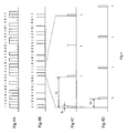
- FIG. 4 is an explanatory timing chart of operations of the pulse wave radar device according to the present embodiment.
- FIG. 4A indicates a timing chart of operations of a transmitting signal generated by the transmitting signal generation circuit.
- a sequential code string starting with "11010100100” is exemplified.
- eleven codes of "11010100100” are utilized as identification data and the following four codes of "1111" are utilized for measuring the distance.
- FIG. 4B indicates a timing chart of operations of an RZ propagation signal obtained by RZ-converting the transmitting signal shown in FIG. 4A by the RZ code conversion circuit.
- FIG. 4C expands a portion of a sequential distance-measuring signal of FIG. 4B.
- Tc indicates a clock signal period of the transmitting signal
- Tr indicates a pulse width of a code of the RZ propagation signal.
- the RZ code conversion circuit outputs the RZ propagation signal having a pulse width Tr at clock signal period Tc.
- FIG. 4D expands a portion of a sequential distance-measuring signal, which is the RZ propagation signal intensity-demodulated by the receiving circuit.
- delay time difference Td has occurred between a pulse of the sequential distance-measuring signal of FIG. 4C and that of the sequential distance-measuring signal of FIG. 4D. It means that the target is distant by as much as a distance that corresponds to the delay time difference Td.
- communication information may be included as a user data signal in a transmitting signal.
- Communication information for transfer of communication information is input to the transmitting signal generation circuit 11 in FIG. 3 and, following transmission of the distance-measuring signal "1111", the communication information "010100011011010011" is transmitted in FIG. 4A.
- Such communication information may be a CAN BUS signal.
- the pulse wave radar device can be utilized also as a device for transmitting communication information.
- identification data and communication information in a transmitting signal and using the identification data to identify a pulse wave radar device or a vehicle it can be transmitted as communication information to which information of a sender is added.
- a range indicated by clock signal period Tc in FIG. 4C is referred to as a frame.
- each of pulses of an RZ propagation signal is allocated which is obtained by RZ-converting a transmitting signal including identification data and a distance-measuring signal by the RZ code conversion circuit. Therefore, "1" is not always allocated at the beginning of each frame.
- each frame has comprised the beginning eleven pulses as identification data, followed by four pulses as a distance-measuring signal and eighteen pulses as communication information in this order, the present invention is not limited to it. If the identification data has more pulses, identification is improved correspondingly. If the distance-measuring signal has more pulses, a measurement accuracy of a reciprocating propagation time is increased correspondingly. If the communication information has more pulses, a transmission speed is increased correspondingly. Further, although the present embodiment has allocated identification data, a distance-measuring signal, and communication information in a concentrated manner, they may be dispersed from each other in allocation. Furthermore, the distance-measuring signal may be utilized as a synchronizing header for the identification data or the communication information.
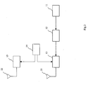
- FIG. 5 shows another embodiment of a pulse wave radar device. Components that are the same as or correspond to those of FIG. 3 are indicated by the same reference symbols and so their description is omitted.
- This pulse wave radar device is different from that shown in FIG. 3 in that it is provided with a signal separation circuit 16.
- the signal separation circuit 16 takes out a distance-measuring signal and a user data signal by separating them from an RZ propagation signal which is intensity-demodulated by a receiving circuit 15. By utilizing the distance-measuring signal, it is possible to measure a reciprocating propagation time to a target. Further, if identification data is included in the user data signal, it can determine whether identification data which itself has sent coincides with that included in the RZ propagation signal which is intensity-demodulated.
- FIG. 6 shows a further embodiment of a pulse wave radar device. Components that are the same as or correspond to those of FIG. 5 are indicated by the same reference symbols and so their description is omitted.
- This pulse wave radar device is different from that shown in FIG. 5 in that it is provided with a time calculation circuit 17.
- the time calculation circuit 17 detects a lapse of time that has elapsed from a moment of emission of a transmitting wave by the pulse wave radar device to a moment of reception of a receiving wave to thereby calculate a reciprocating propagation time to a target.
- the time calculation circuit 17 detects a lapse of time that has elapsed from a moment when an RZ code conversion circuit 12 output an RZ propagation signal through moments when a transmitting circuit 13 transmitted a transmitting wave obtained by intensity-modulating the RZ propagation signal from the RZ code conversion circuit 12 at a local oscillation frequency, the transmitting wave from the transmitting circuit 13 was radiated from a transmitting antenna 21, a receiving wave reflected by the target was received at a receiving antenna 22, the receiving wave from the receiving antenna 22 was detected by a receiving circuit 15 to intensity-demodulate into the RZ propagation signal, and a distance-measuring signal and a user data signal were taken out after being separated from the RZ propagation signal intensity-demodulated by the signal separation circuit 16 to a moment when the RZ propagation signal was input from the signal separation circuit 16 to the time calculation circuit 17, thus calculating a reciprocating propagation time to the target.
- a distance to the target can be calculated from the reciprocating propagation time.
- the time calculation circuit 17 measures propagation delay times through various circuits in the pulse wave radar device beforehand and converts a detected time into a lapse of time that has elapsed from a moment of emission of a transmitting wave by the pulse wave radar device to a moment of reception of a receiving wave, thereby calculating a reciprocating propagation time to the target.
- Time difference Td has occurred between a pulse of an RZ propagation signal output by the RZ code conversion circuit 12 of FIG. 4C and that of the RZ propagation signal input from the signal separation circuit 16 to the time calculation circuit 17 of FIG. 4D. It means that the target is distant by as much as a distance that corresponds to the time difference Td.
- the distance to the target can be calculated from Equation (1).
- the time calculation circuit can employ a pulse count system or a flip-flop circuit system.
- a moment when a distance-measuring signal is output by the RZ code conversion circuit 12 is assumed to be a start timing and a moment when the distance-measuring signal is output by the signal separation circuit 16 is assumed to be a stop timing, to detect the number of pulses counted between these two timings, thus calculating a lapse of time.
- FIG. 7 shows part of a configuration of the time calculation circuit 17 shown in FIG. 6 as an example of the flip-flop circuit system.
- a reference numeral 17 indicates the time calculation circuit
- a reference numeral 31 indicates an input terminal
- a reference numeral 32 indicates an amplifier
- a reference numeral 33 indicates a waveform shaping circuit
- a reference numeral 34 indicates another input terminal
- a reference numeral 35 indicates a flip-flop circuit
- a reference numeral 36 indicates a low-pass filter
- a reference numeral 37 indicates an output terminal.
- An output of the signal separation circuit is input to the input terminal 31, is amplified by the amplifier 32, and then has its waveform shaped by the waveform shaping circuit 33.
- the flip-flop circuit 35 is of a set/reset type.
- a signal from the RZ code conversion circuit is input from the input terminal 34 to a SET terminal of the flip-flop circuit 35.
- a signal from the waveform shaping circuit 33 is input to a RESET terminal of the flip-flop circuit 35.
- the clock cycle Tp is 10 MHz or less.
- a maximum detectable distance from the pulse wave radar device to the target is 16 m
- the time necessary for the pulse code to go to the target and return back is 106 nsec.
- a clock signal having a period of 106 nsec has a clock signal frequency of 9.4 MHz. Therefore, if the clock cycle for a transmitting signal is 10 MHz or less, a maximum detectable distance of 16 m or more can be assured.
- the pulse width Tr of a code of the RZ propagation signal is 2 nsec or less.
- a minimum detectable distance from the pulse wave radar device to the target is 30 cm, if transmission of one pulse code is not completed before it is transmitted, reflected by the target positioned at a distance of 30 cm, and returned back, the target at the minimum detectable distance cannot be detected. If the minimum detectable distance is 30 cm, the time necessary for the pulse code to go to the target and return back is 2 nsec. Therefore, if the pulse width of the code of the RZ propagation signal is 2 nsec or less, a minimum detectable distance of 30 cm or less can be assured.
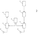
- FIG. 8 shows a still further embodiment of a pulse wave radar device. Components that are the same as or correspond to those of FIG. 6 are indicated by the same reference symbols and so their description is omitted.
- This pulse wave radar device is different from that shown in FIG. 6 in that it is provided with a determination circuit 18.
- the determination circuit 18 receives, from an RZ code conversion circuit 12, identification data transmitted by itself and further receives from a signal separation circuit 16 identification data included in an RZ propagation signal which is intensity-demodulated, thereby detecting coincidence or non-coincidence between the identification data transmitted by itself and that included in the intensity-demodulated RZ propagation signal.
- the radar device can distinguish between a reflected wave which itself has transmitted and a transmitting wave which any other radar device has transmitted or a reflected wave owing to this transmitting wave. For example, if the identification data that itself has transmitted is "11010100100" shown in FIG. 4B and identification data included in an RZ propagation signal intensity-demodulated by the receiving circuit is the same as that, it can be determined to be the identification data that itself has transmitted. If it is any other identification data, it is determined to be a transmitting wave from any other radar device or a reflected wave owing to this transmitting wave.
- the determination circuit 18 determines coincidence between identification data separated by the signal separation circuit 16 and that which is multiplexed by the transmitting signal generation circuit 11, it determines a reciprocating propagation time calculated by the time calculation circuit 17 to be valid by using the distance-measuring signal included in a relevant RZ propagation signal.
- the determination circuit 18 might as well make a determination based on complete coincidence between identification data separated by the signal separation circuit 16 and that multiplexed by the transmitting signal generation circuit 11.
- a determination may be made on the basis of coincidence within a tolerance taking into account an error of the receiving circuit. That is , the tolerance may be of a degree at which a correlation is detected.
- the cases of deciding a low correlation include a case other than complete coincidence.
- the time calculation circuit 17 sustains a reciprocating propagation time calculated before because of a high correlation. It is thus possible to prevent a reciprocating propagation time calculated by the time calculation circuit 17 from becoming indeterminate owing to a determination of a low correlation.
- FIG. 9 explains a timing chart of operations of the determination circuit 18 when it determines non-coincidence between identification data separated by the signal separation circuit 16 and that multiplexed by the transmitting signal generation circuit 11 in the case of a flip-flop circuit system.
- the distance-measuring signal shown in FIG. 4A is included in the identification data and this sequence of data pieces is used as the identification data to detect whether they coincide or not.
- FIG. 9A expands a portion of a sequential distance-measuring signal. In it, Tc indicates a clock signal period of the transmitting signal and Tr indicates a pulse width of a code of the RZ propagation signal.
- Tc indicates a clock signal period of the transmitting signal
- Tr indicates a pulse width of a code of the RZ propagation signal.
- FIG. 9B expands a portion of a sequential distance-measuring signal, which is the RZ propagation signal that is intensity-demodulated by the receiving circuit.
- FIG. 9C shows an output of a flip-flop circuit 35 shown in FIG. 7 and
- FIG. 9D shows an output of a low-pass filter 36 shown in FIG. 7.
- the device stops operations of the flip-flop circuit 35 or charging/discharging of the low-pass filter 36 and the time calculation circuit 17 sustains a reciprocating propagation time determined by the determination circuit 18 to be valid because of coincidence before.
- FIG. 9D the same output is sustained as indicated by a dotted line portion.
- the determination circuit 18 may detect coincidence/non-coincidence based on only identification data. In this case, after the determination circuit 18 determines non-coincidence, the time calculation circuit 17 may sustain and output a reciprocating propagation time determined to be valid by the determination circuit 18 before.
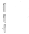
- circuits that handle the RZ propagation signal, the transmitting wave, and the receiving wave in the pulse wave radar device shown in FIG. 8 operate at a high speed
- the other circuits operate at a relatively low speed, thus enabling suppressing power consumption to a low level.
- the pulse wave radar device can be utilized not only as an in-vehicle one but also as a fixed type one where a plurality of pulse wave radar devices is used simultaneously.
Landscapes
- Engineering & Computer Science (AREA)
- Radar, Positioning & Navigation (AREA)
- Remote Sensing (AREA)
- Computer Networks & Wireless Communication (AREA)
- Physics & Mathematics (AREA)
- General Physics & Mathematics (AREA)
- Electromagnetism (AREA)
- Radar Systems Or Details Thereof (AREA)
Claims (4)
- Appareil radar à ondes à impulsions, comportant :un circuit de génération d'un signal d'émission (11) pour générer un signal d'émission, dans lequel un signal de mesure de distance et un signal de données d'utilisateur sont multiplexés dans le temps, le signal de données d'utilisateur incluant des informations de communication qui doivent être transmises à un extérieur de l'appareil radar à ondes à impulsions ;un circuit de conversion de code RZ (12) pour générer un signal de propagation RZ obtenu par la conversion, du type RZ, du signal d'émission du circuit de génération d'un signal d'émission en un code RZ présentant une largeur d'impulsion prédéterminée ;un circuit émetteur (13) pour émettre une onde d'émission obtenue par la modulation de l'intensité du signal de propagation RZ provenant du circuit de conversion de code RZ à une fréquence d'oscillation locale ;une antenne émettrice (21) pour émettre l'onde d'émission envoyée par le circuit d'émission ;une antenne réceptrice (22) pour recevoir une onde de réception réfléchie par une cible ;un circuit récepteur (15) pour démoduler l'intensité de l'onde de réception en un signal de propagation RZ en détectant l'onde de réception de l'antenne réceptrice ;un circuit de séparation de signaux (16) pour séparer le signal de propagation RZ provenant du circuit récepteur (15) de manière à obtenir le signal de mesure de distance et le signal de données d'utilisateur ;un circuit de calcul de temps (17) pour détecter un laps de temps qui s'est écoulé entre un moment d'émission de l'onde d'émission et un moment de réception du signal de réception pour ainsi calculer un temps de propagation aller-retour vers la cible, caractérisé en ce quele signal de données d'utilisateur comporte en outre des données d'identification identifiant l'appareil radar à ondes à impulsions, et en ce que l'appareil radar à ondes à impulsions présente en outreun circuit de détermination (18) pour décider qu'un temps de propagation aller-retour, calculé par le circuit de calcul de temps (17), est valable lorsque des données d'identification séparées par le circuit de séparation de signaux (16) coïncident avec des données d'identification multiplexées par le circuit de génération d'un signal d'émission (11).
- Appareil radar à ondes à impulsions selon la revendication 1, dans lequel lorsque le circuit de détermination (18) détermine que des données d'identification séparées par le circuit de séparation de signaux (16) ne coïncident pas avec des données d'identification multiplexées par le circuit de génération d'un signal d'émission (11), le circuit de calcul de temps (17) maintient la validité d'un temps de propagation aller-retour déterminé par le circuit de détermination (18) en raison d'une coïncidence précédente.
- Appareil radar à ondes à impulsions selon la revendication 1 ou 2, dans lequel un cycle d'horloge d'un signal d'émission émis par le circuit de génération d'un signal d'émission (11) est égal ou inférieur à 10 MHz.
- Appareil radar à ondes à impulsions selon la revendication 1 ou 2, dans lequel une largeur d'impulsion d'un code d'un signal de propagation RZ généré par le circuit de conversion de code RZ (12) est égale ou inférieure à 2 nsec.
Applications Claiming Priority (2)
| Application Number | Priority Date | Filing Date | Title |
|---|---|---|---|
| JP2003424874A JP2005181193A (ja) | 2003-12-22 | 2003-12-22 | パルス波レーダー装置 |
| JP2003424874 | 2003-12-22 |
Publications (2)
| Publication Number | Publication Date |
|---|---|
| EP1548461A1 EP1548461A1 (fr) | 2005-06-29 |
| EP1548461B1 true EP1548461B1 (fr) | 2008-01-30 |
Family
ID=34544934
Family Applications (1)
| Application Number | Title | Priority Date | Filing Date |
|---|---|---|---|
| EP04029440A Expired - Lifetime EP1548461B1 (fr) | 2003-12-22 | 2004-12-13 | Radar à impulsions |
Country Status (5)
| Country | Link |
|---|---|
| US (1) | US7012562B2 (fr) |
| EP (1) | EP1548461B1 (fr) |
| JP (1) | JP2005181193A (fr) |
| KR (1) | KR100748417B1 (fr) |
| DE (1) | DE602004011597T2 (fr) |
Families Citing this family (24)
| Publication number | Priority date | Publication date | Assignee | Title |
|---|---|---|---|---|
| DE10256620A1 (de) * | 2002-12-03 | 2004-07-08 | Daimlerchrysler Ag | Radarsystem mit integrierter Datenübertragung |
| US7866394B2 (en) * | 2003-02-27 | 2011-01-11 | Halliburton Energy Services Inc. | Compositions and methods of cementing in subterranean formations using a swelling agent to inhibit the influx of water into a cement slurry |
| KR100720878B1 (ko) * | 2004-02-24 | 2007-05-23 | 티디케이가부시기가이샤 | 펄스파 레이더 장치 |
| JP2006064644A (ja) * | 2004-08-30 | 2006-03-09 | Tdk Corp | パルス波レーダー装置 |
| JP2006184130A (ja) * | 2004-12-27 | 2006-07-13 | Tdk Corp | レーダー装置 |
| JP4687239B2 (ja) * | 2005-05-19 | 2011-05-25 | 三菱電機株式会社 | 送受信装置及び送受信方法 |
| JP2007132768A (ja) * | 2005-11-10 | 2007-05-31 | Hitachi Ltd | 通信機能を有する車載レーダー装置 |
| KR100951529B1 (ko) * | 2007-12-21 | 2010-04-08 | 재단법인대구경북과학기술원 | 초광대역 차량용 레이더 시스템 구동 방법 및 초광대역차량용 레이더 시스템 |
| DE102008050988A1 (de) * | 2008-09-01 | 2010-03-04 | Gerd Reime | Identifikationselement mit einem optischen Transponder |
| RU2542330C1 (ru) * | 2013-10-23 | 2015-02-20 | Федеральное государственное бюджетное образовательное учреждение высшего профессионального образования Томский государственный университет систем управления и радиоэлектроники | Способ пассивного обнаружения воздушных объектов |
| JP6495771B2 (ja) * | 2015-07-10 | 2019-04-03 | 株式会社東芝 | 気象レーダ装置、並びに、気象レーダ装置の制御装置、制御方法、及び制御プログラム |
| EP3165944B1 (fr) * | 2015-11-04 | 2022-04-20 | Nxp B.V. | Authentification de communication intégrée |
| EP3165940B1 (fr) | 2015-11-04 | 2022-04-20 | Nxp B.V. | Authentification de communication intégrée |
| US10845477B2 (en) | 2017-05-10 | 2020-11-24 | Google Llc | Power management using a low-power radar |
| US10754005B2 (en) | 2017-05-31 | 2020-08-25 | Google Llc | Radar modulation for radar sensing using a wireless communication chipset |
| US10795009B2 (en) | 2017-05-31 | 2020-10-06 | Google Llc | Digital beamforming for radar sensing using wireless communication chipset |
| US10782390B2 (en) | 2017-05-31 | 2020-09-22 | Google Llc | Full-duplex operation for radar sensing using wireless communication chipset |
| TWI681644B (zh) * | 2017-05-31 | 2020-01-01 | 美商谷歌有限責任公司 | 使用無線通訊晶片組之用於雷達感測之全雙工操作 |
| US11609337B2 (en) * | 2017-08-25 | 2023-03-21 | Baraja Pty Ltd | Estimation of spatial profile of environment |
| CN113614676B (zh) | 2019-05-20 | 2024-03-26 | 谷歌有限责任公司 | 用于提供多模式界面的基于移动设备的雷达系统及其方法 |
| CN113632046A (zh) | 2019-06-17 | 2021-11-09 | 谷歌有限责任公司 | 用于将不同功率模式应用于多模式界面的基于移动设备的雷达系统 |
| KR102302885B1 (ko) * | 2020-06-18 | 2021-09-17 | 한화시스템 주식회사 | 레이더에서 데이터를 처리하는 장치 및 방법 |
| CN111965647B (zh) * | 2020-08-05 | 2021-04-27 | 江苏科技大学 | 基于雷达通信一体化的路况探测方法 |
| CN114035183B (zh) * | 2021-11-05 | 2025-08-26 | 深圳市赛盈地脉技术有限公司 | 基于脉冲的雷达数据的定位方法、装置、设备和介质 |
Family Cites Families (33)
| Publication number | Priority date | Publication date | Assignee | Title |
|---|---|---|---|---|
| US3858205A (en) * | 1972-10-06 | 1974-12-31 | Sperry Rand Corp | Base-band precollision sensor with time domain gating for preventing false responses |
| US4156874A (en) * | 1977-11-21 | 1979-05-29 | Kopis Floyd B | Anti-collision vehicle radar system |
| DE2808545C2 (de) * | 1978-02-28 | 1984-10-25 | Siemens AG, 1000 Berlin und 8000 München | Kombinierte Radar- und Nachrichtenübertragungseinrichtung |
| DE2808544C2 (de) * | 1978-02-28 | 1984-10-25 | Siemens AG, 1000 Berlin und 8000 München | Kombinierte Radar- und Nachrichtenübertragungseinrichtung |
| SE421250C (sv) * | 1978-09-12 | 1983-05-09 | Ericsson Telefon Ab L M | Radaranleggning |
| DE3135231A1 (de) | 1981-09-05 | 1983-04-07 | Standard Elektrik Lorenz Ag, 7000 Stuttgart | Nachrichtenuebertragungssystem |
| US4717917A (en) * | 1985-06-26 | 1988-01-05 | Rockwell International Corporation | Alien radar suppression circuit |
| JPH0396138A (ja) * | 1989-09-08 | 1991-04-22 | Clarion Co Ltd | 符号発生装置 |
| DE4120479A1 (de) * | 1991-06-21 | 1992-12-24 | Standard Elektrik Lorenz Ag | Dauerstrich-radargeraet, zusaetzlich als sender fuer die informationsuebertragung verwendbar |
| JP2891811B2 (ja) * | 1991-11-26 | 1999-05-17 | ダイハツ工業株式会社 | 自動車の距離計測方法 |
| JPH0784035A (ja) * | 1993-09-16 | 1995-03-31 | Japan Radio Co Ltd | 自動車用前方警戒レーダ装置 |
| EP0676650B1 (fr) | 1994-04-06 | 2002-01-30 | EADS Deutschland Gmbh | Méthode de mesure de distance à l'aide d'une liaison radio, et appareil de mise en oeuvre de la méthode |
| EP0714035A1 (fr) * | 1994-11-24 | 1996-05-29 | The Furukawa Electric Co., Ltd. | Dispositif radar |
| DE4442189C2 (de) * | 1994-11-28 | 2002-04-18 | Martin Spies | System zur Abstandsmessung und selektiven Informationsübertragung für Kfz-Anwendung |
| US5497162A (en) * | 1995-01-09 | 1996-03-05 | Northrop Grumman Corporation | Radar signal selection based upon antenna bearing |
| US5594447A (en) | 1995-01-11 | 1997-01-14 | Mitsubishi Denki Kabushiki Kaisha | Moving target identifying system in a base station radar unit for specifying information about moving targets carrying a mobile station radar unit |
| JPH08285942A (ja) * | 1995-04-11 | 1996-11-01 | Yazaki Corp | 車両用レーザレーダ |
| US6720920B2 (en) * | 1997-10-22 | 2004-04-13 | Intelligent Technologies International Inc. | Method and arrangement for communicating between vehicles |
| US5923280A (en) * | 1997-01-17 | 1999-07-13 | Automotive Systems Laboratory, Inc. | Vehicle collision radar with randomized FSK wave form |
| FR2760535B1 (fr) * | 1997-03-04 | 1999-05-28 | Thomson Csf | Dispositif de reduction de bruit dans un recepteur radar |
| JPH10271557A (ja) * | 1997-03-21 | 1998-10-09 | Kokusai Electric Co Ltd | ランダムアクセス信号受信回路 |
| JP3035817B2 (ja) * | 1997-07-11 | 2000-04-24 | アンリツ株式会社 | クロック再生装置 |
| JP3818349B2 (ja) * | 1998-03-31 | 2006-09-06 | オムロン株式会社 | レーダ、レーダの信号処理方法、レーダの通信方法および記録媒体 |
| JPH11308658A (ja) * | 1998-04-24 | 1999-11-05 | Oki Electric Ind Co Ltd | 移動局の位置検出方法、並びに移動局、基地局及び移動通信システム |
| JP3899708B2 (ja) * | 1998-10-16 | 2007-03-28 | 株式会社デンソー | 距離測定装置 |
| US6094160A (en) * | 1999-06-10 | 2000-07-25 | Delco Electronics Corp. | Interference rejection method for an automotive radar CW/ICC system |
| DE10005558A1 (de) * | 2000-02-09 | 2001-08-23 | Bosch Gmbh Robert | Vorrichtung zur Datenübertragung im Kraftfahrzeug |
| JP2002055155A (ja) * | 2000-08-11 | 2002-02-20 | Japan Radio Co Ltd | レーダ装置 |
| DE10104022A1 (de) * | 2001-01-31 | 2002-08-01 | Bosch Gmbh Robert | Radareinrichtung und Verfahren zum Codieren einer Radareinrichtung |
| DE10108582A1 (de) * | 2001-02-22 | 2002-09-05 | Bosch Gmbh Robert | Verfahren zum Erkennen gestörter Zustände einer Radareinrichtung und Radareinrichtung |
| JP2002277541A (ja) * | 2001-03-15 | 2002-09-25 | Mitsubishi Electric Corp | レーダ装置 |
| JP2003174368A (ja) * | 2001-12-06 | 2003-06-20 | Sony Corp | 無線通信装置、送信出力制御方法、記憶媒体、並びにコンピュータ・プログラム |
| JP2005106603A (ja) * | 2003-09-30 | 2005-04-21 | Tdk Corp | パルス波レーダー装置 |
-
2003
- 2003-12-22 JP JP2003424874A patent/JP2005181193A/ja active Pending
-
2004
- 2004-11-22 US US10/992,724 patent/US7012562B2/en not_active Expired - Fee Related
- 2004-12-13 EP EP04029440A patent/EP1548461B1/fr not_active Expired - Lifetime
- 2004-12-13 DE DE602004011597T patent/DE602004011597T2/de not_active Expired - Lifetime
- 2004-12-22 KR KR1020040110561A patent/KR100748417B1/ko not_active Expired - Fee Related
Also Published As
| Publication number | Publication date |
|---|---|
| DE602004011597D1 (de) | 2008-03-20 |
| US20050134502A1 (en) | 2005-06-23 |
| DE602004011597T2 (de) | 2009-02-05 |
| JP2005181193A (ja) | 2005-07-07 |
| KR20050063739A (ko) | 2005-06-28 |
| KR100748417B1 (ko) | 2007-08-10 |
| EP1548461A1 (fr) | 2005-06-29 |
| US7012562B2 (en) | 2006-03-14 |
Similar Documents
| Publication | Publication Date | Title |
|---|---|---|
| US7012562B2 (en) | Pulse wave radar device | |
| EP1119777B1 (fr) | Dispositif de mesure de proximite | |
| US6693582B2 (en) | Radar device and method for coding a radar device | |
| JP2942923B2 (ja) | ランダムパルス型レーダー装置 | |
| EP1071967B1 (fr) | Systeme et procede de determination de position par radio impulsions | |
| US9664777B2 (en) | Radar device | |
| US20070241955A1 (en) | System Having Two or More Sensors | |
| EP0940691A2 (fr) | Procédé et appareil de détection de distance | |
| US20030093195A1 (en) | Train control system and method therefor | |
| ZA200400693B (en) | Method of determining the position of a target using transmitters of opportunity. | |
| JPH03231184A (ja) | Tcs監視システムにおける同期フルーツを低減する装置 | |
| US20220271793A1 (en) | Communication device and operating method | |
| CN100412566C (zh) | 用于测量距离的方法和装置 | |
| KR20010052576A (ko) | 다수의 원격 송신기와의 통신 시스템 및 통신 방법 | |
| US7345624B2 (en) | Pulse wave radar device | |
| JP2005106603A (ja) | パルス波レーダー装置 | |
| JP2014059284A (ja) | 相互間距離測定機能を付加した安全運転支援装置 | |
| CN111123249A (zh) | 一种基于tdma网络的测距方法和系统 | |
| CN1727914B (zh) | 倒车雷达装置 | |
| US20190204444A1 (en) | Optical Telemetry System | |
| US6243025B1 (en) | Moving body detection system | |
| US11477061B2 (en) | Wireless digital communication method and system for the communication between two electronic devices of an industrial apparatus | |
| JPH08268284A (ja) | 質問装置、応答装置及び列車追突防止用監視システム | |
| EP3709057A1 (fr) | Communications v2x améliorées par radar | |
| JPH0257875B2 (fr) |
Legal Events
| Date | Code | Title | Description |
|---|---|---|---|
| PUAI | Public reference made under article 153(3) epc to a published international application that has entered the european phase |
Free format text: ORIGINAL CODE: 0009012 |
|
| AK | Designated contracting states |
Kind code of ref document: A1 Designated state(s): AT BE BG CH CY CZ DE DK EE ES FI FR GB GR HU IE IS IT LI LT LU MC NL PL PT RO SE SI SK TR |
|
| AX | Request for extension of the european patent |
Extension state: AL BA HR LV MK YU |
|
| 17P | Request for examination filed |
Effective date: 20051007 |
|
| AKX | Designation fees paid |
Designated state(s): DE FR GB IT SE |
|
| GRAP | Despatch of communication of intention to grant a patent |
Free format text: ORIGINAL CODE: EPIDOSNIGR1 |
|
| GRAS | Grant fee paid |
Free format text: ORIGINAL CODE: EPIDOSNIGR3 |
|
| GRAA | (expected) grant |
Free format text: ORIGINAL CODE: 0009210 |
|
| AK | Designated contracting states |
Kind code of ref document: B1 Designated state(s): DE FR GB IT SE |
|
| REG | Reference to a national code |
Ref country code: GB Ref legal event code: FG4D |
|
| REF | Corresponds to: |
Ref document number: 602004011597 Country of ref document: DE Date of ref document: 20080320 Kind code of ref document: P |
|
| REG | Reference to a national code |
Ref country code: SE Ref legal event code: TRGR |
|
| ET | Fr: translation filed | ||
| PLBE | No opposition filed within time limit |
Free format text: ORIGINAL CODE: 0009261 |
|
| STAA | Information on the status of an ep patent application or granted ep patent |
Free format text: STATUS: NO OPPOSITION FILED WITHIN TIME LIMIT |
|
| 26N | No opposition filed |
Effective date: 20081031 |
|
| PGFP | Annual fee paid to national office [announced via postgrant information from national office to epo] |
Ref country code: SE Payment date: 20091207 Year of fee payment: 6 |
|
| PGFP | Annual fee paid to national office [announced via postgrant information from national office to epo] |
Ref country code: FR Payment date: 20091221 Year of fee payment: 6 Ref country code: GB Payment date: 20091209 Year of fee payment: 6 Ref country code: IT Payment date: 20091218 Year of fee payment: 6 |
|
| PGFP | Annual fee paid to national office [announced via postgrant information from national office to epo] |
Ref country code: DE Payment date: 20101208 Year of fee payment: 7 |
|
| GBPC | Gb: european patent ceased through non-payment of renewal fee |
Effective date: 20101213 |
|
| REG | Reference to a national code |
Ref country code: FR Ref legal event code: ST Effective date: 20110831 |
|
| REG | Reference to a national code |
Ref country code: SE Ref legal event code: EUG |
|
| PG25 | Lapsed in a contracting state [announced via postgrant information from national office to epo] |
Ref country code: SE Free format text: LAPSE BECAUSE OF NON-PAYMENT OF DUE FEES Effective date: 20101214 |
|
| PG25 | Lapsed in a contracting state [announced via postgrant information from national office to epo] |
Ref country code: FR Free format text: LAPSE BECAUSE OF NON-PAYMENT OF DUE FEES Effective date: 20110103 |
|
| PG25 | Lapsed in a contracting state [announced via postgrant information from national office to epo] |
Ref country code: GB Free format text: LAPSE BECAUSE OF NON-PAYMENT OF DUE FEES Effective date: 20101213 |
|
| PG25 | Lapsed in a contracting state [announced via postgrant information from national office to epo] |
Ref country code: IT Free format text: LAPSE BECAUSE OF NON-PAYMENT OF DUE FEES Effective date: 20101213 |
|
| REG | Reference to a national code |
Ref country code: DE Ref legal event code: R119 Ref document number: 602004011597 Country of ref document: DE Effective date: 20120703 |
|
| PG25 | Lapsed in a contracting state [announced via postgrant information from national office to epo] |
Ref country code: DE Free format text: LAPSE BECAUSE OF NON-PAYMENT OF DUE FEES Effective date: 20120703 |