EP1548660B1 - Kassette für Medien für ein Medienausgabegerät - Google Patents
Kassette für Medien für ein Medienausgabegerät Download PDFInfo
- Publication number
- EP1548660B1 EP1548660B1 EP04029456A EP04029456A EP1548660B1 EP 1548660 B1 EP1548660 B1 EP 1548660B1 EP 04029456 A EP04029456 A EP 04029456A EP 04029456 A EP04029456 A EP 04029456A EP 1548660 B1 EP1548660 B1 EP 1548660B1
- Authority
- EP
- European Patent Office
- Prior art keywords
- media
- door
- cassette
- locking member
- dispenser
- Prior art date
- Legal status (The legal status is an assumption and is not a legal conclusion. Google has not performed a legal analysis and makes no representation as to the accuracy of the status listed.)
- Expired - Lifetime
Links
Images


Classifications
-
- G—PHYSICS
- G07—CHECKING-DEVICES
- G07D—HANDLING OF COINS OR VALUABLE PAPERS, e.g. TESTING, SORTING BY DENOMINATIONS, COUNTING, DISPENSING, CHANGING OR DEPOSITING
- G07D11/00—Devices accepting coins; Devices accepting, dispensing, sorting or counting valuable papers
- G07D11/10—Mechanical details
- G07D11/12—Containers for valuable papers
- G07D11/125—Secure containers
-
- B—PERFORMING OPERATIONS; TRANSPORTING
- B65—CONVEYING; PACKING; STORING; HANDLING THIN OR FILAMENTARY MATERIAL
- B65H—HANDLING THIN OR FILAMENTARY MATERIAL, e.g. SHEETS, WEBS, CABLES
- B65H1/00—Supports or magazines for piles from which articles are to be separated
-
- B—PERFORMING OPERATIONS; TRANSPORTING
- B65—CONVEYING; PACKING; STORING; HANDLING THIN OR FILAMENTARY MATERIAL
- B65H—HANDLING THIN OR FILAMENTARY MATERIAL, e.g. SHEETS, WEBS, CABLES
- B65H1/00—Supports or magazines for piles from which articles are to be separated
- B65H1/02—Supports or magazines for piles from which articles are to be separated adapted to support articles on edge
-
- B—PERFORMING OPERATIONS; TRANSPORTING
- B65—CONVEYING; PACKING; STORING; HANDLING THIN OR FILAMENTARY MATERIAL
- B65H—HANDLING THIN OR FILAMENTARY MATERIAL, e.g. SHEETS, WEBS, CABLES
- B65H1/00—Supports or magazines for piles from which articles are to be separated
- B65H1/08—Supports or magazines for piles from which articles are to be separated with means for advancing the articles to present the articles to the separating device
-
- B—PERFORMING OPERATIONS; TRANSPORTING
- B65—CONVEYING; PACKING; STORING; HANDLING THIN OR FILAMENTARY MATERIAL
- B65H—HANDLING THIN OR FILAMENTARY MATERIAL, e.g. SHEETS, WEBS, CABLES
- B65H3/00—Separating articles from piles
- B65H3/02—Separating articles from piles using friction forces between articles and separator
- B65H3/06—Rollers or like rotary separators
- B65H3/0653—Rollers or like rotary separators for separating substantially vertically stacked articles
-
- G—PHYSICS
- G07—CHECKING-DEVICES
- G07D—HANDLING OF COINS OR VALUABLE PAPERS, e.g. TESTING, SORTING BY DENOMINATIONS, COUNTING, DISPENSING, CHANGING OR DEPOSITING
- G07D11/00—Devices accepting coins; Devices accepting, dispensing, sorting or counting valuable papers
- G07D11/10—Mechanical details
- G07D11/12—Containers for valuable papers
- G07D11/13—Containers for valuable papers with internal means for handling valuable papers
-
- B—PERFORMING OPERATIONS; TRANSPORTING
- B65—CONVEYING; PACKING; STORING; HANDLING THIN OR FILAMENTARY MATERIAL
- B65H—HANDLING THIN OR FILAMENTARY MATERIAL, e.g. SHEETS, WEBS, CABLES
- B65H2405/00—Parts for holding the handled material
- B65H2405/10—Cassettes, holders, bins, decks, trays, supports or magazines for sheets stacked substantially horizontally
- B65H2405/12—Parts to be handled by user
- B65H2405/121—Locking means
-
- B—PERFORMING OPERATIONS; TRANSPORTING
- B65—CONVEYING; PACKING; STORING; HANDLING THIN OR FILAMENTARY MATERIAL
- B65H—HANDLING THIN OR FILAMENTARY MATERIAL, e.g. SHEETS, WEBS, CABLES
- B65H2405/00—Parts for holding the handled material
- B65H2405/30—Other features of supports for sheets
- B65H2405/31—Supports for sheets fully removable from the handling machine, e.g. cassette
-
- B—PERFORMING OPERATIONS; TRANSPORTING
- B65—CONVEYING; PACKING; STORING; HANDLING THIN OR FILAMENTARY MATERIAL
- B65H—HANDLING THIN OR FILAMENTARY MATERIAL, e.g. SHEETS, WEBS, CABLES
- B65H2407/00—Means not provided for in groups B65H2220/00 – B65H2406/00 specially adapted for particular purposes
- B65H2407/30—Means for preventing damage of handled material, e.g. by controlling atmosphere
Definitions
- the present invention relates to a media dispenser, and more particularly, to a media cassette for a media dispenser, wherein the media cassette with media filled therein is detachably installed in the media dispenser.
- Fig. 1 shows a schematic configuration of a related art media dispenser.
- a media cassette 3 is installed at a lower rear end of a media dispenser 1.
- the media cassette 3 is beforehand filled with media that should be discharged or provided to a customer.
- the media cassette 3 can be detached from the media dispenser 1.
- a media pickup part 5, for separating the media filled in the media cassette 3 sheet by sheet, is provided in the media dispenser 1.
- the media in the media cassette 3 are separated sheet by sheet and discharged to the outside.
- the media which are separated and discharged from the media cassette 3 by means of the media pickup part 5 are sorted and transferred to a discharging part 11 or a reject box 13 through a feed module 7 and a delivery module 9.
- the discharging part 11 supplies the media from the media cassette 3 to a user.
- the reject box 13 collects inferior media or the media supplied in a state where a plurality of media are fed together (e.g., a misfeed of two or more stacked media sheets).
- the media cassette 3 To fill the media cassette 3 with media, the media cassette 3 should be detached from the media dispenser 1 and then again mounted into the media dispenser 1. Thus, to prevent the media from being stolen while the media cassette 3 is carried after being detached from the media dispenser 1, a door of the media cassette 3 should be locked generally using an additional locking mechanism.
- An object of the present invention is to provide a media cassette in which a structure for locking a door for opening and closing the media cassette is installed.
- Another object of the present invention is to provide a media cassette wherein a door is unlocked only by a signal (e.g., electrical or optical), which can be provided by the media dispenser when the media cassette is mounted into the media dispenser.
- a signal e.g., electrical or optical
- a media cassette for a media dispenser comprising a cassette body that includes a storage space in which media are filled and a discharging opening, at a side thereof, through which the media are discharged.
- a door selectively opens and closes the discharging opening.
- a door locking mechanism is installed in the storage space defined in the cassette body to selectively lock and unlock the door in response to an external signal.
- a gear unit is formed at an external surface of the door to receive power for opening and closing the door.
- An opening/closing gear is engaged with the gear unit for opening and closing the door.
- the opening/closing gear may be provided at a main body of the media dispenser to which the cassette body is mounted.
- the door locking mechanism include a driving source that is installed in the cassette body, and a locking member that is installed in the cassette body to be selectively hooked into the door by means of a driving force of the driving source.
- the driving source may be a solenoid for unlocking the locking member, as external power is supplied thereto.
- the locking member may be supported by means of an elastic member, tending to move the locking member to a position in which the door is locked closed.
- a slide guide may be provided between the driving source and the locking member to generate a lifting and lowering motion of the locking member.
- inclined portions are provided at corresponding positions on the slide guide and the locking member, respectively, to cooperate with each other.
- a media cassette for a media dispenser comprising a cassette body that includes a storage space in which media are filled and a discharging opening, at a side thereof, through which the media are discharged.
- a door is installed at the cassette body to selectively open and close the discharging opening such that both ends of the door can be pivoted on a rotational shaft.
- a driving means is installed in the cassette body and driven in response to an electrical signal applied from the outside.
- a locking member is installed in the cassette body. The locking member is biased in a direction tending to lock or hook the door, but can be unhooked from the door by means of the driving means.
- a gear unit is formed at an external surface of the door to receive power for opening and closing the door.
- An opening/closing gear of the media dispenser is engaged with the gear unit of the cassette body to open and close the door.
- the driving means may be a solenoid for unlocking the locking member as the external power is supplied thereto.
- a slide guide which is driven by the driving means for lifting and lowering the locking member, is provided between the driving means and the locking member.
- Cooperating inclined portions are formed at corresponding positions on the slide guide and the locking member, respectively.
- the locking member may be formed with locking portions extending in parallel at opposite ends thereof and spaced apart from each other at a predetermined interval.
- the structure for locking the door used to open and close the media cassette is installed within the media cassette and the door can be unlocked only by the electrical signal produced when the media cassette is mounted into the media dispenser, the media can be prevented from being lost or stolen when the media cassette is removed from the media dispenser.
- Fig. 1 is a view showing the configuration of a related art media dispenser
- Fig. 2 is a sectional view showing the configuration of a media cassette for a media dispenser, according to an embodiment of the present invention
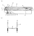
- Fig. 3 is a schematic front view showing the configuration of a locking member, used in the present invention.
- Fig. 4 is a sectional view showing a state where the media cassette, according to the present invention, is mounted into the media dispenser;
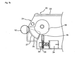
- Fig. 5a is a sectional view showing a state where a door of the media cassette is closed, according to the present invention.
- Fig. 5b is a sectional view showing a state where the door of the media cassette is open, according to the present invention.
- Fig. 2 is a sectional view schematically showing the configuration of the media cassette for the media dispenser, according to an embodiment of the present invention
- Fig. 3 is a front view schematically showing the configuration of a locking member, used in the present invention
- Fig. 4 is a sectional view schematically showing a state where the media cassette is mounted into the media dispenser.
- a media cassette 20 is mounted into a media dispenser 40.
- the media cassette 20 is filled with a large amount of media m , in order to provide the media m sheet by sheet
- An external appearance of the media cassette 20 is defined by a cassette body 22.
- the cassette body 22 is shaped as a rectangular parallelepiped.
- a storage space 23, with media filled therein, is provided within the cassette body 22.
- a discharging opening 24 is provided at a front side of the cassette body 22.
- the discharging opening 24 is a portion through which the media in the cassette body 22 are discharged to a feeding line or path of the media dispenser 40.
- a width of the discharging opening 24 is formed to be greater than a width of the media m .
- An inclined guide 25 for allowing the media m to be securely seated and guided toward the discharging opening 24 is provided at a position adjacent to the discharging opening 24 within the cassette body 22.
- the media m are guided by the inclined guide 25 in a state where at least lateral ends thereof are in contact with the inclined guide 25.
- the inclined guide 25 is formed at a position(s) corresponding to the lateral ends of the media m within the cassette body 22.
- the discharging opening 24 is selectively opened and closed by a door 26.
- the door 26 is configured either to open the discharging opening 24 when the media cassette 20 is mounted into the media dispenser 40 or to close the discharging opening 24 when the media cassette is not mounted into the media dispenser. That is, the door 26 is installed such that both ends thereof can be pivoted on a central shaft 26' within the cassette body 22.
- the gear 52 is formed on a front surface of the door 26.
- the door 26 should be formed to have a width greater than the width of the media m .
- a catching step 28 is formed at a side of the door 26.
- a locking portion 36' of a locking member 36 engages the catching step 28 such that the door 26 causes the discharging opening 24 to be kept closed.
- the catching step 28 is formed at one or both sides of the door 28 within the storage space 23.
- a push plate 30 is installed within the cassette body 22.
- the push plate 30 serves to push the media m toward the inclined guide 25 within the storage space 23.
- the push plate 30 is formed such that a front surface thereof includes an inclined surface 32 having the same inclination as the inclined guide 25.
- the push plate 30 is configured to push the media m toward the discharging opening 24 within the storage space 23 using a pushing force supplied by a driving force generated from a spring or an additional driving source.
- the driving force generated from the an additional driving source is used as the pushing force.
- a solenoid 34 serving as a driving source, is installed within the cassette body 22.
- the solenoid 34 receives an electrical signal when the media cassette 20 is mounted into the media dispenser 40.
- the signal drives the solenoid 34.
- the solenoid 34 includes a plunger 34' which is driven to move toward and away from the solenoid 34. In this embodiment, the plunger 34' retracts toward the solenoid 34 when it is driven.
- a slide guide 35 is connected to the plunger 34' of the solenoid 34.
- the slide guide 35 is formed with an inclined portion 35' for actuating the locking member 36.
- the locking member 36 is lifted or lowered as the solenoid 34 is driven. As shown in Fig. 3 , the locking member 36 is generally formed to have a U shape. The locking portions 36' are formed at opposite upper ends of the locking member 36 to selectively engage the catching step 28 of the door 26. For reference, the locking member 36 should be designed such that a distance between the locking portions 36' is greater than the width of the media m discharged through the discharging opening 24 so that the locking portions 36' do not interfere with the traveling media m .
- the locking member 36 is formed with another inclined portion 37 cooperating with the inclined portion 35' of the slide guide 35.
- the inclined portion 37 is formed to be inclined upward toward a rear end of the media cassette 20 as viewed from a front end of the media cassette 20.
- the locking member 36 is guided to be lifted or lowered by means of a lifting guide 38 that is provided in the cassette body 22.
- the locking member 36 is supported at opposite sides thereof by means of springs 39.
- the springs 39 exert an elastic force on the locking member 36 in a direction in which the locking portions 36' of the locking member 36 engage the catching step 28 of the door 26.
- the springs 39 are installed within the lifting guide 38 so as to exert the elastic force on the locking member 36.
- a driving motor 42 and a feed roller 44, driven by the driving motor 42, are installed at a side of the media dispenser 40.
- the feed roller 44 is rotated by receiving power from the driving motor 42, but a mechanism for transmitting the power to the feed roller is omitted in the figures to simplify the illustration.
- the power transmission between the driving motor 42 and the feed roller 44 may be accomplished by using a gear or belt.
- a contra-roller 46 is also installed to pair up with the feed roller 44.
- the feed roller 44 and the contra-roller 46 are rotated in opposite directions and separate any two stacked sheets of media m from each other when the sheets of media pass between the paired rollers 44 and 46.
- the power can be transmitted between the feed roller 44 and the contra-roller 46 by connecting them with each other using a gear or belt
- a pickup roller 48 is provided such that it is connected with the feed roller 44 through a driving belt 47 or equivalent gears to receive power.
- the pickup roller 48 is provided at a tip end of a separate link (not shown in the figures).
- the link is pivoted on a rotational center shaft of the feed roller 44, and the pickup roller 48 is installed adjacent the freely rotating end of the link.
- the pickup roller 48 is inserted slightly into the cassette body 22 through the discharging opening 24 such that a side surface thereof is placed at a position corresponding or in line with the inclined guide 25.
- the pickup roller 48 is installed such that both ends of its rotational center shaft 48' are supported on the end of the link. That is, a pair of links are provided to support both ends of the rotational center shaft 48'.
- a pressure roller 50 is installed on the shaft 48'. The pressure roller 50 is preferably installed such that it is not rotated about the shaft 48'.
- the opening/closing gear 52 is installed at a position corresponding to the door 26 of the media cassette 20 within the media dispenser 40.
- the opening/closing gear 52 can be rotated by receiving power from an additional driving source separate from the driving motor 42.
- the opening/closing gear 52 is engaged with the gear unit 27 of the door 26 to open and close the door 26.
- the media cassette 20 is detachably mounted internally in the media dispenser 40.
- the media cassette 20, with the media m filled in the storage space 23, is inserted into the media dispenser 40.
- the door 26 of the media cassette 20 covers the discharging opening 24.
- the door 26 cannot be opened because the locking portions 36' of the locking member 36, that moved upward by means of the elastic force of the springs 39, are engaging the catching step 28. That is, the door 26 is in a state where it cannot be rotated about the central shaft 26'.
- the locking member 36 moves downward along the lifting guide 38 against the elastic force of the springs 39. This downward movement is performed through the cooperation between the inclined portion 35' of the slide guide 35 and the inclined portion 37 of the locking member 36.
- the locking portions 36' of the locking member 36 are moved out from the catching step 28 of the door 26 and the door 26 is then unlocked.
- a state where the locking portions 36' were moved out form the catching step 28 is shown in Fig. 5b .
- the opening/closing gear 52 is driven by means of the additional driving source. If the opening/closing gear 52 is driven, power is transmitted to the door 26 through the gear unit 27 engaged with the opening/closing gear 52, and the door 26 is pivoted on the central shaft 26' to open the discharging opening 24. Such a state is shown in Fig. 5b . After, or as, the door 26 is opened, power to the solenoid 34 can be removed.
- the plunger 34 does not pull the slide guide 35 any longer and the locking member 36 is thus lifted by means of a restoring force of the springs 39. Therefore, the locking portions 36' of the locking member 36 engage or snap into the catching step 28 of the door 26 as the door 26 moves to the fully closed position. Accordingly, the door 26 is locked in a state where the discharging opening 24 is closed, as shown in Fig. 5a .
- an operator may detach the media cassette 20 from the media dispenser 40. Once the media cassette 20 is removed, the door 20 is locked and unless the door 20 or cassette body 22 is broken or destroyed, the media m in the storage space 23 defined in the cassette body 22 cannot be taken out
- the door of the media cassette cannot be opened unless the solenoid is operated. Since the media cassette can only be opened at a place where an electrical signal for operating the solenoid can be input, it reduces the chance that the media are stolen or lost while the media cassette is carried.
- the power can be input to the solenoid by attaching a jack on the outside of the media cassette 20, which receives power from a plug attached to the media dispenser 1, when the media cassette 20 is inserted into the media dispenser 1, or into a plug at the bank where the media cassette 20 is opened to fill/remove media therein.
- the driving force of the solenoid may be transmitted to the locking member in various manners.
- the driving force of the solenoid may be transmitted to the locking member via a link mechanism or belt.
- another driving source may be used instead of a solenoid. That is, any kind of driving source may be employed in the present invention if it can be properly turned on and off.
Landscapes
- Engineering & Computer Science (AREA)
- Mechanical Engineering (AREA)
- Physics & Mathematics (AREA)
- General Physics & Mathematics (AREA)
- Sheets, Magazines, And Separation Thereof (AREA)
- Feeding And Guiding Record Carriers (AREA)
- Automatic Disk Changers (AREA)
Claims (15)
- Medienkassette für eine Medienausgabevorrichtung, mit:einem Kassettenkörper (22) mit einem Speicherraum (23), in den Medien eingefüllt sind, und einer Ausgabeöffnung (24), über die die Medien ausgegeben werden;einer Tür (26) zum selektiven Öffnen und Schließen der Ausgabeöffnung (24); undeinem Türschließmechanismus zum selektiven Verriegeln und Entriegeln der Tür (26) in Antwort auf ein externes elektrisches Signal,wobei der Türschließmechanismus aufweist:eine im Kassettenkörper installierte Antriebsquelle; undein im Kassettenkörper (22) installiertes Verriegelungselement (36);dadurch gekennzeichnet, dass das Verriegelungselement (36) dazu geeignet ist, in Antwort auf eine Antriebskraft der Antriebsquelle mit einem Abschnitt der Tür (26) selektiv in oder außer Eingriff zu kommen.
- Medienkassette nach Anspruch 1, wobei die Ausgabeöffnung (24) an einer Seite des Kassettenkörpers (22) angeordnet ist.
- Medienkassette nach Anspruch 1 oder 2, wobei der Türschließmechanismus benachbart zum Speicherraum (23) im Kassettenkörper (22) installiert ist.
- Medienkassette nach Anspruch 1, 2 oder 3, wobei eine Getriebeeinheit (27) an einer Außenfläche der Tür (26) befestigt oder darauf integral ausgebildet ist, wobei die Getriebeeinheit (27) dazu geeignet ist, mit einem angetriebenen Öffnungs-/Schließzahnrad (52) der Medienausgabevorrichtung (40) in Eingriff zu kommen, um die Tür (26) zu öffnen und zu schließen, wenn die Medienkassette (20) in der Medienausgabevorrichtung (40) montiert ist.
- Medienkassette nach einem der Ansprüche 1 bis 4, wobei die Tür (26) ein erstes und ein zweites Ende aufweist, die mit dem Kassettenkörper (22) schwenkbar verbunden sind.
- Medienkassette nach Anspruch 1, wobei die Antriebsquelle ein Solenoid (34) ist.
- Medienkassette nach Anspruch 6, wobei der Solenoid (34) das Verriegelungselement (36) bewegt, um es mit dem Abschnitt der Tür außer Eingriff zu bringen, wenn dem Solenoid Leistung zugeführt wird.
- Medienkassette nach Anspruch 7, wobei die dem Solenoid (34) zugeführte Leistung von einer außerhalb des Kassettenkörpers (22) angeordneten Leistungsquelle zugeführt wird.
- Medienkassette nach Anspruch 8, wobei durch das Außereingriffbringen des Verriegelungselements mit dem Abschnitt der Tür (26) die Tür (26) entriegelt wird, so dass die Tür (26) geöffnet werden kann.
- Medienkassette nach Anspruch 1, wobei das Verriegelungselement (36) durch ein elastisches Element gehalten wird, und wobei das Verriegelungselement durch das elastische Element tendenziell in eine Richtung bewegt wird, in der veranlasst wird, dass das Verriegelungselement die Tür zum Schließen verriegelt.
- Medienkassette nach Anspruch 10, wobei eine Gleitführung (35) zwischen der Antriebsquelle und dem Verriegelungselement (36) angeordnet ist, und wobei die Gleitführung (35) in Antwort auf die Antriebkraft der Antriebsquelle eine Anhebe- oder Absenkbewegung des Verriegelungselements (36) veranlasst.
- Medienkassette nach Anspruch 11, wobei an Kontaktoberflächen der Gleitführung (35) bzw. des Verriegelungselements (36) schräge Abschnitte ausgebildet sind, die dazu geeignet sind, miteinander in Eingriff zu kommen, um die Anhebe- und Absenkbewegung des Verriegelungselements (36) zu bewirken.
- Medienkassette nach Anspruch 10, wobei das Verriegelungselement (36) Verriegelungsabschnitte aufweist, die in einem vorgegebenen Intervall voneinander beabstandet sind und sich an gegenüberliegenden Enden des Verriegelungselements im Wesentlichen parallel zueinander erstrecken, so dass das Verriegelungselement (36) im Wesentlichen U-förmig ausgebildet ist.
- Medienkassette nach Anspruch 13, wobei das vorgegebene Intervall größer ist als die Breite der im Speicherraum des Kassettenkörpers (22) stapelförmig anzuordnenden Medien.
- Medienausgabevorrichtung mit:einer Medienkassette (20) nach einem der Ansprüche 1 bis 14, ferner mit:einem Zuführmodul mit einer Aufnahmewalze zum plattenweisen Entnehmen von Medien vom Speicherraum des Kassettenkörpers; undeinem Ausgabemodul zum Empfangen von Medienplatten vom Zuführmodul und zum Ausgeben der Medienplatten an einen Kunden.
Applications Claiming Priority (2)
| Application Number | Priority Date | Filing Date | Title |
|---|---|---|---|
| KR1020030097663A KR100578339B1 (ko) | 2003-12-26 | 2003-12-26 | 매체자동지급기용 매체카세트 |
| KR2003097663 | 2003-12-26 |
Publications (2)
| Publication Number | Publication Date |
|---|---|
| EP1548660A1 EP1548660A1 (de) | 2005-06-29 |
| EP1548660B1 true EP1548660B1 (de) | 2008-08-20 |
Family
ID=34545914
Family Applications (1)
| Application Number | Title | Priority Date | Filing Date |
|---|---|---|---|
| EP04029456A Expired - Lifetime EP1548660B1 (de) | 2003-12-26 | 2004-12-13 | Kassette für Medien für ein Medienausgabegerät |
Country Status (5)
| Country | Link |
|---|---|
| US (1) | US7520501B2 (de) |
| EP (1) | EP1548660B1 (de) |
| KR (1) | KR100578339B1 (de) |
| CN (1) | CN1331717C (de) |
| DE (1) | DE602004015924D1 (de) |
Families Citing this family (13)
| Publication number | Priority date | Publication date | Assignee | Title |
|---|---|---|---|---|
| KR100527169B1 (ko) * | 2003-12-31 | 2005-11-09 | 엘지엔시스(주) | 매체자동지급기의 매체카세트 개폐장치 |
| KR100673040B1 (ko) * | 2005-09-16 | 2007-01-24 | 엘지엔시스(주) | 매체자동지급기의 매체 가이드장치 |
| JP2007264964A (ja) * | 2006-03-28 | 2007-10-11 | Fujitsu Ltd | 筐体のロック機構を備えた装置 |
| KR101122478B1 (ko) * | 2010-02-26 | 2012-02-29 | 노틸러스효성 주식회사 | 금융자동화기기의 카세트 |
| US8479910B2 (en) * | 2010-08-26 | 2013-07-09 | Ncr Corporation | Removable media container |
| US8317187B2 (en) * | 2010-10-06 | 2012-11-27 | Seiko Epson Corporation | Recording apparatus |
| US8479979B2 (en) * | 2010-11-29 | 2013-07-09 | Ncr Corporation | Media cassette |
| US8496242B2 (en) * | 2010-11-29 | 2013-07-30 | Ncr Corporation | Media cassette |
| CN103347420B (zh) * | 2010-12-03 | 2016-06-01 | 因特梅特罗工业公司 | 具有锁定机构的存储装置 |
| KR101186433B1 (ko) | 2011-03-14 | 2012-09-27 | 엘지엔시스(주) | 셔터 개폐장치 및 이를 이용한 금융기기 |
| EP2750112A1 (de) * | 2012-12-27 | 2014-07-02 | Wincor Nixdorf International GmbH | Geldkassette und Vorrichtung zur Handhabung von Wertscheinen mit mechanischer Kodierung |
| CN103971448B (zh) * | 2013-02-04 | 2016-08-24 | 山东新北洋信息技术股份有限公司 | 钱箱及具有该钱箱的识币装置 |
| CN112854910B (zh) * | 2020-12-25 | 2022-05-24 | 上海海蛟交通设备有限公司 | 钞箱及其可锁盖体 |
Family Cites Families (7)
| Publication number | Priority date | Publication date | Assignee | Title |
|---|---|---|---|---|
| GB8404364D0 (en) * | 1984-02-20 | 1984-03-28 | De La Rue Syst | Sheet dispensing apparatus |
| CA1310502C (en) * | 1986-10-08 | 1992-11-24 | De La Rue Systems Limited | Sheet store |
| DE3706829A1 (de) * | 1987-03-03 | 1988-09-15 | Nixdorf Computer Ag | Ausgabeeinheit fuer wertscheine |
| JP3889826B2 (ja) | 1995-12-28 | 2007-03-07 | 日本金銭機械株式会社 | 紙幣鑑別装置 |
| GB9603999D0 (en) | 1996-02-26 | 1996-04-24 | De La Rue Systems Ltd | Sheet tranport apparatus and sheet store |
| CA2360017C (en) * | 2000-11-01 | 2005-11-22 | Lg Electronics Inc. | Media dispenser |
| US6820872B2 (en) * | 2001-09-12 | 2004-11-23 | Lg N-Sys Inc. | Media cassette and media dispensing machine having the same |
-
2003
- 2003-12-26 KR KR1020030097663A patent/KR100578339B1/ko not_active Expired - Fee Related
-
2004
- 2004-11-30 US US10/998,719 patent/US7520501B2/en not_active Expired - Lifetime
- 2004-12-13 EP EP04029456A patent/EP1548660B1/de not_active Expired - Lifetime
- 2004-12-13 DE DE602004015924T patent/DE602004015924D1/de not_active Expired - Lifetime
- 2004-12-24 CN CNB2004101049990A patent/CN1331717C/zh not_active Expired - Fee Related
Also Published As
| Publication number | Publication date |
|---|---|
| US7520501B2 (en) | 2009-04-21 |
| KR20050066382A (ko) | 2005-06-30 |
| DE602004015924D1 (de) | 2008-10-02 |
| CN1331717C (zh) | 2007-08-15 |
| US20050140079A1 (en) | 2005-06-30 |
| KR100578339B1 (ko) | 2006-05-11 |
| CN1648022A (zh) | 2005-08-03 |
| EP1548660A1 (de) | 2005-06-29 |
Similar Documents
| Publication | Publication Date | Title |
|---|---|---|
| EP1548660B1 (de) | Kassette für Medien für ein Medienausgabegerät | |
| KR19980080124A (ko) | 카드분배카세트 | |
| EP1550625B1 (de) | Medienausgabegerät umfassend eine Medienkassette mit innerem Schloss | |
| EP2600322A1 (de) | Mediumsaufbewahrungsbox | |
| KR101079965B1 (ko) | 매체카세트의 록킹장치 | |
| JP3855573B2 (ja) | 自動販売機の商品搬出装置 | |
| KR101171460B1 (ko) | 지폐저장박스의 푸쉬플레이트 승강 구조 | |
| KR101046821B1 (ko) | 카세트의 푸쉬플레이트 잠금장치 | |
| KR100926856B1 (ko) | 금융자동화기기용 회수함 구조 | |
| EP3509043B1 (de) | Selbstverriegelndes bargelddepotsystem und geldkassette dafür | |
| KR101035189B1 (ko) | 금융자동화기기의 카세트 | |
| US11315391B2 (en) | Automatic teller machine having a note storage unit with a door capable of being locked and unlocked | |
| KR100802287B1 (ko) | 지폐저장박스의 커넥터 덮개구조 | |
| KR101122478B1 (ko) | 금융자동화기기의 카세트 | |
| CN1573821B (zh) | 纸币识别装置 | |
| KR101072163B1 (ko) | 매체카세트박스의 해제장치 | |
| KR101077293B1 (ko) | 금융자동화기기의 매체저장장치 | |
| CN221485939U (zh) | 一种钞箱及现金循环处理设备 | |
| KR102530442B1 (ko) | 슬림형 카드 디스펜서 | |
| KR100642242B1 (ko) | 지폐도난방지기능을 갖는 지폐방출장치 | |
| JP2669745B2 (ja) | 紙葉類取扱機 | |
| KR100926857B1 (ko) | 금융자동화기기용 회수함 구조 | |
| US20250308310A1 (en) | Cassette for automated teller machine | |
| JP5228814B2 (ja) | 紙幣識別装置 | |
| KR100552227B1 (ko) | 장착 및 탈착시 부하가 회피되는 리싸이클박스의 구동장치 |
Legal Events
| Date | Code | Title | Description |
|---|---|---|---|
| PUAI | Public reference made under article 153(3) epc to a published international application that has entered the european phase |
Free format text: ORIGINAL CODE: 0009012 |
|
| 17P | Request for examination filed |
Effective date: 20050113 |
|
| AK | Designated contracting states |
Kind code of ref document: A1 Designated state(s): AT BE BG CH CY CZ DE DK EE ES FI FR GB GR HU IE IS IT LI LT LU MC NL PL PT RO SE SI SK TR |
|
| AX | Request for extension of the european patent |
Extension state: AL BA HR LV MK YU |
|
| AKX | Designation fees paid |
Designated state(s): DE FR GB IT |
|
| 17Q | First examination report despatched |
Effective date: 20070605 |
|
| GRAP | Despatch of communication of intention to grant a patent |
Free format text: ORIGINAL CODE: EPIDOSNIGR1 |
|
| GRAS | Grant fee paid |
Free format text: ORIGINAL CODE: EPIDOSNIGR3 |
|
| GRAA | (expected) grant |
Free format text: ORIGINAL CODE: 0009210 |
|
| AK | Designated contracting states |
Kind code of ref document: B1 Designated state(s): DE FR GB IT |
|
| REG | Reference to a national code |
Ref country code: GB Ref legal event code: FG4D |
|
| REF | Corresponds to: |
Ref document number: 602004015924 Country of ref document: DE Date of ref document: 20081002 Kind code of ref document: P |
|
| PLBE | No opposition filed within time limit |
Free format text: ORIGINAL CODE: 0009261 |
|
| STAA | Information on the status of an ep patent application or granted ep patent |
Free format text: STATUS: NO OPPOSITION FILED WITHIN TIME LIMIT |
|
| 26N | No opposition filed |
Effective date: 20090525 |
|
| REG | Reference to a national code |
Ref country code: FR Ref legal event code: TP Owner name: LG CNS CO., LTD., KR Effective date: 20130729 |
|
| REG | Reference to a national code |
Ref country code: GB Ref legal event code: 732E Free format text: REGISTERED BETWEEN 20130822 AND 20130828 |
|
| REG | Reference to a national code |
Ref country code: DE Ref legal event code: R082 Ref document number: 602004015924 Country of ref document: DE Representative=s name: VOSSIUS & PARTNER, DE |
|
| REG | Reference to a national code |
Ref country code: DE Ref legal event code: R082 Ref document number: 602004015924 Country of ref document: DE Representative=s name: VOSSIUS & PARTNER, DE Effective date: 20130923 Ref country code: DE Ref legal event code: R081 Ref document number: 602004015924 Country of ref document: DE Owner name: LG CNS CO., LTD., KR Free format text: FORMER OWNER: LG N-SYS. INC., SEOUL, KR Effective date: 20130923 Ref country code: DE Ref legal event code: R082 Ref document number: 602004015924 Country of ref document: DE Representative=s name: VOSSIUS & PARTNER PATENTANWAELTE RECHTSANWAELT, DE Effective date: 20130923 |
|
| REG | Reference to a national code |
Ref country code: FR Ref legal event code: PLFP Year of fee payment: 12 |
|
| REG | Reference to a national code |
Ref country code: FR Ref legal event code: PLFP Year of fee payment: 13 |
|
| REG | Reference to a national code |
Ref country code: FR Ref legal event code: PLFP Year of fee payment: 14 |
|
| REG | Reference to a national code |
Ref country code: DE Ref legal event code: R082 Ref document number: 602004015924 Country of ref document: DE Representative=s name: VOSSIUS & PARTNER PATENTANWAELTE RECHTSANWAELT, DE Ref country code: DE Ref legal event code: R081 Ref document number: 602004015924 Country of ref document: DE Owner name: ATEC AP CO., LTD., SEONGNAM-SI, KR Free format text: FORMER OWNER: LG CNS CO., LTD., SEOUL, KR |
|
| REG | Reference to a national code |
Ref country code: GB Ref legal event code: 732E Free format text: REGISTERED BETWEEN 20181220 AND 20181224 |
|
| PGFP | Annual fee paid to national office [announced via postgrant information from national office to epo] |
Ref country code: GB Payment date: 20201209 Year of fee payment: 17 Ref country code: FR Payment date: 20201209 Year of fee payment: 17 |
|
| GBPC | Gb: european patent ceased through non-payment of renewal fee |
Effective date: 20211213 |
|
| PG25 | Lapsed in a contracting state [announced via postgrant information from national office to epo] |
Ref country code: GB Free format text: LAPSE BECAUSE OF NON-PAYMENT OF DUE FEES Effective date: 20211213 |
|
| PG25 | Lapsed in a contracting state [announced via postgrant information from national office to epo] |
Ref country code: FR Free format text: LAPSE BECAUSE OF NON-PAYMENT OF DUE FEES Effective date: 20211231 |
|
| PGFP | Annual fee paid to national office [announced via postgrant information from national office to epo] |
Ref country code: IT Payment date: 20221206 Year of fee payment: 19 Ref country code: DE Payment date: 20221205 Year of fee payment: 19 |
|
| REG | Reference to a national code |
Ref country code: DE Ref legal event code: R119 Ref document number: 602004015924 Country of ref document: DE |
|
| PG25 | Lapsed in a contracting state [announced via postgrant information from national office to epo] |
Ref country code: DE Free format text: LAPSE BECAUSE OF NON-PAYMENT OF DUE FEES Effective date: 20240702 |
|
| PG25 | Lapsed in a contracting state [announced via postgrant information from national office to epo] |
Ref country code: DE Free format text: LAPSE BECAUSE OF NON-PAYMENT OF DUE FEES Effective date: 20240702 |
|
| PG25 | Lapsed in a contracting state [announced via postgrant information from national office to epo] |
Ref country code: IT Free format text: LAPSE BECAUSE OF NON-PAYMENT OF DUE FEES Effective date: 20231213 |