EP1548874A1 - Blitzschutz für Antennenanlagen - Google Patents
Blitzschutz für Antennenanlagen Download PDFInfo
- Publication number
- EP1548874A1 EP1548874A1 EP04016127A EP04016127A EP1548874A1 EP 1548874 A1 EP1548874 A1 EP 1548874A1 EP 04016127 A EP04016127 A EP 04016127A EP 04016127 A EP04016127 A EP 04016127A EP 1548874 A1 EP1548874 A1 EP 1548874A1
- Authority
- EP
- European Patent Office
- Prior art keywords
- lightning
- lightning protection
- protection according
- helical
- radiator
- Prior art date
- Legal status (The legal status is an assumption and is not a legal conclusion. Google has not performed a legal analysis and makes no representation as to the accuracy of the status listed.)
- Granted
Links
Images


Classifications
-
- H—ELECTRICITY
- H01—ELECTRIC ELEMENTS
- H01Q—ANTENNAS, i.e. RADIO AERIALS
- H01Q1/00—Details of, or arrangements associated with, antennas
- H01Q1/50—Structural association of antennas with earthing switches, lead-in devices or lightning protectors
Definitions
- the invention relates to a lightning protection for antenna systems according to the preamble of claim 1.
- radiator and radiator structures surrounding cylindrical Housed protective housing.
- These are a permeable to electromagnetic radiation Housing, which usually consists of one with glass fibers reinforced plastic (GRP) is formed.
- GRP glass fibers reinforced plastic
- Typical dimensions of such cylinders for broadcast transmitters be a diameter of 0.3 m to 4 m and more.
- the height of such cylindrical protective housing may well have values of 20 m to 30 m.
- the lightning protection consists of a lightning catcher at the upper end of the cylindrical protective housing.
- lightning rods or general Lightning arrestors offset in the circumferential direction arranged, e.g. in the form of straight line ends, those with radially and vertically upwards Project component outwards and end freely.
- lightning baskets where respectively two diametrically opposed and outward extending, in itself free ends of metallic rods via a semicircular electrical connection line or metal rod connected together, resulting in a basket-like design results.
- Lightning conductors can be the lightning current from the lightning catcher on Mass are derived. At the same time are such Lightning rod also suitable, the entire antenna arrangement to protect against lateral impacts.
- the antenna system includes transmitting antennas with horizontally polarized radiators (for example horizontally polarized dipole radiators or slot radiators etc.), so the influence of the lightning conductor in general due to the polarization decoupling very low.
- horizontally polarized radiators for example horizontally polarized dipole radiators or slot radiators etc.
- the radiation pattern becomes vertical polarized transmitting antenna by a lightning rod strongly influenced. This applies in principle even if alternatively and additionally receiving antennas are provided.
- a clear improvement in the radiation characteristics in particular for vertically polarized antennas and transmitting antennas can be realized by the fact that the lightning rods or the lightning arrester structure is designed such that the lightning conductor lines preferably along a Spiral run from top to bottom and the antenna with the radiators and radiator structures therein surround. At least two are preferably offset by 180 ° provided to each other lying coil, which are preferred are mounted on the GRP cylinder.
- the lightning arrester devices serve simultaneously as lightning devices.
- a lightning arrester structure formed in this way can be of Home also used with spotlights or spotlights be, for example, in horizontal polarization send or receive.
- one such lightning rod structure benefits even then if the transmitter initially only emitters or radiator structures should include with horizontal polarization. Because even with a subsequent retrofitting of the antenna system with vertical radiators or radiator structures this has the advantage that the lightning rod structure can be left unchanged, since when using the Lightning arrester structure according to the invention optionally retrofitted vertically polarized antenna elements in terms of their electrical characteristic Transmitting and receiving properties are not adversely affected become.
- the slope of the helix or helical at a distance to Antenna around these lightning arrester structures can with respect to the slope and / or the number of Spirals vary greatly.
- the training is preferred such that at least each vertical strip on the in usually provided cylindrical protective enclosure the antenna mast system at least once from the helix, helical or diagonal lightning conductor structure or lightning rod line is crossed.
- the pitch of the helical structure in vary widely and for example preferred more than 20 ° and less than 87 °. Preferred are Angular ranges between 40 ° to 70 °.
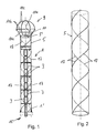
- Figure 1 is a schematic side view of an antenna system shown with a lightning protection device.
- the antenna system includes a vertically oriented supporting structure 1, on which in the vertical direction one above the other and circumferentially offset one Variety of radiators 3 and 3 radiator structures for Transmission and / or reception are arranged.
- Such Antenna system can, for example, as a television and / or Broadcast antenna system serve, for example, in the so-called Band III operates (174 MHz to 230 MHz) and / or for example in band IV and V (470 MHz to 860 MHz). Additionally or alternatively, the transmitter in the FM area send and receive, so for example in the 88th to 108 MHz range.
- the entire supporting structure 1 with the spotlights and Radiator structures 3 is in the illustrated embodiment arranged in a cylindrical protective housing 5 and thus protected against environmental influences. It is about while a permeable to electromagnetic radiation Protective housing, usually a GRP housing.
- the bearing Structure 1 can essentially by the cylindrical protective housing 5 may be formed, which in Vertical distance includes crossbars inside. At the Protective cladding can then project prominently inside Be attached spotlights and radiator structures. alternative or in addition, but can also inside the protective cover 5 mast-shaped belonging to the support structure facilities be provided, for example, steel beams, to which then the spotlights and radiator structures like but also the protective covering in addition to attached or connected with it.
- Lightning catcher 9 In the upper front end 5 'of the protective housing is a so-called Lightning catcher 9 is provided. This includes one conductive, placed on the front end 5 'of the protective housing 5 End cover 11, on which in the circumferential direction offset lying with vertical and horizontal Component radially outwardly projecting lightning rods 11a are arranged, which via one or more connecting them annular lines 11b electrically conductive connected, which also provides a mechanical support the lightning rods 11a is ensured. Preferred are two diagonally opposite ends of the mentioned Lightning rods 11a by means of convexly upwardly projecting connected semicircular line sections 11c, whereby one formed in the manner of an inverted basket Structure yields, which is why this arrangement also Lightning catcher is called.
- FIG. 1 and 2 are on the outer circumference of the protective housing 5 with the lightning catcher 9 a ground potential 15 at the antenna 1 'connecting Lightning derivatives 17 provided.
- These lightning conductors 17 exist in the embodiment of Figure 1 of two offset by 180 ° to each other lying helical or helical Lightning derivatives 17, in the embodiment shown according to Figure 1, the cylindrical protective housing 5, for example, at least once from the top to run around below.
- FIG. 2 is a perspective view of this Lightning conductor structure without antenna mast and spotlight or Radiator structures and reproduced without lightning 9.
- Figure 3 is the side view of the cylindrical Protective housing 5 reproduced in unwound representation.
- the individual lightning conductors include a pitch angle ⁇ with respect to the horizontal.
- the slopes of the individual lightning conductors can be quite on the order of a few Meters are.
- the pitch angle ⁇ may therefore be preferred Values between 20 ° to 87 ° from the horizontal in particular values between preferably 40 ° up to 70 °.
- a einlnlige lightning rod structure to get voted. It should be based on the Total height of the protective housing the arrangement be such that the at least one spiral formation of the derivative 17 over the entire length of the protective housing 5 the Antenna mast with the radiator and radiator structures at least once revolves, preferably several times.
- helix or the helix 17 left or right around are formed running, can be chosen arbitrarily.
- the lightning discharge for example clockwise, preferably on the protective housing. 5 is arranged circumferentially and then at a certain height in an opposite helical or spiral structure passes. If such a change occurs more frequently, it may be from a Zigzag structure are spoken, as for example is explained with reference to Figure 6 and 7.
- the Lightning arrester but also from top to bottom sinusoidal be designed to run. Also mixed forms between a sinusoidal and a zigzag structure are conceivable.
- the lightning conductors have a double function. They serve for a lightning discharge and on the other hand, a protection against lateral impacts Offer. They are therefore also common in the literature referred to as a catch ladder.
- Figure 7 or for example with sinusoidal or rather sinusoidal lightning discharges are generally preferred not just two, but three or four such derivatives be provided. Due to the appropriate design increases the protection range. The smallest distance between two adjacent capture lines should be there preferably less than 4 m.
Landscapes
- Details Of Aerials (AREA)
- Elimination Of Static Electricity (AREA)
- Emergency Protection Circuit Devices (AREA)
Abstract
Description
- Figur 1:
- eine schematische Seitenansicht einer Antennenanlage mit einem Antennenmast und einem zylinderförmigen GFK-Schutzgehäuse mit oben angeordnetem Blitzfangkorb und zwei helixförmigen Blitzableitungen;
- Figur 2:
- eine perspektivische Darstellung der Blitzableiter-Strukturen in dreidimensionaler Wiedergabe mit zwei wendelförmigen Blitzableitern;
- Figur 3:
- eine Abwicklung des in Figur 1 und 2 wiedergegebenen zylinderförmigen Schutzmantels lediglich in einer Teilhöhe mit den darauf befindlichen Blitzableitungen entsprechend dem Ausführungsbeispiel nach Figur 2;
- Figur 4:
- ein zu Figur 3 abgewandeltes Ausführungsbeispiel in abgewickelter Seitendarstellung im Falle von drei versetzt zueinander angeordneten helixförmigen Blitzableitungen;
- Figur 5:
- ein zu Figur 4 abgewandeltes Ausführungsbeispiel in abgewickelter Seitenansicht, bei welchem vier Ableitungen mit größerem Steigungswinkel verwendet werden;
- Figur 6:
- ein abgewandeltes Ausführungsbeispiel mit zickzackförmig von oben nach unten verlaufenden Blitzableitungen, wo jeweils benachbarte Blitzableitungen symmetrisch zueinander angeordnet sind; und
- Figur 7:
- ein zu Figur 6 abgewandeltes Ausführungsbeispiel in Seitenansicht bei abgewickelter Schutzumhüllung mit darauf verlaufenden Blitzableitungen, wobei die Blitzableitungen ebenfalls zickzackförmig vorgesehen sind, allerdings dabei gleich ausgerichtet sind (also in gleicher Höhenlage gleich ausgerichtet sind).
Claims (11)
- Blitzschutz für Antennenanlagen, mit mehreren in Vertikalrichtung versetzt liegenden Strahler und Strahleranordnungen (3), wobei vorzugsweise ein die Strahler oder Strahlerstrukturen (3') umgebendes, vorzugsweise zylinderförmiges Schutzgehäuse (5) aus für elektromagnetische Strahlen durchlässigem Material vorgesehen ist, und mit einer tragenden Struktur (1), die vorzugsweise ein Schutzgehäuse (5) oder eine vorzugsweise das Schutzgehäuse (5) umfassende mastförmige Antennentrageinrichtung aufweist, mit folgenden Merkmalen:gekennzeichnet durch die folgenden weiteren Merkmale:es ist eine Blitzschutzeinrichtung vorgesehen,die Blitzschutzeinrichtung umfasst von oben nach unten verlaufende Blitzableitungen (17), die vorzugsweise mit dem Schutzgehäuse (5) mechanisch verbunden sind,die zumindest eine von oben nach unten verlaufende Blitzableitung (17) ist von der Vertikalen abweichend so ausgerichtet, dass die Blitzableitung oder einzelne Abschnitte davon in Seitenbetrachtung winklig gegenüber der Vertikalrichtung ausgerichtet sind.
- Blitzschutz nach Anspruch 1, dadurch gekennzeichnet, dass zumindest eine helix-, wendel- oder schraubenförmig verlaufende Blitzableitung (17) vorgesehen ist.
- Blitzschutz nach Anspruch 1 oder 2, dadurch gekennzeichnet, dass zumindest zwei um 180° versetzt zueinander liegende helix-, wendel- oder schraubenförmige Blitzableitungen (17) vorgesehen sind.
- Blitzschutz nach Anspruch 1 oder 2, dadurch gekennzeichnet, dass die Blitzableitungen (17) in axialer Draufsicht spiralförmig ausgebildet sind und sich dabei über eine axiale Höhe erstrecken.
- Blitzschutz nach einem der Ansprüche 1 bis 4, dadurch gekennzeichnet, dass zumindest eine Blitzableitung (17) vorgesehen ist, die in Seitenbetrachtung von oben nach unten verlaufend von einer rechtsdrehenden in eine linksdrehende Helix-, Wendel- oder Schraubenstruktur oder umgekehrt übergeht.
- Blitzschutz nach Anspruch 5, dadurch gekennzeichnet, dass zumindest eine Blitzableitung (17) vorgesehen ist, die in Seitenansicht von oben nach unten zickzackförmig oder sinusförmig oder eine Mischform davon von oben nach unten hin und her verlaufend ausgebildet ist.
- Blitzschutz nach einem der Ansprüche 1 bis 6, dadurch gekennzeichnet, dass die zumindest eine Blitzableitung oder Abschnitte davon in einem Steigungswinkel α angeordnet sind, der größer als 20° und kleiner als 87° ist, vorzugsweise größer als 40° und kleiner als 70°.
- Blitzschutz nach einem der Ansprüche 1 bis 7, dadurch gekennzeichnet, dass dieser bei Antennenanlagen vorgesehen ist, die horizontal polarisierte Strahler und Strahlerstrukturen (3) umfassen.
- Blitzschutz nach einem der Ansprüche 1 bis 8, dadurch gekennzeichnet, dass dieser bei Antennenanlagen vorgesehen ist, die horizontal polarisierte Strahleranordnung, vertikal polarisierte Strahleranordnungen und/oder zirkular polarisierte Strahleranordnungen (3) umfassen.
- Blitzschutz nach einem der Ansprüche 1 bis 9, dadurch gekennzeichnet, dass die zickzack- und/oder sinusförmig oder in sonstiger Weise von oben nach unten hin und her verlaufende Blitzableitung (17) in Umgangsrichtung der Antennenanordnung zumindest zweifach, vorzugsweise dreioder vierfach versetzt zueinander angeordnet ist.
- Blitzschutz nach einem der Ansprüche 1 bis 10, dadurch gekennzeichnet, dass die Antennenanlage Strahler und Strahlerstrukturen umfasst, die insbesondere für den DVB-T-Betrieb vorgesehen sind.
Priority Applications (1)
| Application Number | Priority Date | Filing Date | Title |
|---|---|---|---|
| SI200430516T SI1548874T1 (sl) | 2003-12-23 | 2004-07-08 | Zascita pred strelo za antenske naprave |
Applications Claiming Priority (2)
| Application Number | Priority Date | Filing Date | Title |
|---|---|---|---|
| DE20319983U | 2003-12-23 | ||
| DE20319983U DE20319983U1 (de) | 2003-12-23 | 2003-12-23 | Blitzschutz für Antennenanlagen |
Publications (2)
| Publication Number | Publication Date |
|---|---|
| EP1548874A1 true EP1548874A1 (de) | 2005-06-29 |
| EP1548874B1 EP1548874B1 (de) | 2007-10-31 |
Family
ID=32892539
Family Applications (1)
| Application Number | Title | Priority Date | Filing Date |
|---|---|---|---|
| EP04016127A Expired - Lifetime EP1548874B1 (de) | 2003-12-23 | 2004-07-08 | Blitzschutz für Antennenanlagen |
Country Status (6)
| Country | Link |
|---|---|
| EP (1) | EP1548874B1 (de) |
| AT (1) | ATE377262T1 (de) |
| AU (1) | AU2004205190B2 (de) |
| DE (2) | DE20319983U1 (de) |
| ES (1) | ES2294401T3 (de) |
| SI (1) | SI1548874T1 (de) |
Cited By (2)
| Publication number | Priority date | Publication date | Assignee | Title |
|---|---|---|---|---|
| CN113898235A (zh) * | 2021-08-30 | 2022-01-07 | 张新磊 | 一种用于5g通信的网络通讯塔 |
| CN119381756A (zh) * | 2024-12-27 | 2025-01-28 | 湖南湘银河传感科技有限公司 | 防雷型gnss扼流圈天线 |
Families Citing this family (2)
| Publication number | Priority date | Publication date | Assignee | Title |
|---|---|---|---|---|
| DE102010053639B4 (de) * | 2010-12-07 | 2017-05-18 | Rohde & Schwarz Gmbh & Co. Kg | Blitzfangstab für Antennensysteme |
| CN113675579B (zh) * | 2021-08-31 | 2024-01-19 | 国网河南省电力公司经济技术研究院 | 一种安装5g天线的变电站构支架装置 |
Citations (5)
| Publication number | Priority date | Publication date | Assignee | Title |
|---|---|---|---|---|
| DE1297707B (de) * | 1962-06-29 | 1969-06-19 | Rohde & Schwarz | Antennenanordnung bestehend aus je einer Antenne fuer horizontal und vertikal polarisierte Abstrahlung |
| US4287520A (en) * | 1979-11-09 | 1981-09-01 | The United States Of America As Represented By The Secretary Of The Air Force | Slot chevron element for periodic antennas and radomes |
| DE19615213A1 (de) * | 1996-04-18 | 1997-10-23 | Deutsche Telekom Ag | Fernsteuerbare Miniaturhebebühne |
| WO1999056289A1 (en) * | 1998-04-24 | 1999-11-04 | Gasque, Marilyn, A. | Lightning retardant cable |
| JP2002016420A (ja) * | 2000-06-30 | 2002-01-18 | Mitsubishi Electric Corp | 誘雷装置及びその誘雷導体部の配置方法 |
Family Cites Families (6)
| Publication number | Priority date | Publication date | Assignee | Title |
|---|---|---|---|---|
| DE842664C (de) * | 1950-09-03 | 1952-06-30 | Siemens Ag | Blitzschutz fuer an geerdeten Traegern befestigte Strahler |
| US2985878A (en) * | 1952-02-13 | 1961-05-23 | Gen Electric | Wound antenna with conductive support |
| GB943779A (en) * | 1961-05-10 | 1963-12-04 | Siemens Ag | Improvements in aerials |
| JP2544440B2 (ja) * | 1988-04-30 | 1996-10-16 | 富士通株式会社 | 絶縁体成形の導波管を用いた避雷構造 |
| FR2634598B1 (fr) * | 1988-07-22 | 1990-10-05 | Thomson Lgt | Antenne omnidirectionnelle, notamment pour l'emission de signaux de radiodiffusion ou de television dans la bande des ondes decimetriques, et systeme rayonnant forme d'un groupement de ces antennes |
| US7068233B2 (en) * | 2002-05-06 | 2006-06-27 | Db Systems, Inc. | Integrated multipath limiting ground based antenna |
-
2003
- 2003-12-23 DE DE20319983U patent/DE20319983U1/de not_active Expired - Lifetime
-
2004
- 2004-07-08 AT AT04016127T patent/ATE377262T1/de not_active IP Right Cessation
- 2004-07-08 ES ES04016127T patent/ES2294401T3/es not_active Expired - Lifetime
- 2004-07-08 SI SI200430516T patent/SI1548874T1/sl unknown
- 2004-07-08 EP EP04016127A patent/EP1548874B1/de not_active Expired - Lifetime
- 2004-07-08 DE DE502004005354T patent/DE502004005354D1/de not_active Expired - Fee Related
- 2004-08-23 AU AU2004205190A patent/AU2004205190B2/en not_active Ceased
Patent Citations (5)
| Publication number | Priority date | Publication date | Assignee | Title |
|---|---|---|---|---|
| DE1297707B (de) * | 1962-06-29 | 1969-06-19 | Rohde & Schwarz | Antennenanordnung bestehend aus je einer Antenne fuer horizontal und vertikal polarisierte Abstrahlung |
| US4287520A (en) * | 1979-11-09 | 1981-09-01 | The United States Of America As Represented By The Secretary Of The Air Force | Slot chevron element for periodic antennas and radomes |
| DE19615213A1 (de) * | 1996-04-18 | 1997-10-23 | Deutsche Telekom Ag | Fernsteuerbare Miniaturhebebühne |
| WO1999056289A1 (en) * | 1998-04-24 | 1999-11-04 | Gasque, Marilyn, A. | Lightning retardant cable |
| JP2002016420A (ja) * | 2000-06-30 | 2002-01-18 | Mitsubishi Electric Corp | 誘雷装置及びその誘雷導体部の配置方法 |
Non-Patent Citations (1)
| Title |
|---|
| PATENT ABSTRACTS OF JAPAN vol. 2002, no. 05 3 May 2002 (2002-05-03) * |
Cited By (2)
| Publication number | Priority date | Publication date | Assignee | Title |
|---|---|---|---|---|
| CN113898235A (zh) * | 2021-08-30 | 2022-01-07 | 张新磊 | 一种用于5g通信的网络通讯塔 |
| CN119381756A (zh) * | 2024-12-27 | 2025-01-28 | 湖南湘银河传感科技有限公司 | 防雷型gnss扼流圈天线 |
Also Published As
| Publication number | Publication date |
|---|---|
| EP1548874B1 (de) | 2007-10-31 |
| DE20319983U1 (de) | 2004-08-19 |
| ATE377262T1 (de) | 2007-11-15 |
| DE502004005354D1 (de) | 2007-12-13 |
| ES2294401T3 (es) | 2008-04-01 |
| AU2004205190B2 (en) | 2009-03-05 |
| AU2004205190A1 (en) | 2005-07-07 |
| SI1548874T1 (sl) | 2008-02-29 |
Similar Documents
| Publication | Publication Date | Title |
|---|---|---|
| DE69812776T2 (de) | Wendelantenne mit variabler Länge | |
| DE69521935T2 (de) | Funkantennen | |
| AT393762B (de) | Als wendelantenne ausgebildete uhf-sendeund/oder empfangsantenne | |
| DE69309552T2 (de) | Antenne mit einstellbarer Neigung der Strahlungskeule | |
| DE19912465C2 (de) | Mehr-Bereichs-Antennenanlage | |
| EP1470615A1 (de) | Dualpolarisierte strahleranordnung | |
| DE112017008496B4 (de) | Antennenvorrichtung | |
| DE3118988A1 (de) | "antenne" | |
| DE102009037722A1 (de) | Antennenstab für eine Stabantenne für mehrere Funkdienste | |
| EP2346115B1 (de) | Antenne | |
| EP1548874A1 (de) | Blitzschutz für Antennenanlagen | |
| EP2047485B1 (de) | Vorrichtung zur elektrischen abschirmung einer hochspannungsdurchführung | |
| EP1134840B1 (de) | Antenne | |
| DE102012108600B3 (de) | Antennenanordnung mit flachbauendem Antennenelement | |
| DE202012103520U1 (de) | Kanalabdeckung | |
| EP0923859A1 (de) | Elektrischer Weidezaun | |
| EP1056155B1 (de) | Mobilantenne, insbesondere Fahrzeugantenne, für zumindest eine zirkulare und zumindest eine lineare, vorzugsweise vertikale Polarisation | |
| DE68920494T2 (de) | Breitband-Empfangsantenne. | |
| EP0271071B1 (de) | Einrichtung zur Überwachung von Masten einer Freileitung | |
| CH660261A5 (en) | EMP suppressor in a coaxial conductor | |
| DE3821529C2 (de) | ||
| EP1107357A1 (de) | Abstrahlendes koaxiales Hochfrequenz-Kabel | |
| DE1297707B (de) | Antennenanordnung bestehend aus je einer Antenne fuer horizontal und vertikal polarisierte Abstrahlung | |
| DE3822081C2 (de) | ||
| EP4498604A1 (de) | Spulensystem für einen induktiven näherungsschalter zum bündigen oder nichtbündigen einbau in ein gehäuse |
Legal Events
| Date | Code | Title | Description |
|---|---|---|---|
| PUAI | Public reference made under article 153(3) epc to a published international application that has entered the european phase |
Free format text: ORIGINAL CODE: 0009012 |
|
| AK | Designated contracting states |
Kind code of ref document: A1 Designated state(s): AT BE BG CH CY CZ DE DK EE ES FI FR GB GR HU IE IT LI LU MC NL PL PT RO SE SI SK TR |
|
| AX | Request for extension of the european patent |
Extension state: AL HR LT LV MK |
|
| 17P | Request for examination filed |
Effective date: 20050908 |
|
| AKX | Designation fees paid |
Designated state(s): AT BE BG CH CY CZ DE DK EE ES FI FR GB GR HU IE IT LI LU MC NL PL PT RO SE SI SK TR |
|
| 17Q | First examination report despatched |
Effective date: 20060117 |
|
| GRAP | Despatch of communication of intention to grant a patent |
Free format text: ORIGINAL CODE: EPIDOSNIGR1 |
|
| GRAS | Grant fee paid |
Free format text: ORIGINAL CODE: EPIDOSNIGR3 |
|
| GRAA | (expected) grant |
Free format text: ORIGINAL CODE: 0009210 |
|
| AK | Designated contracting states |
Kind code of ref document: B1 Designated state(s): AT BE BG CH CY CZ DE DK EE ES FI FR GB GR HU IE IT LI LU MC NL PL PT RO SE SI SK TR |
|
| REG | Reference to a national code |
Ref country code: GB Ref legal event code: FG4D Free format text: NOT ENGLISH |
|
| REG | Reference to a national code |
Ref country code: IE Ref legal event code: FG4D Free format text: LANGUAGE OF EP DOCUMENT: GERMAN |
|
| REG | Reference to a national code |
Ref country code: CH Ref legal event code: EP |
|
| REF | Corresponds to: |
Ref document number: 502004005354 Country of ref document: DE Date of ref document: 20071213 Kind code of ref document: P |
|
| NLV1 | Nl: lapsed or annulled due to failure to fulfill the requirements of art. 29p and 29m of the patents act | ||
| REG | Reference to a national code |
Ref country code: ES Ref legal event code: FG2A Ref document number: 2294401 Country of ref document: ES Kind code of ref document: T3 |
|
| PG25 | Lapsed in a contracting state [announced via postgrant information from national office to epo] |
Ref country code: SE Free format text: LAPSE BECAUSE OF FAILURE TO SUBMIT A TRANSLATION OF THE DESCRIPTION OR TO PAY THE FEE WITHIN THE PRESCRIBED TIME-LIMIT Effective date: 20080131 Ref country code: NL Free format text: LAPSE BECAUSE OF FAILURE TO SUBMIT A TRANSLATION OF THE DESCRIPTION OR TO PAY THE FEE WITHIN THE PRESCRIBED TIME-LIMIT Effective date: 20071031 |
|
| GBV | Gb: ep patent (uk) treated as always having been void in accordance with gb section 77(7)/1977 [no translation filed] | ||
| PG25 | Lapsed in a contracting state [announced via postgrant information from national office to epo] |
Ref country code: PT Free format text: LAPSE BECAUSE OF FAILURE TO SUBMIT A TRANSLATION OF THE DESCRIPTION OR TO PAY THE FEE WITHIN THE PRESCRIBED TIME-LIMIT Effective date: 20080331 Ref country code: BG Free format text: LAPSE BECAUSE OF FAILURE TO SUBMIT A TRANSLATION OF THE DESCRIPTION OR TO PAY THE FEE WITHIN THE PRESCRIBED TIME-LIMIT Effective date: 20080131 Ref country code: PL Free format text: LAPSE BECAUSE OF FAILURE TO SUBMIT A TRANSLATION OF THE DESCRIPTION OR TO PAY THE FEE WITHIN THE PRESCRIBED TIME-LIMIT Effective date: 20071031 |
|
| REG | Reference to a national code |
Ref country code: IE Ref legal event code: FD4D |
|
| PG25 | Lapsed in a contracting state [announced via postgrant information from national office to epo] |
Ref country code: DK Free format text: LAPSE BECAUSE OF FAILURE TO SUBMIT A TRANSLATION OF THE DESCRIPTION OR TO PAY THE FEE WITHIN THE PRESCRIBED TIME-LIMIT Effective date: 20071031 |
|
| EN | Fr: translation not filed | ||
| PG25 | Lapsed in a contracting state [announced via postgrant information from national office to epo] |
Ref country code: SK Free format text: LAPSE BECAUSE OF FAILURE TO SUBMIT A TRANSLATION OF THE DESCRIPTION OR TO PAY THE FEE WITHIN THE PRESCRIBED TIME-LIMIT Effective date: 20071031 Ref country code: RO Free format text: LAPSE BECAUSE OF FAILURE TO SUBMIT A TRANSLATION OF THE DESCRIPTION OR TO PAY THE FEE WITHIN THE PRESCRIBED TIME-LIMIT Effective date: 20071031 |
|
| PLBE | No opposition filed within time limit |
Free format text: ORIGINAL CODE: 0009261 |
|
| STAA | Information on the status of an ep patent application or granted ep patent |
Free format text: STATUS: NO OPPOSITION FILED WITHIN TIME LIMIT |
|
| 26N | No opposition filed |
Effective date: 20080801 |
|
| PG25 | Lapsed in a contracting state [announced via postgrant information from national office to epo] |
Ref country code: FR Free format text: LAPSE BECAUSE OF FAILURE TO SUBMIT A TRANSLATION OF THE DESCRIPTION OR TO PAY THE FEE WITHIN THE PRESCRIBED TIME-LIMIT Effective date: 20080704 Ref country code: IE Free format text: LAPSE BECAUSE OF FAILURE TO SUBMIT A TRANSLATION OF THE DESCRIPTION OR TO PAY THE FEE WITHIN THE PRESCRIBED TIME-LIMIT Effective date: 20071031 |
|
| PG25 | Lapsed in a contracting state [announced via postgrant information from national office to epo] |
Ref country code: GB Free format text: LAPSE BECAUSE OF FAILURE TO SUBMIT A TRANSLATION OF THE DESCRIPTION OR TO PAY THE FEE WITHIN THE PRESCRIBED TIME-LIMIT Effective date: 20071031 |
|
| PG25 | Lapsed in a contracting state [announced via postgrant information from national office to epo] |
Ref country code: GR Free format text: LAPSE BECAUSE OF FAILURE TO SUBMIT A TRANSLATION OF THE DESCRIPTION OR TO PAY THE FEE WITHIN THE PRESCRIBED TIME-LIMIT Effective date: 20080201 |
|
| PG25 | Lapsed in a contracting state [announced via postgrant information from national office to epo] |
Ref country code: FI Free format text: LAPSE BECAUSE OF FAILURE TO SUBMIT A TRANSLATION OF THE DESCRIPTION OR TO PAY THE FEE WITHIN THE PRESCRIBED TIME-LIMIT Effective date: 20071031 |
|
| REG | Reference to a national code |
Ref country code: CH Ref legal event code: PL |
|
| PG25 | Lapsed in a contracting state [announced via postgrant information from national office to epo] |
Ref country code: MC Free format text: LAPSE BECAUSE OF NON-PAYMENT OF DUE FEES Effective date: 20080731 |
|
| PG25 | Lapsed in a contracting state [announced via postgrant information from national office to epo] |
Ref country code: EE Free format text: LAPSE BECAUSE OF FAILURE TO SUBMIT A TRANSLATION OF THE DESCRIPTION OR TO PAY THE FEE WITHIN THE PRESCRIBED TIME-LIMIT Effective date: 20071031 |
|
| PG25 | Lapsed in a contracting state [announced via postgrant information from national office to epo] |
Ref country code: LI Free format text: LAPSE BECAUSE OF NON-PAYMENT OF DUE FEES Effective date: 20080731 Ref country code: CH Free format text: LAPSE BECAUSE OF NON-PAYMENT OF DUE FEES Effective date: 20080731 |
|
| PG25 | Lapsed in a contracting state [announced via postgrant information from national office to epo] |
Ref country code: CY Free format text: LAPSE BECAUSE OF FAILURE TO SUBMIT A TRANSLATION OF THE DESCRIPTION OR TO PAY THE FEE WITHIN THE PRESCRIBED TIME-LIMIT Effective date: 20071031 |
|
| PG25 | Lapsed in a contracting state [announced via postgrant information from national office to epo] |
Ref country code: AT Free format text: LAPSE BECAUSE OF NON-PAYMENT OF DUE FEES Effective date: 20080708 |
|
| PGFP | Annual fee paid to national office [announced via postgrant information from national office to epo] |
Ref country code: DE Payment date: 20090923 Year of fee payment: 6 |
|
| PG25 | Lapsed in a contracting state [announced via postgrant information from national office to epo] |
Ref country code: HU Free format text: LAPSE BECAUSE OF FAILURE TO SUBMIT A TRANSLATION OF THE DESCRIPTION OR TO PAY THE FEE WITHIN THE PRESCRIBED TIME-LIMIT Effective date: 20080501 Ref country code: LU Free format text: LAPSE BECAUSE OF NON-PAYMENT OF DUE FEES Effective date: 20080708 Ref country code: BE Free format text: LAPSE BECAUSE OF NON-PAYMENT OF DUE FEES Effective date: 20080731 |
|
| PG25 | Lapsed in a contracting state [announced via postgrant information from national office to epo] |
Ref country code: TR Free format text: LAPSE BECAUSE OF FAILURE TO SUBMIT A TRANSLATION OF THE DESCRIPTION OR TO PAY THE FEE WITHIN THE PRESCRIBED TIME-LIMIT Effective date: 20071031 |
|
| PG25 | Lapsed in a contracting state [announced via postgrant information from national office to epo] |
Ref country code: IT Free format text: LAPSE BECAUSE OF NON-PAYMENT OF DUE FEES Effective date: 20080731 |
|
| PG25 | Lapsed in a contracting state [announced via postgrant information from national office to epo] |
Ref country code: DE Free format text: LAPSE BECAUSE OF NON-PAYMENT OF DUE FEES Effective date: 20110201 |
|
| REG | Reference to a national code |
Ref country code: DE Ref legal event code: R119 Ref document number: 502004005354 Country of ref document: DE Effective date: 20110201 |
|
| PGFP | Annual fee paid to national office [announced via postgrant information from national office to epo] |
Ref country code: CZ Payment date: 20140625 Year of fee payment: 11 |
|
| PGFP | Annual fee paid to national office [announced via postgrant information from national office to epo] |
Ref country code: ES Payment date: 20140721 Year of fee payment: 11 Ref country code: SI Payment date: 20140701 Year of fee payment: 11 |
|
| PG25 | Lapsed in a contracting state [announced via postgrant information from national office to epo] |
Ref country code: CZ Free format text: LAPSE BECAUSE OF NON-PAYMENT OF DUE FEES Effective date: 20150708 |
|
| REG | Reference to a national code |
Ref country code: SI Ref legal event code: KO00 Effective date: 20160331 |
|
| PG25 | Lapsed in a contracting state [announced via postgrant information from national office to epo] |
Ref country code: SI Free format text: LAPSE BECAUSE OF NON-PAYMENT OF DUE FEES Effective date: 20150709 |
|
| REG | Reference to a national code |
Ref country code: ES Ref legal event code: FD2A Effective date: 20160826 |
|
| PG25 | Lapsed in a contracting state [announced via postgrant information from national office to epo] |
Ref country code: ES Free format text: LAPSE BECAUSE OF NON-PAYMENT OF DUE FEES Effective date: 20150709 |