EP1548890A1 - Elektrischer Verbinder - Google Patents
Elektrischer Verbinder Download PDFInfo
- Publication number
- EP1548890A1 EP1548890A1 EP04258003A EP04258003A EP1548890A1 EP 1548890 A1 EP1548890 A1 EP 1548890A1 EP 04258003 A EP04258003 A EP 04258003A EP 04258003 A EP04258003 A EP 04258003A EP 1548890 A1 EP1548890 A1 EP 1548890A1
- Authority
- EP
- European Patent Office
- Prior art keywords
- base
- contact
- socket
- housing
- resilient
- Prior art date
- Legal status (The legal status is an assumption and is not a legal conclusion. Google has not performed a legal analysis and makes no representation as to the accuracy of the status listed.)
- Withdrawn
Links
Images



Classifications
-
- H—ELECTRICITY
- H01—ELECTRIC ELEMENTS
- H01R—ELECTRICALLY-CONDUCTIVE CONNECTIONS; STRUCTURAL ASSOCIATIONS OF A PLURALITY OF MUTUALLY-INSULATED ELECTRICAL CONNECTING ELEMENTS; COUPLING DEVICES; CURRENT COLLECTORS
- H01R12/00—Structural associations of a plurality of mutually-insulated electrical connecting elements, specially adapted for printed circuits, e.g. printed circuit boards [PCB], flat or ribbon cables, or like generally planar structures, e.g. terminal strips, terminal blocks; Coupling devices specially adapted for printed circuits, flat or ribbon cables, or like generally planar structures; Terminals specially adapted for contact with, or insertion into, printed circuits, flat or ribbon cables, or like generally planar structures
- H01R12/70—Coupling devices
- H01R12/71—Coupling devices for rigid printing circuits or like structures
- H01R12/712—Coupling devices for rigid printing circuits or like structures co-operating with the surface of the printed circuit or with a coupling device exclusively provided on the surface of the printed circuit
- H01R12/716—Coupling device provided on the PCB
-
- H—ELECTRICITY
- H01—ELECTRIC ELEMENTS
- H01R—ELECTRICALLY-CONDUCTIVE CONNECTIONS; STRUCTURAL ASSOCIATIONS OF A PLURALITY OF MUTUALLY-INSULATED ELECTRICAL CONNECTING ELEMENTS; COUPLING DEVICES; CURRENT COLLECTORS
- H01R13/00—Details of coupling devices of the kinds covered by groups H01R12/70 or H01R24/00 - H01R33/00
- H01R13/02—Contact members
- H01R13/20—Pins, blades, or sockets shaped, or provided with separate member, to retain co-operating parts together
-
- H—ELECTRICITY
- H01—ELECTRIC ELEMENTS
- H01R—ELECTRICALLY-CONDUCTIVE CONNECTIONS; STRUCTURAL ASSOCIATIONS OF A PLURALITY OF MUTUALLY-INSULATED ELECTRICAL CONNECTING ELEMENTS; COUPLING DEVICES; CURRENT COLLECTORS
- H01R12/00—Structural associations of a plurality of mutually-insulated electrical connecting elements, specially adapted for printed circuits, e.g. printed circuit boards [PCB], flat or ribbon cables, or like generally planar structures, e.g. terminal strips, terminal blocks; Coupling devices specially adapted for printed circuits, flat or ribbon cables, or like generally planar structures; Terminals specially adapted for contact with, or insertion into, printed circuits, flat or ribbon cables, or like generally planar structures
- H01R12/50—Fixed connections
- H01R12/51—Fixed connections for rigid printed circuits or like structures
- H01R12/55—Fixed connections for rigid printed circuits or like structures characterised by the terminals
- H01R12/57—Fixed connections for rigid printed circuits or like structures characterised by the terminals surface mounting terminals
Definitions
- the present invention relates to an electric connector for connecting a surface of a circuit board and for example, a flexible wiring to each other.
- Board-to-wire type connectors include so-called a vertical connector in which a socket connector is inserted into a base connector packaged on a surface of the circuit board in a direction perpendicular to the surface of the circuit board.
- a connector of such a kind has been thinned and minimized (for example, arrangement pitch of contacts being not more than 1mm) and at the same time made to have multiple poles, for example, 20, 30 or 40 poles thereby to make a housing of the connector large. If a long connector receives a twist by a force of the longitudinal direction, the contact pressure between the contacts are apt to become unstable.
- An object of the present invention is to provide an electric connector having rigidity against a twist.
- an electric connector comprising a base connector and a socket connector.
- the electric connector comprises a base connector and a socket connector.
- the base connector includes a base housing having a mounting surface for a surface of the board and base contacts arranged in two rows in the longitudinal direction of the base housing and held by the base housing in this state.
- the socket connector includes a socket housing connected to ends of wires and adapted to be fitted to the base housing in a predetermined fitting direction perpendicular to the abovementioned mounting surface, and socket contacts arranged in two rows and held by the socket housing in this state.
- Each socket contact includes a main part and a resilient tongue piece folded back from the main part.
- Each base contact has a semi-fixed piece portion and a resilient piece portion which contact the main part and the resilient tongue piece of the corresponding socket contact respectively, and each base contact has a fork-like shape capable of holding the main part and the resilient tongue piece of the socket contact together.
- the base housing includes a bottom wall, an opposed pair of side walls extending along the bottom wall and an intermediate wall extending from the bottom wall in parallel with the pair of side walls.
- the abovementioned mounting surface is provided on the bottom surface.
- the resilient piece portions thereof are disposed inside and the semi-fixed piece portions thereof are disposed outside respectively in the lateral direction of the base housing perpendicular to the abovementioned longitudinal direction thereof.
- the resilient piece portion of each base contact is restrained from displacing by the intermediate wall of the base housing.
- the semi-fixed piece portion of each base contact is received by the corresponding side wall of the base housing.
- a double (having two rows of contacts) vertical connector for board-to-wire has such a structure that the fork-like base contacts resiliently hold the socket contacts each having a resilient tongue piece (so-called bellows) respectively in the lateral direction of the base housing.
- the connector since the resilient piece portions of one row of the fork-like base contacts are received by the intermediate wall while the other rows of the base contacts are received by the side wall of the base housing, the connector has rigidity against a twist caused by a force in the abovementioned lateral direction.
- both of the base contacts and the socket contacts have resiliency, a sufficient amount of resilient deformation can be ensured at the connecting time, so that an operator can sense a strong click (touch of connection achievement) in the connecting operation.
- the contacts are formed of metal, an operator can sense a stronger click in the connecting operation than a click made between both resin members.
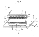
- Fig. 1 is a schematical exploded perspective view of an electric connector according to an embodiment of the present invention
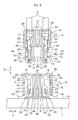
- Fig. 2 is a schematical exploded side view thereof.
- the connector of the present invention comprises a base connector 2 to be packaged on the surface 1a of a board 1 and a socket connector 4 to be connected to the end of a wire 3 in the connectable fashion.
- a reduced number of poles of the connector are shown for simplification.
- the base connector 2 comprises a horizontally elongated base housing 5 having a bottom surface 5a serving as a mounting surface for the surface 1a of the board 1, and a plurality of base contacts 7 (see Fig. 3) held by the base housing 5.
- Each base contact 7 includes a lead portion 19 to be soldered to a conductive member (not shown) on the surface 1a of the board 1.
- the socket connector 4 comprises a socket housing 9 having a pair of insertion projections 57 in a front half part 4a of the socket connector 4, and a plurality of socket contacts 10 (see Fig. 3) held by the socket housing 9.
- tiltable cantilever resilient arms 61 are provided at the right and left end portions of the socket housing 9, and locking hooks 62 of the housing 9 are provided at the distal ends of resilient arms 6.
- stepped engagement portions 63 engageable with the corresponding hooks 62 are provided at the right and left end portions of the base housing 5. As shown in Fig. 5, by the engagement of the hooks 62 with respective corresponding engagement portions 63, the socket housing 9 can be prevented from being pulled out from the base housing 5.
- the base housing 5 is rectangular in plan view as shown in Fig. 1 and is provided with a bottom wall 51 including the abovementioned bottom surface 5a as a mounting surface as shown in Figs. 2 and 3.
- the base housing 5 is provided with an opposed pair of side walls 52, 53 (see Fig. 3) and an opposed pair of end walls 54, 55 (see Fig. 2) surrounding the four sides of the bottom wall 51, and is further provided with an intermediate wall 56 extending from the bottom wall 51 in parallel with the pair of side walls 52, 53 (see Fig. 3).
- the pair of side walls 52, 53 are long walls elongated along the bottom wall 51, while the pair of end walls 54, 55 are short walls.
- the base housing 5 has a pair of insertion recesses 6 into which the pair of insertion projections 57 provided in the front half part 4a of the socket connector 4 are inserted in a predetermined fitting direction Z1 perpendicular to the bottom surface 5a as a mounting surface.
- the pair of insertion recesses 6 are elongated in parallel with the longitudinal direction X of the base housing 5 (direction perpendicular to the paper surface in Fig. 3) and are defined between the intermediate wall 56 and the corresponding side walls 52, 53 respectively.
- the pair of insertion recesses 6 are opened at a connection end surface 5b of the base housing 5 and wholly contain aligned plurality of fork-shaped base contacts 7 respectively to hold these two rows of base contacts 7.
- each base contact 7 protrudes toward each side of the base housing 5 and is soldered to the conductive member on the surface 1a of the board 1 as mentioned above.
- metal fixtures 8 fitted into channels (not shown) at both ends of the longitudinal direction X of the base housing 5 respectively are soldered to the conductive members on the surface 1a of the board 1 to prevent the base connector 2 from being twisted or the like.
- the socket housing 9, which is a housing for the socket connector 4, contains two rows of aligned socket contacts 10 and each of the socket contacts 10 is contained in a corresponding socket contact containing room 11.
- the socket contact 10 is one to which one end portion of the wire 3 is, for example, pressure-attached (or pressure-contacted).
- the end portion of the wire 3 connected to the socket contact 10 by pressure-attachment is led through each opening 12 of a rear surface 9a of the socket housing 9 into the corresponding socket contact containing room 11.
- the socket housing 9 defines open portions 13, 14 which outwardly and inwardly open the socket contact containing room 11. A part of the socket contact 10 opens to the outside through the open portions 13, 14.
- the base contact 7 has a fork-like shape comprising a semi-fixed piece portion 16 and a resilient piece portion 17 and is formed, for example, by punting from a metal plate.
- the resilient piece portions 17 thereof are disposed inside and the semi-fixed piece portions 16 thereof are disposed outside respectively.
- the resilient piece portions 17 of the two rows of the base contacts 7 are restrained from being resiliently deformed excessively beyond a predetermined amount by their contacting the intermediate wall 56.
- the base contact 7 has a connection portion 18 connecting the basic end portions of the semi-fixed piece portion 16 and the resilient piece portion 17 to each other.
- Each of the abovementioned lead portions 19 extends from the connected portion between the connection portion 18 and the semi-fixed piece portion 16 each sideways of the base connectors 2 to form substantially L-shape.
- the semi-fixed piece portion 16 and the resilient piece portion 17 are inserted into the insertion recess 6 through individual insertion holes 25, 26 respectively provided in an innermost wall 24 of the insertion recess 6.
- the semi-fixed piece portion 16 is disposed in such a manner that it is partly fitted into a guide channel 35 formed in the inside surface of the side walls 52, 53 of the base housing 5 defining the insertion recess 6.
- the semi-fixed piece portion 16 is disposed in such a manner that it substantially contacts the bottom surface of the guide channel 35 (for example, there is provided a microscopic space between the semi-fixed piece portions 16 and the bottom surface of the guide channel 35, and the amount of the space is 20 ⁇ 50 ⁇ m) and it functions mainly as a positioning reinforcement piece.
- the semi-fixed piece portion 16 serves for absorbing errors within this range, and in addition, when it is deformed beyond this range, it contacts the bottom surface of the guide channel 35 thereby to prevent the whole electric connector from being deformed and twisted in cooperation with the base housing 5.
- the resilient piece portion 17 is disposed in such a manner that it is partly fitted into a guide channel 37 formed in the side surface of the intermediate wall 56 defining the insertion recess 6. Since a sufficient space is provided between the resilient piece portion 17 and the bottom surface of the guide channel 37, the resilient piece portion 17 is resiliently deformable sideways. Therefore, the resilient piece portion 17 functions as a contact piece for securing the contact pressure with respect to a belowmentioned resilient tongue piece 33 of the corresponding socket contact 10. In addition, when the base housing 5 is much twisted, the resilient piece portion 17 contacts the bottom surface of the guide channel 37 to prevent the deformation of the electric connector.
- a mountain-shaped projection 22 protruding in the direction crossing the abovementioned fitting direction Z1, namely, toward the semi-fixed piece portion 16.
- a bite type projection 23 biting into the innermost wall 24 so as to prevent pull-put of the base contact 7 and fix the same.
- the socket contact 10 has a main part 27. At the rearmost portion of this main part 27, an insulation barrel 28 for clamping an insulation-coated portion 3a of the wire 3 is formed. And ahead of this insulation barrel 28, formed is a wire barrel 29 for clamping a core wire 3b of the wire 3.
- the front half part of the main part 27 comprises a first section 30, and second and third sections 31, 32 disposed on both sides of the first section 30. These first, second and third sections 30, 31, 32 form a ⁇ -shape in section.
- a resilient tongue piece 33 is folded back from a distal end of the first section 30 of the front half part of the main part 27. Further, in the first section 30, a contact lance 34 comprising a cut and pulled-off projection is provided so as to protrude on the opposite side of the resilient tongue piece 33. As shown in Fig. 3, the contact lance 34 contacts a contact surface 9b comprising a stepped portion of the socket housing 9 thereby to serve for preventing pull-out of the socket contact 10. Further, the contact lance 34, which outwardly protrudes through the open portion 13, resiliently presses the inside surface of the side walls 52, 53 defining the insertion recess 6 of the corresponding base housing 5 when the base connector 2 and the socket connector 4 are in the connected state as shown in Fig. 6. Thereby, the contact lance 34 also functions as a housing lance.
- the resilient tongue piece 33 has a mountain-shaped projection 39 protruding in a direction crossing the abovementioned predetermined fitting direction Z1 and engageable with the mountain-shaped projection 22 of the resilient piece portion 17.
- the two mountain-shaped projections 22, 39 ride across and come into engagement with the corresponding mountain-shaped projections 39, 22 respectively as shown in Fig. 6, so that a nice click is sensed by an operator in the connecting operation.
- the distal end portion 40 of the resilient piece tongue piece 33 is folded back on the first portion 30 side. And when the resilient tongue piece 33 is in the free state, the distal end portion 40 thereof is substantially in close contact with the first portion 30 of the main part 27. As a result, the resilient tongue piece 33 is supported at both ends, so that the resilient repulsive force of the resilient tongue piece 33 increases and a strong contact pressure can be obtained between the resilient tongue piece 33 and the resilient piece portion 17 of the base contact 7. In addition, even if the socket connector 4 is frequently inserted and pulled out, the resilient tongue piece 33 has an improved tolerance.
- so-called a board-to-wire and double (including two rows of contacts) vertical connector has such a structure that the fork-like base contact 7 resiliently holds the corresponding socket contact 10 therebetween in the lateral direction Y of the base housing 5, and therefore, if the wire 3 is obliquely pulled and twisted by a force in the abovementioned lateral direction Y as shown in two-dot-and-chain line in Fig. 6, a sufficient contact pressure can be ensured between the contacts 7, 10.
- the resilient piece portion 17 of the fork-like base contact 7 in one row is received by the intermediate wall 56 of the base housing 5 while the semi-fixed piece portion 16 of the base contact 7 in the other row is received by the side wall 52 or 53 of the base housing 5, so that the connector can be reinforced against a twist by a force in the abovementioned lateral direction Y.
- the main part 27 of the socket contact 10 is received through the semi-fixed piece portion 16 of the base contact 7 by the inside surface of the side walls 52, 53 of the base housing 5, and therefore, the connectors 2, 4 can be restrained from being twisted in the lateral direction without causing any trouble by the formation of the open portion 13.
- the connector has such a structure that the base contact 7 resiliently holds the socket contact 10 in the lateral direction Y as abovementioned, the contact pressure between the two contacts 7, 10 is hardly influenced if the wires 3 are obliquely pulled as shown in Fig. 5 and the contacts 7, 10 receive twist (pitch twist, pitching twist) by a force of the longitudinal direction X.
- both of the housings 5, 9 are locked at their longitudinal ends, so that so-called pitch twist itself hardly occurs.
- both of the contacts 7, 10 have resiliency, a sufficient amount of resilient deformation can be ensured at the connecting time, so that the operator can sense a strong click (touch of connection achievement) in the connecting operation.
- both of the contacts 7, 10 are formed of metal, a stronger click can be sensed in the connecting operation than a click made between both resin members.
- the present invention is not limited to the abovementioned embodiment but, for example, the open portion 13 can be omitted and in this case, a high strength can be achieved though the width become a little larger. Furthermore, the resilient piece portion 16 in the free state may be adapted to contact the bottom surface of the guide channel 35.
Landscapes
- Coupling Device And Connection With Printed Circuit (AREA)
- Details Of Connecting Devices For Male And Female Coupling (AREA)
Applications Claiming Priority (2)
| Application Number | Priority Date | Filing Date | Title |
|---|---|---|---|
| JP2003434949A JP2005196975A (ja) | 2003-12-26 | 2003-12-26 | コネクタ |
| JP2003434949 | 2003-12-26 |
Publications (1)
| Publication Number | Publication Date |
|---|---|
| EP1548890A1 true EP1548890A1 (de) | 2005-06-29 |
Family
ID=34545113
Family Applications (1)
| Application Number | Title | Priority Date | Filing Date |
|---|---|---|---|
| EP04258003A Withdrawn EP1548890A1 (de) | 2003-12-26 | 2004-12-21 | Elektrischer Verbinder |
Country Status (6)
| Country | Link |
|---|---|
| US (1) | US6971922B2 (de) |
| EP (1) | EP1548890A1 (de) |
| JP (1) | JP2005196975A (de) |
| KR (1) | KR20050067047A (de) |
| CN (1) | CN100486045C (de) |
| TW (1) | TWI340507B (de) |
Cited By (1)
| Publication number | Priority date | Publication date | Assignee | Title |
|---|---|---|---|---|
| WO2010005956A1 (en) * | 2008-07-07 | 2010-01-14 | Molex Incorporated | Board connector |
Families Citing this family (17)
| Publication number | Priority date | Publication date | Assignee | Title |
|---|---|---|---|---|
| JP4328709B2 (ja) * | 2004-11-01 | 2009-09-09 | 日本圧着端子製造株式会社 | 電気コネクタ |
| JP4115983B2 (ja) * | 2004-11-01 | 2008-07-09 | 日本圧着端子製造株式会社 | ブレードコンタクト |
| JP4471390B2 (ja) * | 2007-05-25 | 2010-06-02 | ヒロセ電機株式会社 | ケーブル用電気コネクタ及びこれに嵌合接続される基板用電気コネクタ |
| US7491095B1 (en) * | 2008-02-25 | 2009-02-17 | Enermax Technology Corporation | Power supply socket device |
| FR2956527B1 (fr) * | 2010-02-15 | 2012-09-21 | Tyco Electronics France Sas | Connecteur electrique comprenant une protuberance ou une poche de guidage avec un element de fixation flexible. |
| KR102028769B1 (ko) * | 2011-09-12 | 2019-10-04 | 케어스트림 헬스 인코포레이티드 | 이동식 라디오그래피 촬영 장치에 저장된 전기적 그리드 홀더와 감지기들을 위한 충전기 및 이를 이용하기 위한 방법 |
| CN103187651B (zh) * | 2011-12-27 | 2015-01-14 | 凡甲电子(苏州)有限公司 | 电连接器 |
| JP6249676B2 (ja) * | 2013-08-21 | 2017-12-20 | 宏致電子股▲ふん▼有限公司Aces Electronics Co.,Ltd. | 電気コネクタ |
| JP5849166B1 (ja) * | 2014-12-12 | 2016-01-27 | イリソ電子工業株式会社 | 基板間接続構造 |
| DE102015216632A1 (de) * | 2015-08-31 | 2017-03-02 | Te Connectivity Germany Gmbh | Anordnung zum Herstellen einer elektrischen Verbindung zwischen einem Flachkontakt und einem Hochstromleiter |
| JP6448505B2 (ja) * | 2015-10-02 | 2019-01-09 | モレックス エルエルシー | カードエッジコネクタ |
| US9877404B1 (en) * | 2017-01-27 | 2018-01-23 | Ironwood Electronics, Inc. | Adapter apparatus with socket contacts held in openings by holding structures |
| JP6738540B2 (ja) * | 2017-02-03 | 2020-08-12 | 住友電装株式会社 | 基板用コネクタ |
| CN107889412A (zh) * | 2017-09-21 | 2018-04-06 | 上海力信电气技术有限公司 | 控制板插线与插排兼容方法 |
| JP7164863B2 (ja) * | 2018-08-27 | 2022-11-02 | 日本圧着端子製造株式会社 | 電気コネクタ |
| JP7536659B2 (ja) * | 2021-01-05 | 2024-08-20 | 日本航空電子工業株式会社 | コネクタ組立体 |
| JP7655777B2 (ja) * | 2021-05-21 | 2025-04-02 | モレックス エルエルシー | 端子、電線コネクタ及び電線対基板コネクタ |
Citations (7)
| Publication number | Priority date | Publication date | Assignee | Title |
|---|---|---|---|---|
| EP0410491A1 (de) * | 1989-07-28 | 1991-01-30 | The Whitaker Corporation | Gelenkverbindung und elektrischer Verbinder mit einem an einer Gelenkverbindung angebrachten Einklinkarm |
| WO1996028866A1 (en) * | 1995-03-14 | 1996-09-19 | The Whitaker Corporation | Electrical receptacle assembly and spring contact therefor |
| WO1997045896A1 (en) * | 1996-05-30 | 1997-12-04 | The Whitaker Corporation | Surface mountable electrical connector |
| JPH10134886A (ja) * | 1996-10-29 | 1998-05-22 | Fujitsu Takamizawa Component Kk | コネクタ |
| US5931689A (en) * | 1997-08-06 | 1999-08-03 | Molex Incorporated | Electric connector assembly with improved locking characteristics |
| JP2000082519A (ja) * | 1998-09-04 | 2000-03-21 | Jst Mfg Co Ltd | コネクタ |
| US6257900B1 (en) * | 1999-10-15 | 2001-07-10 | Hon Hai Precision Ind. Co., Ltd. | Electrical connector with contacts having improved resiliency |
Family Cites Families (3)
| Publication number | Priority date | Publication date | Assignee | Title |
|---|---|---|---|---|
| JPH0584045U (ja) * | 1992-04-18 | 1993-11-12 | モレックス インコーポレーテッド | 薄型表面実装用電気コネクタ |
| US6328606B1 (en) * | 2000-05-12 | 2001-12-11 | Tyco Electronics Corporation | High density electrical connector system |
| JP3386783B2 (ja) * | 2000-07-14 | 2003-03-17 | 日本圧着端子製造株式会社 | 電気コネクタ及びソケットコネクタ |
-
2003
- 2003-12-26 JP JP2003434949A patent/JP2005196975A/ja active Pending
-
2004
- 2004-12-17 TW TW093139451A patent/TWI340507B/zh not_active IP Right Cessation
- 2004-12-17 CN CNB200410081851XA patent/CN100486045C/zh not_active Expired - Lifetime
- 2004-12-21 US US11/016,839 patent/US6971922B2/en not_active Expired - Lifetime
- 2004-12-21 EP EP04258003A patent/EP1548890A1/de not_active Withdrawn
- 2004-12-24 KR KR1020040111783A patent/KR20050067047A/ko not_active Ceased
Patent Citations (8)
| Publication number | Priority date | Publication date | Assignee | Title |
|---|---|---|---|---|
| EP0410491A1 (de) * | 1989-07-28 | 1991-01-30 | The Whitaker Corporation | Gelenkverbindung und elektrischer Verbinder mit einem an einer Gelenkverbindung angebrachten Einklinkarm |
| WO1996028866A1 (en) * | 1995-03-14 | 1996-09-19 | The Whitaker Corporation | Electrical receptacle assembly and spring contact therefor |
| JPH11502053A (ja) * | 1995-03-14 | 1999-02-16 | ザ ウィタカー コーポレーション | 電気リセプタクル組立体及びそのためのばねコンタクト |
| WO1997045896A1 (en) * | 1996-05-30 | 1997-12-04 | The Whitaker Corporation | Surface mountable electrical connector |
| JPH10134886A (ja) * | 1996-10-29 | 1998-05-22 | Fujitsu Takamizawa Component Kk | コネクタ |
| US5931689A (en) * | 1997-08-06 | 1999-08-03 | Molex Incorporated | Electric connector assembly with improved locking characteristics |
| JP2000082519A (ja) * | 1998-09-04 | 2000-03-21 | Jst Mfg Co Ltd | コネクタ |
| US6257900B1 (en) * | 1999-10-15 | 2001-07-10 | Hon Hai Precision Ind. Co., Ltd. | Electrical connector with contacts having improved resiliency |
Cited By (1)
| Publication number | Priority date | Publication date | Assignee | Title |
|---|---|---|---|---|
| WO2010005956A1 (en) * | 2008-07-07 | 2010-01-14 | Molex Incorporated | Board connector |
Also Published As
| Publication number | Publication date |
|---|---|
| US20050186855A1 (en) | 2005-08-25 |
| CN1638199A (zh) | 2005-07-13 |
| KR20050067047A (ko) | 2005-06-30 |
| JP2005196975A (ja) | 2005-07-21 |
| US6971922B2 (en) | 2005-12-06 |
| TWI340507B (en) | 2011-04-11 |
| CN100486045C (zh) | 2009-05-06 |
| TW200539518A (en) | 2005-12-01 |
Similar Documents
| Publication | Publication Date | Title |
|---|---|---|
| US6971922B2 (en) | Electric connector | |
| US5595509A (en) | Electrical connector with terminal position assurance system | |
| US7883362B2 (en) | Joint connector, joint terminal and a wiring harness with a joint connector | |
| US7048597B2 (en) | Female terminal for heavy current and female terminal for heavy current with shell | |
| JP2939867B2 (ja) | 金属製外壁構造をもつ電気コネクタ | |
| EP0108608A1 (de) | Zusammenbau eines elektrischen Verbinders | |
| JP2018139209A (ja) | 端子位置保証装置を有する電気コネクタ | |
| US5993268A (en) | Electrical connector with terminal retaining means | |
| US7048573B2 (en) | Plug-type connector and electric connector comprising the same | |
| EP3389149B1 (de) | Elektrischer steckverbinder | |
| US20070099520A1 (en) | Connecting terminal | |
| US7766697B2 (en) | Connector | |
| US6520779B1 (en) | Circuit member connection structure | |
| EP0768734A2 (de) | Elektrischer Steckverbinder | |
| US6676448B2 (en) | Connector | |
| US20010023142A1 (en) | Printed circuit board connector | |
| US5769670A (en) | Connector with rear holder | |
| US20050118884A1 (en) | Electrical contact element | |
| CN115377719A (zh) | 端子、电线连接器及线对板连接器 | |
| EP1204177B1 (de) | Verbinder zur Befestigung auf eine Leiterplatte und Anordnung zur Befestigung eines Verbinders auf eine Leiterplatte | |
| JP4876012B2 (ja) | プラグインコネクタ | |
| EP0929133B1 (de) | Anschlusselement für Keilsockellampe und Lampenfassung mit einem solchen Anschlusselement | |
| KR101076153B1 (ko) | 로크 기구가 달린 커넥터 | |
| JP3246894B2 (ja) | コネクタ | |
| JP4353433B2 (ja) | コネクタ |
Legal Events
| Date | Code | Title | Description |
|---|---|---|---|
| PUAI | Public reference made under article 153(3) epc to a published international application that has entered the european phase |
Free format text: ORIGINAL CODE: 0009012 |
|
| AK | Designated contracting states |
Kind code of ref document: A1 Designated state(s): AT BE BG CH CY CZ DE DK EE ES FI FR GB GR HU IE IS IT LI LT LU MC NL PL PT RO SE SI SK TR |
|
| AX | Request for extension of the european patent |
Extension state: AL BA HR LV MK YU |
|
| 17P | Request for examination filed |
Effective date: 20051215 |
|
| AKX | Designation fees paid |
Designated state(s): AT DE GB NL |
|
| 17Q | First examination report despatched |
Effective date: 20120111 |
|
| STAA | Information on the status of an ep patent application or granted ep patent |
Free format text: STATUS: THE APPLICATION IS DEEMED TO BE WITHDRAWN |
|
| 18D | Application deemed to be withdrawn |
Effective date: 20120522 |