EP1549821B1 - Centreur de tubage et procede de fabrication correspondant - Google Patents
Centreur de tubage et procede de fabrication correspondant Download PDFInfo
- Publication number
- EP1549821B1 EP1549821B1 EP03797130A EP03797130A EP1549821B1 EP 1549821 B1 EP1549821 B1 EP 1549821B1 EP 03797130 A EP03797130 A EP 03797130A EP 03797130 A EP03797130 A EP 03797130A EP 1549821 B1 EP1549821 B1 EP 1549821B1
- Authority
- EP
- European Patent Office
- Prior art keywords
- centralizer
- sidewall
- work piece
- ribs
- tubular
- Prior art date
- Legal status (The legal status is an assumption and is not a legal conclusion. Google has not performed a legal analysis and makes no representation as to the accuracy of the status listed.)
- Expired - Lifetime
Links
- 238000000034 method Methods 0.000 title claims abstract description 37
- 239000002184 metal Substances 0.000 claims abstract description 18
- 229910052751 metal Inorganic materials 0.000 claims abstract description 18
- 238000003780 insertion Methods 0.000 claims abstract description 3
- 230000037431 insertion Effects 0.000 claims abstract description 3
- 239000012530 fluid Substances 0.000 claims description 13
- 238000002788 crimping Methods 0.000 claims description 10
- 238000000576 coating method Methods 0.000 claims description 9
- 239000011248 coating agent Substances 0.000 claims description 8
- 238000007373 indentation Methods 0.000 claims description 3
- 238000007789 sealing Methods 0.000 claims description 3
- 239000000463 material Substances 0.000 description 12
- 238000005553 drilling Methods 0.000 description 11
- 229910000831 Steel Inorganic materials 0.000 description 5
- 239000010959 steel Substances 0.000 description 5
- 238000006073 displacement reaction Methods 0.000 description 4
- 238000009434 installation Methods 0.000 description 2
- 238000004519 manufacturing process Methods 0.000 description 2
- 239000004033 plastic Substances 0.000 description 2
- 229920003023 plastic Polymers 0.000 description 2
- 230000007704 transition Effects 0.000 description 2
- 239000000853 adhesive Substances 0.000 description 1
- 230000001070 adhesive effect Effects 0.000 description 1
- 230000015572 biosynthetic process Effects 0.000 description 1
- 238000007727 cost benefit analysis Methods 0.000 description 1
- 230000008878 coupling Effects 0.000 description 1
- 238000010168 coupling process Methods 0.000 description 1
- 238000005859 coupling reaction Methods 0.000 description 1
- 230000000694 effects Effects 0.000 description 1
- 229920001971 elastomer Polymers 0.000 description 1
- 239000000806 elastomer Substances 0.000 description 1
- -1 for example Chemical class 0.000 description 1
- 239000011440 grout Substances 0.000 description 1
- 238000005552 hardfacing Methods 0.000 description 1
- 239000007788 liquid Substances 0.000 description 1
- 238000003754 machining Methods 0.000 description 1
- 230000013011 mating Effects 0.000 description 1
- 150000002739 metals Chemical class 0.000 description 1
- 239000003208 petroleum Substances 0.000 description 1
- 229920002635 polyurethane Polymers 0.000 description 1
- 239000004814 polyurethane Substances 0.000 description 1
- 230000002250 progressing effect Effects 0.000 description 1
- XLYOFNOQVPJJNP-UHFFFAOYSA-N water Substances O XLYOFNOQVPJJNP-UHFFFAOYSA-N 0.000 description 1
- 238000003466 welding Methods 0.000 description 1
Images

Classifications
-
- E—FIXED CONSTRUCTIONS
- E21—EARTH OR ROCK DRILLING; MINING
- E21B—EARTH OR ROCK DRILLING; OBTAINING OIL, GAS, WATER, SOLUBLE OR MELTABLE MATERIALS OR A SLURRY OF MINERALS FROM WELLS
- E21B17/00—Drilling rods or pipes; Flexible drill strings; Kellies; Drill collars; Sucker rods; Cables; Casings; Tubings
- E21B17/10—Wear protectors; Centralising devices, e.g. stabilisers
- E21B17/1078—Stabilisers or centralisers for casing, tubing or drill pipes
-
- B—PERFORMING OPERATIONS; TRANSPORTING
- B21—MECHANICAL METAL-WORKING WITHOUT ESSENTIALLY REMOVING MATERIAL; PUNCHING METAL
- B21D—WORKING OR PROCESSING OF SHEET METAL OR METAL TUBES, RODS OR PROFILES WITHOUT ESSENTIALLY REMOVING MATERIAL; PUNCHING METAL
- B21D17/00—Forming single grooves in sheet metal or tubular or hollow articles
-
- B—PERFORMING OPERATIONS; TRANSPORTING
- B21—MECHANICAL METAL-WORKING WITHOUT ESSENTIALLY REMOVING MATERIAL; PUNCHING METAL
- B21D—WORKING OR PROCESSING OF SHEET METAL OR METAL TUBES, RODS OR PROFILES WITHOUT ESSENTIALLY REMOVING MATERIAL; PUNCHING METAL
- B21D26/00—Shaping without cutting otherwise than using rigid devices or tools or yieldable or resilient pads, i.e. applying fluid pressure or magnetic forces
- B21D26/02—Shaping without cutting otherwise than using rigid devices or tools or yieldable or resilient pads, i.e. applying fluid pressure or magnetic forces by applying fluid pressure
- B21D26/033—Deforming tubular bodies
-
- E—FIXED CONSTRUCTIONS
- E21—EARTH OR ROCK DRILLING; MINING
- E21B—EARTH OR ROCK DRILLING; OBTAINING OIL, GAS, WATER, SOLUBLE OR MELTABLE MATERIALS OR A SLURRY OF MINERALS FROM WELLS
- E21B17/00—Drilling rods or pipes; Flexible drill strings; Kellies; Drill collars; Sucker rods; Cables; Casings; Tubings
- E21B17/10—Wear protectors; Centralising devices, e.g. stabilisers
- E21B17/1057—Centralising devices with rollers or with a relatively rotating sleeve
- E21B17/1064—Pipes or rods with a relatively rotating sleeve
-
- Y—GENERAL TAGGING OF NEW TECHNOLOGICAL DEVELOPMENTS; GENERAL TAGGING OF CROSS-SECTIONAL TECHNOLOGIES SPANNING OVER SEVERAL SECTIONS OF THE IPC; TECHNICAL SUBJECTS COVERED BY FORMER USPC CROSS-REFERENCE ART COLLECTIONS [XRACs] AND DIGESTS
- Y10—TECHNICAL SUBJECTS COVERED BY FORMER USPC
- Y10T—TECHNICAL SUBJECTS COVERED BY FORMER US CLASSIFICATION
- Y10T29/00—Metal working
- Y10T29/49—Method of mechanical manufacture
-
- Y—GENERAL TAGGING OF NEW TECHNOLOGICAL DEVELOPMENTS; GENERAL TAGGING OF CROSS-SECTIONAL TECHNOLOGIES SPANNING OVER SEVERAL SECTIONS OF THE IPC; TECHNICAL SUBJECTS COVERED BY FORMER USPC CROSS-REFERENCE ART COLLECTIONS [XRACs] AND DIGESTS
- Y10—TECHNICAL SUBJECTS COVERED BY FORMER USPC
- Y10T—TECHNICAL SUBJECTS COVERED BY FORMER US CLASSIFICATION
- Y10T29/00—Metal working
- Y10T29/49—Method of mechanical manufacture
- Y10T29/49805—Shaping by direct application of fluent pressure
Definitions
- the present invention relates to centralizers attached to pipe placed in boreholes.
- the invention discloses a method of hydroforming centralizers and means of their attachment to pipe.
- GB 2197008A shows a cast tubular centralizer carrying relatively thick ribs.
- Canadian patent application 2350681 filed June 15, 2001 in the name of TESCO Corporation, the demands of drilling with casing lead to the need for inexpensive casing centralizers which are rugged, for example resistant to rib failure, comparatively easy to attach to the casing and able to withstand drilling rotation sufficient to complete at least one well.
- Hydroforming is a manufacturing process that has been used to work metal. Processes for hydroforming and members worked thereby are described in US published Application 2001/0006109, published July 5, 2001 naming the present inventor, and International Patent Applications WO 02/31312, published April 18, 2002, and WO 98/46382, October 22, 1998. Such centralizers are also useful for applications beyond casing drilling.
- a hydroformed centralizer and method of manufacture has been invented.
- the centralizer is suitable for installation on pipe, such as would be useful in well bore drilling and casing operations.
- a centralizer comprising a generally tubular body having a central opening sufficiently large to allow insertion therethrough of a pipe having an external diameter; a sidewall including an inner-facing surface directed to the central opening and an outer-facing surface, the centralizer being wherein the sidewall is of substantially uniform thickness, there being a plurality of outwardly protruding ribs placed in the sidewall with some thinning of the sidewall at each rib.
- the inner-facing surface includes indentations substantially conforming to the position and shape of the ribs.
- tubular body includes a first end and an opposite end and the ribs are spaced back from the first end.
- the ribs (7) are spaced back from the opposite end (4, 4a).
- the first end is formed to permit attachment therethrough to the pipe.
- the first end is formed to accommodate crimping attachment.
- the centralizer includes a coating on at least a portion of the inner-facing surface.
- the centralizer is formed of metal.
- the ribs are provided with a wear resistant coating.
- a method of forming a centralizer comprising the steps of: providing a length of a metal tubular work piece including a work piece sidewall selected to define the sidewall of the centralizer and including an inner bore selected to define the central opening of the centralizer, wherein the method comprises placing the metal tubular work piece inside a confining surface comprised of mold elements, the mold elements including mold cavities spaced and shaped in the configuration of desired centralizer ribs, the mold elements being supported substantially against expansion radially outward from their position about the tubular work piece; applying sufficient pressure to the work piece sidewall through the inner bore to force the tubular work piece sidewall radially outward against the confining surface and into the mold cavities to plastically deform the work piece sidewall to form centralizer ribs on the sidewall; and removing the tubular work piece from the confining surface.
- the pressure is fluid pressure which may be selected by hydraulic pressure or air pressure.
- the pressure is hydraulic pressure and the ribs are hydro-formed.
- the mold elements are substantially cylindrical.
- the mold elements contain slits to permit their circumferential expansion for removal thereof from the centralizer after forming.
- the mold elements abut circumferentially at adjacent ends to form the confining surface.
- each mold element defines a portion of a cavity.
- the step of placing includes inserting a mandrel into the central opening of the tubular work piece such that a space is formed between the mandrel and the work piece sidewall, sealing about the space and positioning the tubular work piece in the confining surface and the step of applying sufficient pressure includes introducing fluid pressure to the space.
- the sidewall formed with ribs is of substantially uniform thickness.
- the method further comprises applying a coating to the centralizer inner surface once the centralizer has been removed from the confining surface.
- the method further comprises treating the ribs to increase their wear resistance once the tubular work piece has been removed from the confining surface.
- Preferably removing the centralizer from the confining surface includes expanding the mold elements to overcome their hoop stress.
- the ribs are formed to protrude smoothly from the sidewall cylindrical outer surface.
- the mold elements are separable from each other by way of circumferential split.
- the means employed for attachment may be varied according to the needs of the application.
- the centralizer body is provided with at least one cylindrical interval suitable for attachment by the method of crimping as taught in the aforementioned Canadian Application 2350681.
- the hydroformed centralizer can be installed between stop rings affixed to the pipe, as commonly implemented for casing running.
- the stop rings may be fixed to the pipe by the method of crimping or by other means generally known to the industry such as set screws threadably mounted in the side wall of the stop rings.
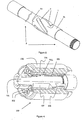
- a hydroformed centralizer is provided as shown in Figures 1 to 3, for placement on a pipe as shown in Figure 9.
- a centralizer 1 is provided in its preferred embodiment having a metal body sidewall 6 defining an internal bore 2, cylindrical ends 3, 4, and a main body interval into which outwardly projecting hydroformed ribs 7 are formed. While three ribs are shown, any number can be formed on the centralizer. In its preferred embodiment, one or both of cylindrical ends 3, 4 can provide intervals suitable for crimping, if it is desired that the centralizer be installable for crimping.
- Ribs 7 can be evenly spaced around the main body interval and, in this illustrated embodiment, each rib extends along at least a portion of the length of the centralizer helically as commonly known to the industry.
- the ribs can be suitably shaped to accommodate the structural and flow requirements encountered in well bores and to stand the main cylindrical surface and ends 3, 4 from the borehole wall. As such the ribs provide a bearing surface 8 at their upper limits.
- the number, length and pitch of the rib helixes can be arranged so that the starting circumferential position of each rib overlaps the ending circumferential position of at least one adjacent rib.
- the bearing surfaces 8 may be provided with a wear resistance coating such as hardfacing to protect the ribs 7 from wear against the borehole wall.
- the internal bore 2 can wear against the pipe.
- the surface defining the internal bore may be provided over all or a portion thereof with a suitable friction reducing coating 2a such as for example of polyurethane.
- ribs 7 in the tubular wall is supported through provision of a hydroforming process.
- the hydroforming process allows ribs to be placed in the sidewall of centralizer 1 with some thinning of the sidewall at the rib.
- the specific forming method expands the rib outward while constraining the remainder of the tube.
- the volume of the material in the region of the rib therefore, stays constant and some thinning must occur to accommodate the greater surface area/perimeter length of the rib compared to the original tube wall.
- the amount of thinning actually possible without failing the material depends on various properties of the material used to form the centralizer. As an example, when using steel the thinning is in the order of about 25% such that the formed wall thickness is 75% of the original wall thickness.
- the inner surface of the side wall is also deformed and includes indentations 5 that substantially follow the configuration of the outer ribs.
- the ribs can be formed with smooth, gradual, rather than sharp, surface transitions at the base and throughout the ribs.
- the hydroforming process includes placing a length of metal tubular work piece having a sidewall.
- the material of the tubular work piece is selected to accommodate plastic deformation and substantially retain the effects hydroforming, while being useful in downhole environments.
- the centralizer is formed of ductile metals such as, for example, steel.
- wall thickness combined with the material strength must provide sufficient strength to react the eccentering and perhaps lateral drilling forces encountered by the tubular. These forces vary significantly depending on tubular size, hole geometry, location in the hole, drilling or running, etc.
- the wall thickness of the material for forming the centralizer is greater than about 0.16cm ( 1 / 16 " ).
- an upper limit for steel wall thickness is about 1.27cm (1 ⁇ 2 " ) for petroleum or even geothermal applications.
- the material is steel having a wall thickness of 0.635cm (1 ⁇ 4 " ).
- the tubular work piece is positioned inside a confining surface comprised of mold elements having cavities spaced and shaped in the configuration of the desired side wall protruding ribs.
- the confining surface can be generally cylindrical and positioned to generally align with the mid-section of the tubular work piece.
- the confining surface can be configured to support by cylindrical confinement opposite the end sections of the tubular work piece.
- the confining surface is contained within a support that holds the mold elements in position.
- the support can be a confining tube that holds the mold elements against movement radially outwardly away from the tubular work piece.
- the tubular elements are positioned about the tubular work piece, sufficient internal pressure can be applied against the inner surface of the side wall to force, as by inflating, the tubular sidewall radially outward against the confining surface and into the mold cavities and thus plastically form protrusions or ribs projecting outwardly from the side wall of the tubular work piece.
- the pressure is generated as fluid pressure, as by use of liquids contained to act at high pressures against the side wall.
- the ribs are formed, while substantially preserving the original tubular length.
- the formed centralizer can be removed from the forming apparatus including the confining surface and its support. Removal of the mold elements from their support may require some force due to them becoming tightly jammed therein during hydroforming.
- Removal may be facilitated by providing a close fitting tapered collet between the support and the mold elements and means to axially displace the collet in the direction allowing radial expansion.
- the centralizer can then be treated, if required, by various means such as cropping, machining or applying coatings to improve wear resistance or to reduce friction.
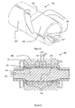
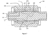
- the apparatus includes an assembly of close fitting largely cylindrical components sized to fit within and about the tubular work piece to be handled. Beginning with the innermost and progressing outward, these components are: a mandrel 101, a mold assembly 103 comprised of elements 107, 108, an externally tapered collet 104 comprised of an assembly of jaws 105 and a confining support vessel or bell 106 internally tapered to mate with the collet.
- a means to apply axial displacement between collet 104 and bell 106 can be provided, such as a double acting hydraulic actuator (not shown). As will be apparent to one skilled in the art the axial displacement is converted to radial displacement by the collet jaws 105 moving in contact with the bell 106 facilitating installation and removal of the close fitting parts.
- a tubular work piece 102 For hydroforming, a tubular work piece 102, from which a centralizer is to be formed, is positioned between mandrel 101 and mold assembly 103.
- the mold assembly 103 is comprised of two elements 107, 108 mating at split line 112 and having three helical cavities 109, generally shaped as the inverse of the desired rib geometry.
- the cavities can be closed or open through the mold, as shown.
- the form of the cavities dictates the shape of the ribs that will be formed from the mold.
- the cavities can be formed to have abrupt edges to cause the ribs (Figure 8) to protrude abruptly, with edges of lower radius, from the cylindrical surface of the side wall.
- the cavities can have more gradual side walls ( Figure 5) with large radiused edges to cause the ribs ( Figure 1) to have a smooth transition from the cylindrical surface of the side wall.
- each mold element can form a portion of a cavity so that the elements are not engaged on the centralizer by the protrusion of a rib into a cavity.
- the mandrel 101 is provided with internal seals 110 sized to seal against the inside bore 2 of the work piece blank 102 and a fluid entry port 111 open to the mandrel outer surface between seals 110.
- any fluid applied through port 111 is thus contained by the work piece, mandrel 101 and seals 110, these components all being in sealing engagement.
- suitable means such as may be provided by water, a high pressure gas, elastomers or hydraulic fluid.
- the fluid employed to apply hydroforming pressure can be any fluid capable of transferring pressure with relatively little resistance from shear stress.
- Pressures required to hydroform depend, for example, on the strength of the material to be formed and the radius of the curvature to which the wall is formed. In one embodiment, pressures are from 100 to 200 Mpa (15,000 to 30,000 psi). Seals 110, etc. must be capable of containing such pressures.
- This movement may be readily prevented by application of axial load or other suitable means of restraint between the collet jaws 105 and bell 106.
- the mandrel 101 Upon removal of the forming pressure, the mandrel 101 is readily removed, however a residual radial stress or interference may exist between the work piece 102 and mold 103 tending to resist removal of the work piece and the mold from collet 104.
- This radial stress is relieved by appropriate displacement of the collet relative to the bell enabling removal of the work piece 102 together with the mold elements 107, 108, since the formed ribs 7 are interlocking with the mold cavities 109 after forming.
- the mold elements 107, 108 may be removed from the centralizer formed from work piece 102.
- a hydroformed centralizer can be installed using various means onto a pipe for use in a wellbore.
- means of mounting the centralizer body on a metal pipe can allow free rotation of the hydroformed centralizer on the metal pipe.
- the means of mounting can limit the centralizer's range of axial travel.
- mounting can include placement of the centralizer on the metal pipe between two surfaces upset sufficiently with respect to the metal pipe external diameter to abut the ends of the centralizer body.
- the abutting surfaces typically provided by the shoulders of stop rings placed coaxially on the pipe on either side of the centralizer, the stop rings being fixed to the metal pipe by means of set screws, bonding or crimping.
- the means of crimping the stop rings can follow the teachings provided in Cdn. App. 2350681.
- the selected metal pipe can be, for example, casing for drilling or lining a borehole or drill pipe.
- the hydroformed centralizer can be installed to provide axial load and torque transfer by securing the centralizer to move both rotationally and axially with the pipe on which it is attached.
- the internal bore 2 of the formed centralizer body 1 can be arranged to loosely fit over at least one end of a pipe, shown as a threaded and coupled casing joint 9. This allows the centralizer to be readily placed somewhere along the length of the casing joint 9.
- the centralizers are free to rotate and are constrained to slide between the couplings connecting the casing joints, which method of incorporating centralizers into a string is well known in the industry.
- the centralizer can be fixed to the casing by crimping one or both of the end intervals 3a, 4a onto the casing as described in Cdn. App. 2350681.
- the material of the centralizer body 1 in one or both of the end intervals 3a, 4a can be selected to preferably have its elastic limit less than that of the casing joint 9.
- one or both of the centralizer end intervals may be provided with set screws (not shown). Once positioned on the pipe, the set screws are tightened to fix the centralizer in place, which method of attachment is well known to the industry.
- the centralizer may be secured by use of welding or by injecting grout or other adhesive into the interface between the centralizer bore and casing, which method of affixing centralizers is also known in the art.
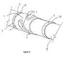
- Figure 9 shows cylindrical stop rings 10 provided and placed on the pipe to secure the centralizer 1 therebetween.
- the stop rings 10 are affixed to the casing in a manner preventing axial sliding.
- the stop rings are provided with set screws 11 and affixed to the pipe in a manner well known to the industry.
- the stop rings 10 are provided without set screws 11 and made from a ductile material suitable for attachment to the pipe by crimping.
Landscapes
- Engineering & Computer Science (AREA)
- Mining & Mineral Resources (AREA)
- Mechanical Engineering (AREA)
- Life Sciences & Earth Sciences (AREA)
- Geology (AREA)
- Physics & Mathematics (AREA)
- Fluid Mechanics (AREA)
- General Life Sciences & Earth Sciences (AREA)
- Environmental & Geological Engineering (AREA)
- Geochemistry & Mineralogy (AREA)
- Earth Drilling (AREA)
- Shaping Metal By Deep-Drawing, Or The Like (AREA)
- Golf Clubs (AREA)
- Forging (AREA)
- Superconductors And Manufacturing Methods Therefor (AREA)
- Tires In General (AREA)
- Rigid Pipes And Flexible Pipes (AREA)
- Peptides Or Proteins (AREA)
Claims (24)
- Centreur (1) comprenant un corps généralement tubulaire ayant une ouverture centrale (2) suffisamment large pour permettre d'y insérer un tube (9) ayant un diamètre extérieur ; une paroi latérale (6) comportant une surface tournée vers l'intérieur dirigée vers l'ouverture centrale et une surface tournée vers l'extérieure, le centreur étant caractérisé en ce que la paroi latérale a une épaisseur substantiellement uniforme, une pluralité de nervures saillant vers l'extérieur (7) étant placées dans la paroi latérale, par hydroformage de la paroi latérale, avec un amincissement de la paroi latérale au niveau de chaque nervure.
- Centreur selon la revendication 1, dans lequel la surface tournée vers l'intérieur comporte des indentations (5) correspondant substantiellement à la position et la forme des nervures.
- Centreur selon la revendication 1, dans lequel le corps tubulaire comporte une première extrémité (3, 3a) et une extrémité opposée (4, 4a) et les nervures (7) sont espacées en retrait de la première extrémité.
- Centreur selon la revendication 3, dans lequel les nervures (7) sont espacées en retrait de l'extrémité opposée (4, 4a).
- Centreur selon la revendication 3 ou 4, dans lequel la première extrémité (3, 3a) est formée pour permettre une fixation au tube à travers elle.
- Centreur selon la revendication 5, dans lequel la première extrémité (3, 3a) est formée pour recevoir une fixation par sertissage.
- Centreur selon l'une quelconque des revendications précédentes, comportant un revêtement (2a) sur au moins une portion de la surface tournée vers l'intérieur.
- Centreur selon l'une quelconque des revendications précédentes, formé de métal.
- Centreur selon l'une quelconque des revendications précédentes, dans lequel les nervures (7) sont pourvues d'un revêtement résistant à l'usure.
- Procédé de formation d'un centreur comprenant les étapes consistant à : fournir une longueur de pièce tubulaire métallique (102) comportant une paroi latérale de pièce sélectionnée pour définir la paroi latérale (6) du centreur et comportant un alésage interne sélectionné pour définir l'ouverture centrale (2) du centreur, caractérisé en ce que le procédé comprend l'étape consistant à positionner la pièce tubulaire métallique à l'intérieur d'une surface de confinement constituée d'éléments de moule (107, 108), les éléments de moule comportant des cavités de moule (109) espacées et formées à la configuration des nervures souhaitées (7) pour le centreur, les éléments de moule étant supportés substantiellement pour éviter leur expansion radialement vers l'extérieur depuis leur position autour de la pièce tubulaire ; appliquer une pression suffisante à la paroi latérale de la pièce à travers l'alésage interne pour forcer la paroi latérale de la pièce tubulaire radialement vers l'extérieur contre la surface de confinement et dans les cavités du moule pour déformer plastiquement la paroi latérale de la pièce pour former les nervures (7) du centreur sur la paroi latérale ; et enlever la pièce tubulaire de la surface de confinement.
- Procédé selon la revendication 10, dans lequel la pression est une pression de fluide.
- Procédé selon la revendication 11, dans lequel la pression de fluide est choisie parmi une pression hydraulique ou une pression d'air.
- Procédé selon la revendication 11, dans lequel la pression est une pression hydraulique et les nervures (7) sont hydroformées.
- Procédé selon l'une quelconque des revendications 10 à 13, dans lequel les éléments de moule (107, 108) sont substantiellement cylindriques.
- Procédé selon la revendication 14, dans lequel les éléments de moule (107, 108) contiennent des fentes (113) pour permettre leur expansion circonférentielle pour les enlever du centreur (1) après le formage.
- Procédé selon l'une quelconque des revendications 10 à 15, dans lequel les éléments de moule viennent buter circonférentiellement aux extrémités adjacentes pour former la surface de confinement.
- Procédé selon l'une quelconque des revendications 10 à 16, dans lequel chaque élément de moule (107, 108) définit une portion d'une cavité (109).
- Procédé selon l'une quelconque des revendications 10 à 17, dans lequel l'étape de mise en place comporte l'insertion d'un mandrin (101) dans l'ouverture centrale de la pièce tubulaire (102) de sorte qu'un espace soit formé entre le mandrin et la paroi latérale de la pièce, scellant l'espace et positionnant la pièce tubulaire dans la surface de confinement et l'étape d'application d'une pression suffisante inclut l'introduction de pression de fluide dans l'espace.
- Procédé selon l'une quelconque des revendications 10 à 18, dans lequel lors de l'enlèvement du centreur de la surface de confinement, la paroi latérale formée avec les nervures (7) a une épaisseur substantiellement uniforme.
- Procédé selon l'une quelconque des revendications 10 à 19, comprenant en outre l'application d'un revêtement (2a) sur la surface interne du centreur une fois que le centreur a été enlevé de la surface de confinement.
- Procédé selon l'une quelconque des revendications 10 à 20, comprenant en outre le traitement des nervures (7) pour augmenter leur résistance à l'usure une fois que la pièce tubulaire a été enlevée de la surface de confinement.
- Procédé selon l'une quelconque des revendications 18 à 21, dans lequel l'enlèvement du centreur de la surface de confinement inclut l'expansion des éléments de moule (107, 108) pour surmonter leur contrainte périphérique.
- Procédé selon l'une quelconque des revendications 19 à 22, dans lequel les nervures (7) sont formées de manière à faire saillie de manière uniforme depuis la surface extérieure cylindrique de la paroi latérale.
- Procédé selon l'une quelconque des revendications 19 à 23, dans lequel les éléments de moule peuvent être séparés les uns des autres par le biais de la fente circonférentielle.
Applications Claiming Priority (3)
| Application Number | Priority Date | Filing Date | Title |
|---|---|---|---|
| CA2404577 | 2002-09-23 | ||
| CA2404577A CA2404577C (fr) | 2002-09-23 | 2002-09-23 | Centreur de tuyau et methode de formage |
| PCT/CA2003/001392 WO2004027207A1 (fr) | 2002-09-23 | 2003-09-23 | Centreur de tubage et procede de fabrication correspondant |
Publications (2)
| Publication Number | Publication Date |
|---|---|
| EP1549821A1 EP1549821A1 (fr) | 2005-07-06 |
| EP1549821B1 true EP1549821B1 (fr) | 2006-11-22 |
Family
ID=32000086
Family Applications (1)
| Application Number | Title | Priority Date | Filing Date |
|---|---|---|---|
| EP03797130A Expired - Lifetime EP1549821B1 (fr) | 2002-09-23 | 2003-09-23 | Centreur de tubage et procede de fabrication correspondant |
Country Status (9)
| Country | Link |
|---|---|
| US (1) | US7814633B2 (fr) |
| EP (1) | EP1549821B1 (fr) |
| AT (1) | ATE346220T1 (fr) |
| AU (1) | AU2003266077A1 (fr) |
| CA (1) | CA2404577C (fr) |
| DE (1) | DE60309908T2 (fr) |
| DK (1) | DK1549821T3 (fr) |
| NO (1) | NO331180B1 (fr) |
| WO (1) | WO2004027207A1 (fr) |
Families Citing this family (24)
| Publication number | Priority date | Publication date | Assignee | Title |
|---|---|---|---|---|
| CA2353249A1 (fr) | 2001-07-18 | 2003-01-18 | Maurice William Slack | Centreur de tuyau et methode de fixation |
| US7361411B2 (en) | 2003-04-21 | 2008-04-22 | Att Technology, Ltd. | Hardfacing alloy, methods, and products |
| NO326223B1 (no) | 2003-10-29 | 2008-10-20 | Weatherford Lamb | Apparat og fremgangsmate for a redusere borevibrasjon ved boring med fôringsror |
| GB2430952B (en) * | 2003-10-29 | 2007-09-26 | Weatherford Lamb | Methods of forming a centraliser |
| CA2523106C (fr) * | 2004-10-12 | 2011-12-06 | Weatherford/Lamb, Inc. | Methodes et appareil de fabrication de materiel tubulaire expansible |
| AR066071A1 (es) * | 2008-04-16 | 2009-07-22 | Siderca Sa Ind & Com | Un centralizador para elementos tubulares fabricado apartir de dos materiales y un procedimiento para fabricar dicho centralizador. |
| US8167034B2 (en) * | 2008-06-19 | 2012-05-01 | Offshore Manufacturing & Design, Llc | Device for centering a well casing |
| WO2010127233A2 (fr) * | 2009-05-01 | 2010-11-04 | Baker Hughes Incorporated | Trépans de tubage, ensembles de forage et procédés destinés à être utilisés dans la formation de puits de forage avec un tubage extensible |
| WO2011059694A1 (fr) * | 2009-11-13 | 2011-05-19 | Wwt International, Inc. | Manchon non rotatif pour trou découvert et ensemble correspondant |
| USD674818S1 (en) | 2011-10-28 | 2013-01-22 | Top-Co Cementing Products Inc. | Casing centralizer |
| USD664568S1 (en) * | 2011-10-28 | 2012-07-31 | Top-Co Cementing Products, Inc. | Casing centralizer |
| USD663750S1 (en) * | 2011-10-28 | 2012-07-17 | Top-Co Cementing Products Inc. | Casing centralizer |
| USD665825S1 (en) * | 2011-10-28 | 2012-08-21 | Top-Co Cementing Products Inc. | Casing centralizer |
| USD674817S1 (en) | 2011-10-28 | 2013-01-22 | Top-Co Cementing Products Inc. | Casing centralizer |
| USD665824S1 (en) * | 2011-10-28 | 2012-08-21 | Top-Co Cementing Products Inc. | Casing centralizer |
| USD849800S1 (en) | 2012-04-04 | 2019-05-28 | Summit Energy Services, Inc. | Casing centralizer having spiral blades |
| USD676464S1 (en) * | 2012-04-04 | 2013-02-19 | Mitchel D. Hansen | Casing centralizer having straight blades |
| JP6137512B2 (ja) | 2012-11-08 | 2017-05-31 | デーナ、オータモウティヴ、システィムズ、グループ、エルエルシー | ドライブシャフト管を形成するための方法 |
| US10100588B2 (en) * | 2012-11-29 | 2018-10-16 | Per Angman | Mixed form tubular centralizers and method of use |
| WO2014082183A1 (fr) * | 2012-11-29 | 2014-06-05 | Per Angman | Centralisateur de tubulure |
| WO2014105544A1 (fr) * | 2012-12-31 | 2014-07-03 | Shell Oil Company | Système sous-marin à conduite de transport d'hydrocarbures |
| US9982490B2 (en) | 2013-03-01 | 2018-05-29 | Baker Hughes Incorporated | Methods of attaching cutting elements to casing bits and related structures |
| US20140311756A1 (en) * | 2013-04-22 | 2014-10-23 | Rock Dicke Incorporated | Pipe Centralizer Having Low-Friction Coating |
| CN111691831B (zh) * | 2020-05-25 | 2022-07-08 | 上海大学 | 一种大尺寸井眼稳定器母扣防失效方法 |
Family Cites Families (18)
| Publication number | Priority date | Publication date | Assignee | Title |
|---|---|---|---|---|
| US349718A (en) * | 1886-09-28 | hollerith | ||
| DE1002423B (de) * | 1955-10-08 | 1957-02-14 | Licentia Gmbh | Verfahren zur Herstellung flexibler Hohlleiter zur UEbertragung sehr hoher Frequenzen |
| DE3004838C2 (de) * | 1980-02-09 | 1984-09-13 | Benteler-Werke Ag Werk Neuhaus, 4790 Paderborn | Vorrichtung zur Herstellung eines Rohrkörpers mit Querwellen |
| US4763503A (en) * | 1985-12-31 | 1988-08-16 | Hughes Robert W | Apparatus for making a cam shaft |
| BR8700248A (pt) * | 1986-10-30 | 1988-05-24 | Raymond F Mikolajczyk | Centrador de tubo de revestimento |
| GB9703608D0 (en) * | 1997-02-21 | 1997-04-09 | Downhole Products Plc | Casing centraliser |
| EA001238B1 (ru) | 1997-04-16 | 2000-12-25 | Косма Интернэшнл Инк. | Пресс для гидроформинга высокого давления |
| US5992525A (en) * | 1998-01-09 | 1999-11-30 | Halliburton Energy Services, Inc. | Apparatus and methods for deploying tools in multilateral wells |
| US6409226B1 (en) * | 1999-05-05 | 2002-06-25 | Noetic Engineering Inc. | “Corrugated thick-walled pipe for use in wellbores” |
| US6497030B1 (en) * | 1999-08-31 | 2002-12-24 | Dana Corporation | Method of manufacturing a lead screw and sleeve mechanism using a hydroforming process |
| CA2328190C (fr) * | 1999-12-14 | 2006-02-07 | Trent Michael Victor Kaiser | Dispositif d'ancrage exterieur pour tubage |
| GB0001435D0 (en) | 2000-01-22 | 2000-03-08 | Downhole Products Plc | Centraliser |
| GB0005740D0 (en) | 2000-03-10 | 2000-05-03 | Downhole Products Plc | Centraliser |
| GB0015020D0 (en) | 2000-06-20 | 2000-08-09 | Downhole Products Plc | Centraliser |
| US6305204B1 (en) * | 2000-07-13 | 2001-10-23 | The Boeing Company | Bulge forming machine |
| GB0024909D0 (en) | 2000-10-11 | 2000-11-22 | Springer Johann | Drill string member |
| KR100789014B1 (ko) * | 2000-10-19 | 2007-12-26 | 코스마 인터내셔널 인크. | 관형 부품을 하이드로포밍하기 위한 장치 및 방법 |
| JP4057297B2 (ja) * | 2002-01-08 | 2008-03-05 | 日本発条株式会社 | ベローズ及びその製造方法 |
-
2002
- 2002-09-23 CA CA2404577A patent/CA2404577C/fr not_active Expired - Fee Related
-
2003
- 2003-09-23 WO PCT/CA2003/001392 patent/WO2004027207A1/fr not_active Ceased
- 2003-09-23 AT AT03797130T patent/ATE346220T1/de not_active IP Right Cessation
- 2003-09-23 EP EP03797130A patent/EP1549821B1/fr not_active Expired - Lifetime
- 2003-09-23 DE DE60309908T patent/DE60309908T2/de not_active Expired - Lifetime
- 2003-09-23 DK DK03797130T patent/DK1549821T3/da active
- 2003-09-23 US US10/528,277 patent/US7814633B2/en not_active Expired - Lifetime
- 2003-09-23 AU AU2003266077A patent/AU2003266077A1/en not_active Abandoned
-
2005
- 2005-04-22 NO NO20051990A patent/NO331180B1/no not_active IP Right Cessation
Also Published As
| Publication number | Publication date |
|---|---|
| NO331180B1 (no) | 2011-10-24 |
| ATE346220T1 (de) | 2006-12-15 |
| DE60309908D1 (de) | 2007-01-04 |
| US7814633B2 (en) | 2010-10-19 |
| EP1549821A1 (fr) | 2005-07-06 |
| US20060231250A1 (en) | 2006-10-19 |
| NO20051990L (no) | 2005-04-22 |
| CA2404577A1 (fr) | 2004-03-23 |
| AU2003266077A1 (en) | 2004-04-08 |
| WO2004027207A1 (fr) | 2004-04-01 |
| DK1549821T3 (da) | 2007-03-12 |
| DE60309908T2 (de) | 2007-05-24 |
| CA2404577C (fr) | 2011-11-15 |
Similar Documents
| Publication | Publication Date | Title |
|---|---|---|
| EP1549821B1 (fr) | Centreur de tubage et procede de fabrication correspondant | |
| EP1517001B1 (fr) | Dispositif d'expansion de fond de puits | |
| US7124821B2 (en) | Apparatus and method for expanding a tubular | |
| EP1399641B1 (fr) | Centreur de tube de forage et son procede de fixation | |
| US6679335B2 (en) | Method for preparing casing for use in a wellbore | |
| EP1510651B1 (fr) | Appareil et procédé d'extension d'une pièce de revêtement | |
| CA2353249A1 (fr) | Centreur de tuyau et methode de fixation | |
| US20220145712A1 (en) | Expandable Liner Hanger | |
| NZ253124A (en) | Forming wellbore; comprises drilling a borehole, lowering a malleable casing into the hole and radially expanding the casing | |
| EP1389260A1 (fr) | Tubulure expansible radialement dotee d'une partie d'extremite soutenue | |
| AU2023265608A1 (en) | Asymmetric anchoring ridge design for expandable liner hanger | |
| GB2383361A (en) | A packer/seal produced by plastically deforming a tubular | |
| CA2499246A1 (fr) | Centreur de tubage et procede de fabrication correspondant | |
| EP3375974B1 (fr) | Ensemble joint d'étanchéité arrière de liaison extensible | |
| CA2450751C (fr) | Procede de preparation d'un tubage de puits pour son installation | |
| RU2200227C2 (ru) | Устройство для изоляции зон осложнений в скважине | |
| CA2450749A1 (fr) | Centreur de tube de forage et son procede de fixation |
Legal Events
| Date | Code | Title | Description |
|---|---|---|---|
| PUAI | Public reference made under article 153(3) epc to a published international application that has entered the european phase |
Free format text: ORIGINAL CODE: 0009012 |
|
| 17P | Request for examination filed |
Effective date: 20050414 |
|
| AK | Designated contracting states |
Kind code of ref document: A1 Designated state(s): AT BE BG CH CY CZ DE DK EE ES FI FR GB GR HU IE IT LI LU MC NL PT RO SE SI SK TR |
|
| AX | Request for extension of the european patent |
Extension state: AL LT LV MK |
|
| TPAC | Observations filed by third parties |
Free format text: ORIGINAL CODE: EPIDOSNTIPA |
|
| DAX | Request for extension of the european patent (deleted) | ||
| GRAP | Despatch of communication of intention to grant a patent |
Free format text: ORIGINAL CODE: EPIDOSNIGR1 |
|
| GRAS | Grant fee paid |
Free format text: ORIGINAL CODE: EPIDOSNIGR3 |
|
| GRAA | (expected) grant |
Free format text: ORIGINAL CODE: 0009210 |
|
| AK | Designated contracting states |
Kind code of ref document: B1 Designated state(s): AT BE BG CH CY CZ DE DK EE ES FI FR GB GR HU IE IT LI LU MC NL PT RO SE SI SK TR |
|
| PG25 | Lapsed in a contracting state [announced via postgrant information from national office to epo] |
Ref country code: SK Free format text: LAPSE BECAUSE OF FAILURE TO SUBMIT A TRANSLATION OF THE DESCRIPTION OR TO PAY THE FEE WITHIN THE PRESCRIBED TIME-LIMIT Effective date: 20061122 Ref country code: RO Free format text: LAPSE BECAUSE OF FAILURE TO SUBMIT A TRANSLATION OF THE DESCRIPTION OR TO PAY THE FEE WITHIN THE PRESCRIBED TIME-LIMIT Effective date: 20061122 Ref country code: CH Free format text: LAPSE BECAUSE OF FAILURE TO SUBMIT A TRANSLATION OF THE DESCRIPTION OR TO PAY THE FEE WITHIN THE PRESCRIBED TIME-LIMIT Effective date: 20061122 Ref country code: LI Free format text: LAPSE BECAUSE OF FAILURE TO SUBMIT A TRANSLATION OF THE DESCRIPTION OR TO PAY THE FEE WITHIN THE PRESCRIBED TIME-LIMIT Effective date: 20061122 Ref country code: AT Free format text: LAPSE BECAUSE OF FAILURE TO SUBMIT A TRANSLATION OF THE DESCRIPTION OR TO PAY THE FEE WITHIN THE PRESCRIBED TIME-LIMIT Effective date: 20061122 Ref country code: NL Free format text: LAPSE BECAUSE OF FAILURE TO SUBMIT A TRANSLATION OF THE DESCRIPTION OR TO PAY THE FEE WITHIN THE PRESCRIBED TIME-LIMIT Effective date: 20061122 Ref country code: CZ Free format text: LAPSE BECAUSE OF FAILURE TO SUBMIT A TRANSLATION OF THE DESCRIPTION OR TO PAY THE FEE WITHIN THE PRESCRIBED TIME-LIMIT Effective date: 20061122 Ref country code: BE Free format text: LAPSE BECAUSE OF FAILURE TO SUBMIT A TRANSLATION OF THE DESCRIPTION OR TO PAY THE FEE WITHIN THE PRESCRIBED TIME-LIMIT Effective date: 20061122 Ref country code: FI Free format text: LAPSE BECAUSE OF FAILURE TO SUBMIT A TRANSLATION OF THE DESCRIPTION OR TO PAY THE FEE WITHIN THE PRESCRIBED TIME-LIMIT Effective date: 20061122 Ref country code: SI Free format text: LAPSE BECAUSE OF FAILURE TO SUBMIT A TRANSLATION OF THE DESCRIPTION OR TO PAY THE FEE WITHIN THE PRESCRIBED TIME-LIMIT Effective date: 20061122 |
|
| REG | Reference to a national code |
Ref country code: GB Ref legal event code: FG4D |
|
| REG | Reference to a national code |
Ref country code: CH Ref legal event code: EP |
|
| REG | Reference to a national code |
Ref country code: IE Ref legal event code: FG4D |
|
| REF | Corresponds to: |
Ref document number: 60309908 Country of ref document: DE Date of ref document: 20070104 Kind code of ref document: P |
|
| PG25 | Lapsed in a contracting state [announced via postgrant information from national office to epo] |
Ref country code: SE Free format text: LAPSE BECAUSE OF FAILURE TO SUBMIT A TRANSLATION OF THE DESCRIPTION OR TO PAY THE FEE WITHIN THE PRESCRIBED TIME-LIMIT Effective date: 20070222 Ref country code: BG Free format text: LAPSE BECAUSE OF FAILURE TO SUBMIT A TRANSLATION OF THE DESCRIPTION OR TO PAY THE FEE WITHIN THE PRESCRIBED TIME-LIMIT Effective date: 20070222 |
|
| PG25 | Lapsed in a contracting state [announced via postgrant information from national office to epo] |
Ref country code: ES Free format text: LAPSE BECAUSE OF FAILURE TO SUBMIT A TRANSLATION OF THE DESCRIPTION OR TO PAY THE FEE WITHIN THE PRESCRIBED TIME-LIMIT Effective date: 20070305 |
|
| REG | Reference to a national code |
Ref country code: DK Ref legal event code: T3 |
|
| PG25 | Lapsed in a contracting state [announced via postgrant information from national office to epo] |
Ref country code: PT Free format text: LAPSE BECAUSE OF FAILURE TO SUBMIT A TRANSLATION OF THE DESCRIPTION OR TO PAY THE FEE WITHIN THE PRESCRIBED TIME-LIMIT Effective date: 20070423 |
|
| NLV1 | Nl: lapsed or annulled due to failure to fulfill the requirements of art. 29p and 29m of the patents act | ||
| ET | Fr: translation filed | ||
| REG | Reference to a national code |
Ref country code: CH Ref legal event code: PL |
|
| PLBE | No opposition filed within time limit |
Free format text: ORIGINAL CODE: 0009261 |
|
| STAA | Information on the status of an ep patent application or granted ep patent |
Free format text: STATUS: NO OPPOSITION FILED WITHIN TIME LIMIT |
|
| 26N | No opposition filed |
Effective date: 20070823 |
|
| PG25 | Lapsed in a contracting state [announced via postgrant information from national office to epo] |
Ref country code: MC Free format text: LAPSE BECAUSE OF NON-PAYMENT OF DUE FEES Effective date: 20070930 Ref country code: GR Free format text: LAPSE BECAUSE OF FAILURE TO SUBMIT A TRANSLATION OF THE DESCRIPTION OR TO PAY THE FEE WITHIN THE PRESCRIBED TIME-LIMIT Effective date: 20070223 |
|
| PG25 | Lapsed in a contracting state [announced via postgrant information from national office to epo] |
Ref country code: IE Free format text: LAPSE BECAUSE OF NON-PAYMENT OF DUE FEES Effective date: 20070924 |
|
| PG25 | Lapsed in a contracting state [announced via postgrant information from national office to epo] |
Ref country code: EE Free format text: LAPSE BECAUSE OF FAILURE TO SUBMIT A TRANSLATION OF THE DESCRIPTION OR TO PAY THE FEE WITHIN THE PRESCRIBED TIME-LIMIT Effective date: 20061122 |
|
| PG25 | Lapsed in a contracting state [announced via postgrant information from national office to epo] |
Ref country code: LU Free format text: LAPSE BECAUSE OF NON-PAYMENT OF DUE FEES Effective date: 20070923 Ref country code: CY Free format text: LAPSE BECAUSE OF FAILURE TO SUBMIT A TRANSLATION OF THE DESCRIPTION OR TO PAY THE FEE WITHIN THE PRESCRIBED TIME-LIMIT Effective date: 20061122 |
|
| PG25 | Lapsed in a contracting state [announced via postgrant information from national office to epo] |
Ref country code: HU Free format text: LAPSE BECAUSE OF FAILURE TO SUBMIT A TRANSLATION OF THE DESCRIPTION OR TO PAY THE FEE WITHIN THE PRESCRIBED TIME-LIMIT Effective date: 20070523 Ref country code: TR Free format text: LAPSE BECAUSE OF FAILURE TO SUBMIT A TRANSLATION OF THE DESCRIPTION OR TO PAY THE FEE WITHIN THE PRESCRIBED TIME-LIMIT Effective date: 20061122 |
|
| REG | Reference to a national code |
Ref country code: FR Ref legal event code: PLFP Year of fee payment: 13 |
|
| REG | Reference to a national code |
Ref country code: FR Ref legal event code: PLFP Year of fee payment: 14 |
|
| REG | Reference to a national code |
Ref country code: FR Ref legal event code: PLFP Year of fee payment: 15 |
|
| PGFP | Annual fee paid to national office [announced via postgrant information from national office to epo] |
Ref country code: IT Payment date: 20170925 Year of fee payment: 15 |
|
| REG | Reference to a national code |
Ref country code: FR Ref legal event code: PLFP Year of fee payment: 16 |
|
| PGFP | Annual fee paid to national office [announced via postgrant information from national office to epo] |
Ref country code: FR Payment date: 20180813 Year of fee payment: 16 Ref country code: DE Payment date: 20180911 Year of fee payment: 16 |
|
| PGFP | Annual fee paid to national office [announced via postgrant information from national office to epo] |
Ref country code: DK Payment date: 20180911 Year of fee payment: 16 Ref country code: GB Payment date: 20180919 Year of fee payment: 16 |
|
| PG25 | Lapsed in a contracting state [announced via postgrant information from national office to epo] |
Ref country code: IT Free format text: LAPSE BECAUSE OF NON-PAYMENT OF DUE FEES Effective date: 20180923 |
|
| REG | Reference to a national code |
Ref country code: DE Ref legal event code: R119 Ref document number: 60309908 Country of ref document: DE |
|
| REG | Reference to a national code |
Ref country code: DK Ref legal event code: EBP Effective date: 20190930 |
|
| PG25 | Lapsed in a contracting state [announced via postgrant information from national office to epo] |
Ref country code: DE Free format text: LAPSE BECAUSE OF NON-PAYMENT OF DUE FEES Effective date: 20200401 |
|
| GBPC | Gb: european patent ceased through non-payment of renewal fee |
Effective date: 20190923 |
|
| PG25 | Lapsed in a contracting state [announced via postgrant information from national office to epo] |
Ref country code: DK Free format text: LAPSE BECAUSE OF NON-PAYMENT OF DUE FEES Effective date: 20190930 Ref country code: FR Free format text: LAPSE BECAUSE OF NON-PAYMENT OF DUE FEES Effective date: 20190930 Ref country code: GB Free format text: LAPSE BECAUSE OF NON-PAYMENT OF DUE FEES Effective date: 20190923 |