EP1549904B1 - Dispositif pour mesurer une difference de longueur de chemin optique - Google Patents
Dispositif pour mesurer une difference de longueur de chemin optique Download PDFInfo
- Publication number
- EP1549904B1 EP1549904B1 EP03754308A EP03754308A EP1549904B1 EP 1549904 B1 EP1549904 B1 EP 1549904B1 EP 03754308 A EP03754308 A EP 03754308A EP 03754308 A EP03754308 A EP 03754308A EP 1549904 B1 EP1549904 B1 EP 1549904B1
- Authority
- EP
- European Patent Office
- Prior art keywords
- light
- path
- path length
- combinations
- length difference
- Prior art date
- Legal status (The legal status is an assumption and is not a legal conclusion. Google has not performed a legal analysis and makes no representation as to the accuracy of the status listed.)
- Expired - Lifetime
Links
Images
Classifications
-
- G—PHYSICS
- G01—MEASURING; TESTING
- G01B—MEASURING LENGTH, THICKNESS OR SIMILAR LINEAR DIMENSIONS; MEASURING ANGLES; MEASURING AREAS; MEASURING IRREGULARITIES OF SURFACES OR CONTOURS
- G01B9/00—Measuring instruments characterised by the use of optical techniques
- G01B9/02—Interferometers
- G01B9/02083—Interferometers characterised by particular signal processing and presentation
-
- G—PHYSICS
- G01—MEASURING; TESTING
- G01B—MEASURING LENGTH, THICKNESS OR SIMILAR LINEAR DIMENSIONS; MEASURING ANGLES; MEASURING AREAS; MEASURING IRREGULARITIES OF SURFACES OR CONTOURS
- G01B9/00—Measuring instruments characterised by the use of optical techniques
- G01B9/02—Interferometers
- G01B9/02055—Reduction or prevention of errors; Testing; Calibration
- G01B9/02062—Active error reduction, i.e. varying with time
- G01B9/02067—Active error reduction, i.e. varying with time by electronic control systems, i.e. using feedback acting on optics or light
-
- G—PHYSICS
- G02—OPTICS
- G02B—OPTICAL ELEMENTS, SYSTEMS OR APPARATUS
- G02B6/00—Light guides; Structural details of arrangements comprising light guides and other optical elements, e.g. couplings
- G02B6/24—Coupling light guides
- G02B6/26—Optical coupling means
- G02B6/28—Optical coupling means having data bus means, i.e. plural waveguides interconnected and providing an inherently bidirectional system by mixing and splitting signals
- G02B6/2804—Optical coupling means having data bus means, i.e. plural waveguides interconnected and providing an inherently bidirectional system by mixing and splitting signals forming multipart couplers without wavelength selective elements, e.g. "T" couplers, star couplers
- G02B6/2821—Optical coupling means having data bus means, i.e. plural waveguides interconnected and providing an inherently bidirectional system by mixing and splitting signals forming multipart couplers without wavelength selective elements, e.g. "T" couplers, star couplers using lateral coupling between contiguous fibres to split or combine optical signals
-
- G—PHYSICS
- G01—MEASURING; TESTING
- G01B—MEASURING LENGTH, THICKNESS OR SIMILAR LINEAR DIMENSIONS; MEASURING ANGLES; MEASURING AREAS; MEASURING IRREGULARITIES OF SURFACES OR CONTOURS
- G01B2290/00—Aspects of interferometers not specifically covered by any group under G01B9/02
- G01B2290/45—Multiple detectors for detecting interferometer signals
-
- G—PHYSICS
- G02—OPTICS
- G02B—OPTICAL ELEMENTS, SYSTEMS OR APPARATUS
- G02B6/00—Light guides; Structural details of arrangements comprising light guides and other optical elements, e.g. couplings
- G02B6/24—Coupling light guides
- G02B6/26—Optical coupling means
- G02B6/28—Optical coupling means having data bus means, i.e. plural waveguides interconnected and providing an inherently bidirectional system by mixing and splitting signals
- G02B6/2804—Optical coupling means having data bus means, i.e. plural waveguides interconnected and providing an inherently bidirectional system by mixing and splitting signals forming multipart couplers without wavelength selective elements, e.g. "T" couplers, star couplers
- G02B2006/2865—Optical coupling means having data bus means, i.e. plural waveguides interconnected and providing an inherently bidirectional system by mixing and splitting signals forming multipart couplers without wavelength selective elements, e.g. "T" couplers, star couplers couplers of the 3x3 type
Definitions
- the invention relates to an apparatus for measuring an optical path length difference, to a method for determining an optical path length difference and to a computer program product for use in such a method.
- Optical interference measurements make it possible to measure path length differences between different light paths with great accuracy.
- light components which have first been guided through different paths are combined.
- the intensity of the combined light depends on the relative phase of the components which is caused by the path length difference.
- information is obtained about the path length difference.
- Such measurements are often used in control systems in which the path length difference between the different paths has to be controlled out.
- the intensity of a combination of the components in which the polarity of one of the components is inverted prior to combining is minimal. This can be used to control out the path length difference.
- a method of accurately determining the minimum is to use a measuring signal which "crosses zero" when the path length difference is zero (i.e. the measuring signal is negative for a path length difference in one direction and is positive for a path length difference in the opposite direction).
- Such a measuring signal can be made by slightly modulating the path length difference and synchronously measuring the in-phase component of the resulting modulation in the intensity of the combined signal. This in-phase component crosses zero at the minimum of the intensity, i.e. when the path length difference is zero.
- the measuring signal crossing zero, without modulation is sometimes made by measuring the intensity of two combinations of the components, in which the components are combined directly and after one of the components has been phase-displaced by 180 degrees respectively.
- the ratio between the difference and the sum of the intensities measured in this manner crosses zero when the path length difference has been controlled out. By calculating this ratio, a measuring signal is obtained by means of which the path length difference can be controlled to zero without modulation being necessary.
- the measuring signal obtained in this manner is, inter alia , proportional to the amplitude ratio of the light components which are combined.
- This amplitude ratio has no effect on the path length difference when it is controlled out.
- the amplitude ratio does play a role when the path length difference is to be controlled to a fixed value which is not equal to zero.
- the amplitude ratio can affect the gain of a control loop by means of which the path length difference is controlled.
- the amplitude ratio of the light components is not always constant. Therefore, it is often necessary to measure the amplitude ratio separately to compensate for its effect. However, this generally requires complicated additional measurements which, moreover, make the apparatus more susceptible to fluctuations in the sensitivity.
- the article also describes the use of a three way coupler for gyroscopes and a four way coupler to form quadrature signals.
- the advantage of the three way coupler is said to be its independence on external factors. No mention is made of the effect of the above-mentioned problems.
- WO9721981 describes use of a 3-way coupler for a gyroscope, which are used for their ease of interfaceing with electronics.
- WO9721981 optimizes coupling ratios US4,818,109 likewise describes use of a 3-way coupler for a gyroscope.
- the invention provides an apparatus according to claim 1.
- the effect of the amplitude ratio on the phase measurement is eliminated with three similar intensity measurements.
- the elimination can be realized robustly and simply.
- the light from the first and second path is combined to three combinations in which the relative phases mutually differ virtually one hundred and twenty degrees.
- a maximum sensitivity is obtained.
- the coupler preferably a wave guide coupler is used.
- the coupler can be realized in a simple manner.
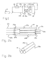
- Fig. 1 shows an apparatus for measuring a path length difference.
- the apparatus comprises a light source 10, a coupler 14, detectors 16a-c, a calculation unit 18 and a path length controller 19.
- Light from light source 10 is guided to a coupler 14 via two paths 12a,b.
- Light paths 12a,b each have their own path length, while the path lengths of the different light paths 12a,b can differ.
- Path length controller 19 is capable of adjusting the path length of one of the light paths under control. Further details of light paths 12a,b are not necessary to understand the invention and have therefore been omitted.
- Coupler 14 has three outputs which are each coupled to a respective detector 16a-c.
- Detectors 16a-c have outputs which are coupled to calculation unit 18.
- Calculation unit 18 has an output which is coupled to path length controller 19.
- Fig. 2a shows an example of a three-way coupler 14.
- This embodiment of three-way coupler 14 contains three optical wave guides 20a,b, 21 (for instance glass fibers) and incoupling lenses 22a,b. Light from the paths 12a,b is imaged on the inputs of two of the optical wave guides 20a,b by incoupling lenses 22a,b.
- the three optical wave guides 20a,b, 21 are set apart a short distance over at least a part of their lengths (this part is shown as a parallel running part).
- the three wave guides 20a,b, 21 are shown diagrammatically in a row in Fig. 2a, wave guides 20a,b, 21 abut each other in pairs as shown in Fig. 2b.
- the short distance between the wave guides 20a,b, 21 results in pairwise optical couplings, so that light waves partly couple from one wave guide to the other.
- light coupled in on one wave guide 20a,b, so distributed over the wave guides is coupled out on outputs 15a-c of the wave guides 20a,b, 21.
- the light on outputs forms combinations of the light waves coupled in on the inputs 20a,b, with the light, in each combination, being combined with different added phase differences.
- the phase displacement ⁇ is the same for the coupling between each pair of wave guides 20a,b, 21 (preferably one hundred and twenty degrees).
- the added phase difference between first light from first incoupling lens 22a and second light from second incoupling lens 22b will be - ⁇ on the output 15a where the first light arrives directly via a wave guide 20a and the second light arrives via a coupling, while the added phase difference is ⁇ on the output 15c where the first light arrives via a coupling and the second light directly via a wave guide 20b.
- the added phase difference will be zero on the output 15b of the wave guide 21 in which both the first and the second light arrive via a coupling.
- light from light source 10 is guided via two different light paths 12a,b to inputs of three-way coupler 14.
- the three-way coupler combines the light from the two light paths 12a,b in three different ways, whereby the light from the different light paths 12a,b is each time combined with a different relative phase: for instance on a first output 15a in phase, on a second output 15b with the light from the first light path 12a preferably leading the light from the second light path by one hundred and twenty degrees, and on a third output 15c with the light from the first light path 12a preferably lagging one hundred and twenty degrees behind the light from the second light path.
- the intensity of the combined light issuing from the different outputs 15a-c is detected by detectors 16a-c.
- Detectors 16a-c pass detection signals to calculation unit 18.
- the detection signals represent the detected intensities of the different combinations, for instance in the form of analogous electrical signals or in the form of digital representations of the measured intensity.
- Calculation unit 18 calculates the phase difference between the light from the different light paths 12a,b from the measured intensities.
- I0, I+ and I- are the intensities of the combinations of light from light paths 12a,b issuing on outputs 15a-c, where I0 represents the intensity of the combination with relative phase 0, and I+ and I- represent the combinations with phases leading and lagging 120 degrees.
- D is the path length difference between light paths 12a,b, and ⁇ is the wavelength of the light used.
- A is a function of the average amplitude of the light from the two light paths 12a,b and V is the contrast of the interference intensities. The contrast expresses, for instance, the difference between the amplitudes and/or polarization differences of the light from the two light paths 12a,b.
- calculation unit 18 determines a control difference with a desired path length difference and supplies a feedback signal to path length controller 19 which is proportional to the control difference.
- path length controller 19 which is proportional to the control difference.
- the calculation of the path length difference D according to the above formula is not unambiguous: the same measurement of I0, I+, I- can also correspond to a path length difference which differs a whole number of wavelengths ⁇ /2 from the given solution.
- the path length difference is originally between +/- a quarter of the wavelength ⁇ of the light used. If this cannot be assumed, then, in the above-described manner, a calculation is also made on measurements with light of a second wavelength ⁇ ' which differs from ⁇ .
- ⁇ ' which differs from ⁇ .
- a formula for the path length difference D can again be derived from this as a function of I0, I1, I2, from which the effect of A and V has been eliminated.
- the calculation unit can again calculate the path length difference D from the measured intensities I0, I1, I2.
- the calculation instead of being done with an explicit expression for D, can also be done by numerically solving D from the above equations, for instance by means of the Newton-Raphson algorithm known per se.
- Calculation unit 18 is preferably designed as a digital computer provided with a program to read out the measured intensities and to calculate D from the measurements of the intensities in the above-described manner.
- a program to read out the measured intensities and to calculate D from the measurements of the intensities in the above-described manner.
Landscapes
- Physics & Mathematics (AREA)
- General Physics & Mathematics (AREA)
- Engineering & Computer Science (AREA)
- Optics & Photonics (AREA)
- Signal Processing (AREA)
- Automation & Control Theory (AREA)
- Instruments For Measurement Of Length By Optical Means (AREA)
- Length Measuring Devices By Optical Means (AREA)
Claims (7)
- Appareil pour mesurer une différence de longueur de trajet optique, lequel appareil est muni- d'éléments optiques pour guider de la lumière depuis une source de lumière (10) à travers un premier et un second trajet,- d'un coupleur au moins à trois voies (14) pour combiner les lumières provenant des premier et second trajets l'une à l'autre selon au moins trois combinaisons avec au moins trois déplacements de phase relatifs ajoutés mutuellement différents,- un détecteur (16a-c) conçu pour mesurer des intensités d'interférence des au moins trois combinaisons,
caractérisé par- une unité de calcul (18) conçue pour déterminer, à partir des intensités, une différence de phase entre les lumières provenant des premier et second trajets tout en éliminant un effet d'un contraste entre les lumières provenant des premier et second trajets. - Appareil selon la revendication 1, dans lequel la différence de phase est déterminée de sorte qu'elle est cohérente avec les formules


- Appareil selon la revendication 1 ou 2, dans lequel le coupleur au moins à trois voies (14) combine les lumières provenant des premier et second trajets l'une à l'autre avec trois déplacements de phase relatifs différents ajoutés, qui diffèrent par paire virtuellement de 120 degrés.
- Appareil selon l'une quelconque des revendications précédentes, dans lequel le coupleur au moins à trois voies (14) comporte trois guides d'ondes mutuellement couplés.
- Appareil selon l'une quelconque des revendications précédentes, muni d'un contrôleur de longueur de trajet, dans lequel l'unité de calcul (18) est couplée à une entrée d'entraînement du contrôleur de longueur de trajet pour commander la différence de phase calculée par rétroaction à une différence de phase voulue.
- Procédé pour mesurer une différence de longueur de trajet optique, lequel procédé comporte les étapes consistant à :- guider la lumière depuis une source de lumière (10) à travers un premier et un second trajet,- combiner des lumières provenant des premier et second trajets selon au moins trois combinaisons avec au moins trois déplacements de phase relatifs ajoutés mutuellement différents,- mesurer des intensités d'interférence des au moins trois combinaisons,
caractérisé par- le calcul d'une différence de phase entre les lumières provenant des premier et second trajets tout en éliminant un effet d'un contraste entre la lumière provenant des premier et second trajets. - Produit de programme informatique ayant des instructions pour qu'un ordinateur effectue les étapes suivantes consistant à :- échantillonner des intensités d'interférence d'au moins trois combinaisons de lumière provenant d'un premier et d'un second trajet de lumière, dans lequel la lumière dans les trois combinaisons est combinée à au moins trois déplacements de phase relatifs ajoutés mutuellement différents,
caractérisé par- le calcul d'une différence de phase entre les lumières provenant des premier et second trajets tout en éliminant un effet d'un contraste entre les lumières provenant des premier et second trajets.
Applications Claiming Priority (3)
| Application Number | Priority Date | Filing Date | Title |
|---|---|---|---|
| NL1021600A NL1021600C2 (nl) | 2002-10-08 | 2002-10-08 | Meten van een optisch weglengteverschil. |
| NL1021600 | 2002-10-08 | ||
| PCT/NL2003/000683 WO2004033987A1 (fr) | 2002-10-08 | 2003-10-08 | Dispositif pour mesurer une difference de longueur de chemin optique |
Publications (2)
| Publication Number | Publication Date |
|---|---|
| EP1549904A1 EP1549904A1 (fr) | 2005-07-06 |
| EP1549904B1 true EP1549904B1 (fr) | 2007-04-25 |
Family
ID=32089840
Family Applications (1)
| Application Number | Title | Priority Date | Filing Date |
|---|---|---|---|
| EP03754308A Expired - Lifetime EP1549904B1 (fr) | 2002-10-08 | 2003-10-08 | Dispositif pour mesurer une difference de longueur de chemin optique |
Country Status (7)
| Country | Link |
|---|---|
| US (1) | US7369248B2 (fr) |
| EP (1) | EP1549904B1 (fr) |
| AT (1) | ATE360798T1 (fr) |
| AU (1) | AU2003272146A1 (fr) |
| DE (1) | DE60313479T2 (fr) |
| NL (1) | NL1021600C2 (fr) |
| WO (1) | WO2004033987A1 (fr) |
Cited By (1)
| Publication number | Priority date | Publication date | Assignee | Title |
|---|---|---|---|---|
| WO2011126372A1 (fr) | 2010-04-09 | 2011-10-13 | Nederlandse Organisatie Voor Toegepast-Natuurwetenschappelijk Onderzoek Tno | Système à longueur d'onde de balayage et procédé d'étalonnage de tel système |
Families Citing this family (7)
| Publication number | Priority date | Publication date | Assignee | Title |
|---|---|---|---|---|
| US7206069B2 (en) * | 2004-03-29 | 2007-04-17 | Lucent Technologies Inc. | Optical analyzers of polarization properties |
| EP2236978B8 (fr) | 2009-04-01 | 2013-12-04 | Nederlandse Organisatie voor toegepast -natuurwetenschappelijk onderzoek TNO | Dispositif de mesure optique et procédé pour déterminer la forme d'un objet et machine pour former l'objet |
| GB2474882B (en) * | 2009-10-29 | 2014-04-09 | Tgs Geophysical Company Uk Ltd | Signal processing |
| EP2469255A1 (fr) | 2010-12-22 | 2012-06-27 | Nederlandse Organisatie voor toegepast -natuurwetenschappelijk onderzoek TNO | Dispositif de mesure optique |
| EP2792996A1 (fr) | 2013-04-17 | 2014-10-22 | Nederlandse Organisatie voor toegepast -natuurwetenschappelijk onderzoek TNO | Dispositif de détection de distance interférométrique et procédé |
| EP3614098A1 (fr) | 2018-08-24 | 2020-02-26 | Nederlandse Organisatie voor toegepast- natuurwetenschappelijk onderzoek TNO | Dispositif et procédé de mesure interférométrique d'une traduction bidimensionnelle ou tridimensionnelle d'un objet |
| EP4067838A1 (fr) * | 2021-03-31 | 2022-10-05 | Nederlandse Organisatie voor toegepast- natuurwetenschappelijk onderzoek TNO | Procédé et système pour déterminer un déphasage entre les composantes d'une lumière amplifiée de façon variable |
Family Cites Families (6)
| Publication number | Priority date | Publication date | Assignee | Title |
|---|---|---|---|---|
| US4818109A (en) * | 1985-06-28 | 1989-04-04 | Litton Systems, Inc. | Fiber optical combiner particularly for a ring laser gyro |
| US4728191A (en) * | 1986-10-22 | 1988-03-01 | Optical Technologies, Incorporated | Divided interferometer employing a single 3×3 coupler/splitter |
| US4923268A (en) * | 1987-09-14 | 1990-05-08 | Aster Corporation | Fiber optic coupler |
| US5777737A (en) * | 1994-07-22 | 1998-07-07 | Litton Systems, Inc. | Apparatus and method for processing signals output from fiber optic rate gyroscope having 3×3 coupler |
| EP0808448A1 (fr) * | 1995-12-08 | 1997-11-26 | Litton Systems, Inc. | Configuration optimale de coupleur 3 x 3 pour gyroscope a fibre optique |
| US6886404B2 (en) * | 2003-02-05 | 2005-05-03 | Fibersonde Corporation | Fiber optic accelerometer |
-
2002
- 2002-10-08 NL NL1021600A patent/NL1021600C2/nl not_active IP Right Cessation
-
2003
- 2003-10-08 WO PCT/NL2003/000683 patent/WO2004033987A1/fr not_active Ceased
- 2003-10-08 DE DE60313479T patent/DE60313479T2/de not_active Expired - Lifetime
- 2003-10-08 AU AU2003272146A patent/AU2003272146A1/en not_active Abandoned
- 2003-10-08 US US10/530,916 patent/US7369248B2/en not_active Expired - Lifetime
- 2003-10-08 AT AT03754308T patent/ATE360798T1/de not_active IP Right Cessation
- 2003-10-08 EP EP03754308A patent/EP1549904B1/fr not_active Expired - Lifetime
Cited By (1)
| Publication number | Priority date | Publication date | Assignee | Title |
|---|---|---|---|---|
| WO2011126372A1 (fr) | 2010-04-09 | 2011-10-13 | Nederlandse Organisatie Voor Toegepast-Natuurwetenschappelijk Onderzoek Tno | Système à longueur d'onde de balayage et procédé d'étalonnage de tel système |
Also Published As
| Publication number | Publication date |
|---|---|
| US7369248B2 (en) | 2008-05-06 |
| US20050275846A1 (en) | 2005-12-15 |
| WO2004033987A1 (fr) | 2004-04-22 |
| EP1549904A1 (fr) | 2005-07-06 |
| NL1021600C2 (nl) | 2004-04-13 |
| DE60313479D1 (de) | 2007-06-06 |
| DE60313479T2 (de) | 2008-01-03 |
| ATE360798T1 (de) | 2007-05-15 |
| AU2003272146A1 (en) | 2004-05-04 |
Similar Documents
| Publication | Publication Date | Title |
|---|---|---|
| US5288995A (en) | Electrical measurement apparatus using heterodyne phase conversion techniques | |
| EP0646767A2 (fr) | Dispositif de mesure de distance par interférométrie | |
| US20080013095A1 (en) | Fiber optic interferometric position sensor and measurement method thereof | |
| US4776698A (en) | Measuring | |
| WO2013082247A1 (fr) | Interféromètre, système et procédé d'utilisation | |
| CN118209049A (zh) | 一种基于三光束干涉的光纤位移测量系统及方法 | |
| JPS6343716B2 (fr) | ||
| JPH07500909A (ja) | 計測装置 | |
| CN111751610A (zh) | 实现非互易动态相位调制的光纤电流传感器及相应的信号解调方法 | |
| EP2986929B1 (fr) | Dispositif de détection de distance interférométrique et procédé | |
| US7369248B2 (en) | Device for measuring an optical path length difference | |
| US4566794A (en) | Apparatus for interference fringe shift sensing | |
| US20140300900A1 (en) | Optical fiber sensor | |
| US5179424A (en) | Optoelectronic apparatus for the remote measuring of a physical magnitude | |
| GB2046434A (en) | Optical-fibre interferometric gyrometer | |
| JPS6356924B2 (fr) | ||
| KR100431706B1 (ko) | 2 주파수 레이저 간섭계에서의 길이 측정을 위한 위상각측정방법 및 비선형 오차 보상방법 그리고 이를 이용한길이 측정을 위한 위상각 측정방법 및 측정 시스템 | |
| JP3687971B2 (ja) | 干渉計式光ファイバージャイロにおける残留複屈折を補償する方法及び装置 | |
| CN115900535B (zh) | 干涉解调装置和干涉测量系统 | |
| EP0556960A2 (fr) | Appareil de mesure utilisant les techniques de conversion de phase hétérodyne | |
| EP0307451A1 (fr) | Appareil et procede de localisation de la direction d'un faisceau atomique. | |
| JPS6227603A (ja) | 変位の光学的測定装置 | |
| RU2791671C1 (ru) | Волоконно-оптический датчик угловой скорости и способ измерения угловой скорости | |
| SU569849A1 (ru) | Устройство дл измерени углов скручивани | |
| JPS60213815A (ja) | 光干渉角速度計 |
Legal Events
| Date | Code | Title | Description |
|---|---|---|---|
| PUAI | Public reference made under article 153(3) epc to a published international application that has entered the european phase |
Free format text: ORIGINAL CODE: 0009012 |
|
| 17P | Request for examination filed |
Effective date: 20050408 |
|
| AK | Designated contracting states |
Kind code of ref document: A1 Designated state(s): AT BE BG CH CY CZ DE DK EE ES FI FR GB GR HU IE IT LI LU MC NL PT RO SE SI SK TR |
|
| AX | Request for extension of the european patent |
Extension state: AL LT LV MK |
|
| DAX | Request for extension of the european patent (deleted) | ||
| 17Q | First examination report despatched |
Effective date: 20060705 |
|
| GRAP | Despatch of communication of intention to grant a patent |
Free format text: ORIGINAL CODE: EPIDOSNIGR1 |
|
| GRAS | Grant fee paid |
Free format text: ORIGINAL CODE: EPIDOSNIGR3 |
|
| GRAA | (expected) grant |
Free format text: ORIGINAL CODE: 0009210 |
|
| AK | Designated contracting states |
Kind code of ref document: B1 Designated state(s): AT BE BG CH CY CZ DE DK EE ES FI FR GB GR HU IE IT LI LU MC NL PT RO SE SI SK TR |
|
| PG25 | Lapsed in a contracting state [announced via postgrant information from national office to epo] |
Ref country code: LI Free format text: LAPSE BECAUSE OF FAILURE TO SUBMIT A TRANSLATION OF THE DESCRIPTION OR TO PAY THE FEE WITHIN THE PRESCRIBED TIME-LIMIT Effective date: 20070425 Ref country code: CH Free format text: LAPSE BECAUSE OF FAILURE TO SUBMIT A TRANSLATION OF THE DESCRIPTION OR TO PAY THE FEE WITHIN THE PRESCRIBED TIME-LIMIT Effective date: 20070425 Ref country code: FI Free format text: LAPSE BECAUSE OF FAILURE TO SUBMIT A TRANSLATION OF THE DESCRIPTION OR TO PAY THE FEE WITHIN THE PRESCRIBED TIME-LIMIT Effective date: 20070425 |
|
| REG | Reference to a national code |
Ref country code: GB Ref legal event code: FG4D |
|
| REG | Reference to a national code |
Ref country code: IE Ref legal event code: FG4D |
|
| REG | Reference to a national code |
Ref country code: CH Ref legal event code: EP |
|
| REF | Corresponds to: |
Ref document number: 60313479 Country of ref document: DE Date of ref document: 20070606 Kind code of ref document: P |
|
| PG25 | Lapsed in a contracting state [announced via postgrant information from national office to epo] |
Ref country code: SE Free format text: LAPSE BECAUSE OF FAILURE TO SUBMIT A TRANSLATION OF THE DESCRIPTION OR TO PAY THE FEE WITHIN THE PRESCRIBED TIME-LIMIT Effective date: 20070725 |
|
| PG25 | Lapsed in a contracting state [announced via postgrant information from national office to epo] |
Ref country code: ES Free format text: LAPSE BECAUSE OF FAILURE TO SUBMIT A TRANSLATION OF THE DESCRIPTION OR TO PAY THE FEE WITHIN THE PRESCRIBED TIME-LIMIT Effective date: 20070805 |
|
| PG25 | Lapsed in a contracting state [announced via postgrant information from national office to epo] |
Ref country code: PT Free format text: LAPSE BECAUSE OF FAILURE TO SUBMIT A TRANSLATION OF THE DESCRIPTION OR TO PAY THE FEE WITHIN THE PRESCRIBED TIME-LIMIT Effective date: 20070925 |
|
| ET | Fr: translation filed | ||
| REG | Reference to a national code |
Ref country code: CH Ref legal event code: PL |
|
| PG25 | Lapsed in a contracting state [announced via postgrant information from national office to epo] |
Ref country code: AT Free format text: LAPSE BECAUSE OF FAILURE TO SUBMIT A TRANSLATION OF THE DESCRIPTION OR TO PAY THE FEE WITHIN THE PRESCRIBED TIME-LIMIT Effective date: 20070425 |
|
| PG25 | Lapsed in a contracting state [announced via postgrant information from national office to epo] |
Ref country code: BE Free format text: LAPSE BECAUSE OF FAILURE TO SUBMIT A TRANSLATION OF THE DESCRIPTION OR TO PAY THE FEE WITHIN THE PRESCRIBED TIME-LIMIT Effective date: 20070425 |
|
| PG25 | Lapsed in a contracting state [announced via postgrant information from national office to epo] |
Ref country code: DK Free format text: LAPSE BECAUSE OF FAILURE TO SUBMIT A TRANSLATION OF THE DESCRIPTION OR TO PAY THE FEE WITHIN THE PRESCRIBED TIME-LIMIT Effective date: 20070425 Ref country code: BG Free format text: LAPSE BECAUSE OF FAILURE TO SUBMIT A TRANSLATION OF THE DESCRIPTION OR TO PAY THE FEE WITHIN THE PRESCRIBED TIME-LIMIT Effective date: 20070725 Ref country code: SI Free format text: LAPSE BECAUSE OF FAILURE TO SUBMIT A TRANSLATION OF THE DESCRIPTION OR TO PAY THE FEE WITHIN THE PRESCRIBED TIME-LIMIT Effective date: 20070425 Ref country code: CZ Free format text: LAPSE BECAUSE OF FAILURE TO SUBMIT A TRANSLATION OF THE DESCRIPTION OR TO PAY THE FEE WITHIN THE PRESCRIBED TIME-LIMIT Effective date: 20070425 |
|
| PG25 | Lapsed in a contracting state [announced via postgrant information from national office to epo] |
Ref country code: SK Free format text: LAPSE BECAUSE OF FAILURE TO SUBMIT A TRANSLATION OF THE DESCRIPTION OR TO PAY THE FEE WITHIN THE PRESCRIBED TIME-LIMIT Effective date: 20070425 |
|
| PLBE | No opposition filed within time limit |
Free format text: ORIGINAL CODE: 0009261 |
|
| STAA | Information on the status of an ep patent application or granted ep patent |
Free format text: STATUS: NO OPPOSITION FILED WITHIN TIME LIMIT |
|
| 26N | No opposition filed |
Effective date: 20080128 |
|
| PG25 | Lapsed in a contracting state [announced via postgrant information from national office to epo] |
Ref country code: GR Free format text: LAPSE BECAUSE OF FAILURE TO SUBMIT A TRANSLATION OF THE DESCRIPTION OR TO PAY THE FEE WITHIN THE PRESCRIBED TIME-LIMIT Effective date: 20070726 |
|
| PG25 | Lapsed in a contracting state [announced via postgrant information from national office to epo] |
Ref country code: RO Free format text: LAPSE BECAUSE OF FAILURE TO SUBMIT A TRANSLATION OF THE DESCRIPTION OR TO PAY THE FEE WITHIN THE PRESCRIBED TIME-LIMIT Effective date: 20070425 Ref country code: MC Free format text: LAPSE BECAUSE OF NON-PAYMENT OF DUE FEES Effective date: 20071031 |
|
| PG25 | Lapsed in a contracting state [announced via postgrant information from national office to epo] |
Ref country code: IE Free format text: LAPSE BECAUSE OF NON-PAYMENT OF DUE FEES Effective date: 20071008 |
|
| PG25 | Lapsed in a contracting state [announced via postgrant information from national office to epo] |
Ref country code: EE Free format text: LAPSE BECAUSE OF FAILURE TO SUBMIT A TRANSLATION OF THE DESCRIPTION OR TO PAY THE FEE WITHIN THE PRESCRIBED TIME-LIMIT Effective date: 20070425 |
|
| PG25 | Lapsed in a contracting state [announced via postgrant information from national office to epo] |
Ref country code: CY Free format text: LAPSE BECAUSE OF FAILURE TO SUBMIT A TRANSLATION OF THE DESCRIPTION OR TO PAY THE FEE WITHIN THE PRESCRIBED TIME-LIMIT Effective date: 20070425 |
|
| PG25 | Lapsed in a contracting state [announced via postgrant information from national office to epo] |
Ref country code: LU Free format text: LAPSE BECAUSE OF NON-PAYMENT OF DUE FEES Effective date: 20071008 |
|
| PG25 | Lapsed in a contracting state [announced via postgrant information from national office to epo] |
Ref country code: HU Free format text: LAPSE BECAUSE OF FAILURE TO SUBMIT A TRANSLATION OF THE DESCRIPTION OR TO PAY THE FEE WITHIN THE PRESCRIBED TIME-LIMIT Effective date: 20071026 Ref country code: TR Free format text: LAPSE BECAUSE OF FAILURE TO SUBMIT A TRANSLATION OF THE DESCRIPTION OR TO PAY THE FEE WITHIN THE PRESCRIBED TIME-LIMIT Effective date: 20070425 |
|
| REG | Reference to a national code |
Ref country code: FR Ref legal event code: PLFP Year of fee payment: 13 |
|
| REG | Reference to a national code |
Ref country code: FR Ref legal event code: PLFP Year of fee payment: 14 |
|
| REG | Reference to a national code |
Ref country code: FR Ref legal event code: PLFP Year of fee payment: 15 |
|
| REG | Reference to a national code |
Ref country code: FR Ref legal event code: PLFP Year of fee payment: 16 |
|
| PGFP | Annual fee paid to national office [announced via postgrant information from national office to epo] |
Ref country code: NL Payment date: 20201028 Year of fee payment: 18 |
|
| PGFP | Annual fee paid to national office [announced via postgrant information from national office to epo] |
Ref country code: GB Payment date: 20201022 Year of fee payment: 18 Ref country code: FR Payment date: 20201021 Year of fee payment: 18 Ref country code: IT Payment date: 20201026 Year of fee payment: 18 Ref country code: DE Payment date: 20201022 Year of fee payment: 18 |
|
| REG | Reference to a national code |
Ref country code: DE Ref legal event code: R119 Ref document number: 60313479 Country of ref document: DE |
|
| REG | Reference to a national code |
Ref country code: NL Ref legal event code: MM Effective date: 20211101 |
|
| GBPC | Gb: european patent ceased through non-payment of renewal fee |
Effective date: 20211008 |
|
| PG25 | Lapsed in a contracting state [announced via postgrant information from national office to epo] |
Ref country code: NL Free format text: LAPSE BECAUSE OF NON-PAYMENT OF DUE FEES Effective date: 20211101 Ref country code: GB Free format text: LAPSE BECAUSE OF NON-PAYMENT OF DUE FEES Effective date: 20211008 Ref country code: DE Free format text: LAPSE BECAUSE OF NON-PAYMENT OF DUE FEES Effective date: 20220503 |
|
| PG25 | Lapsed in a contracting state [announced via postgrant information from national office to epo] |
Ref country code: FR Free format text: LAPSE BECAUSE OF NON-PAYMENT OF DUE FEES Effective date: 20211031 |
|
| PG25 | Lapsed in a contracting state [announced via postgrant information from national office to epo] |
Ref country code: IT Free format text: LAPSE BECAUSE OF NON-PAYMENT OF DUE FEES Effective date: 20211008 |