EP1550532A1 - Outil manuel avec amortissement de vibrations - Google Patents
Outil manuel avec amortissement de vibrations Download PDFInfo
- Publication number
- EP1550532A1 EP1550532A1 EP04105721A EP04105721A EP1550532A1 EP 1550532 A1 EP1550532 A1 EP 1550532A1 EP 04105721 A EP04105721 A EP 04105721A EP 04105721 A EP04105721 A EP 04105721A EP 1550532 A1 EP1550532 A1 EP 1550532A1
- Authority
- EP
- European Patent Office
- Prior art keywords
- vibration damping
- drive
- hand tool
- unit
- housing
- Prior art date
- Legal status (The legal status is an assumption and is not a legal conclusion. Google has not performed a legal analysis and makes no representation as to the accuracy of the status listed.)
- Granted
Links
- 238000013016 damping Methods 0.000 title claims abstract 17
- 230000008878 coupling Effects 0.000 claims abstract 2
- 238000010168 coupling process Methods 0.000 claims abstract 2
- 238000005859 coupling reaction Methods 0.000 claims abstract 2
- 230000005540 biological transmission Effects 0.000 claims 1
- 230000010355 oscillation Effects 0.000 abstract 1
- 230000002093 peripheral effect Effects 0.000 abstract 1
Images
Classifications
-
- B—PERFORMING OPERATIONS; TRANSPORTING
- B25—HAND TOOLS; PORTABLE POWER-DRIVEN TOOLS; MANIPULATORS
- B25F—COMBINATION OR MULTI-PURPOSE TOOLS NOT OTHERWISE PROVIDED FOR; DETAILS OR COMPONENTS OF PORTABLE POWER-DRIVEN TOOLS NOT PARTICULARLY RELATED TO THE OPERATIONS PERFORMED AND NOT OTHERWISE PROVIDED FOR
- B25F5/00—Details or components of portable power-driven tools not particularly related to the operations performed and not otherwise provided for
- B25F5/006—Vibration damping means
Definitions
- the invention is based on a hand tool the preamble of claim 1.
- From DE 40 00 861 C2 is a hand tool with a Motor housing known on the one tool holder opposite side of the hammer drill from a shell is surrounded.
- a handle with a Handle element molded.
- the casing is over a Vibration damping device connected to the motor housing, at the same time a support element for the handle forms.
- the vibration damping device has a plurality of elastic Rubber vibration damping units, over the shell, and thus the handle, from the motor housing vibrationally decoupled.
- the invention relates to a hand tool with a Housing, are arranged in the drive units, wherein in the housing at least one vibration damping device is provided.
- a drive arrangement with at least a drive unit by the vibration damping device relative to the housing in the axial, radial and circumferential direction is decoupled. Any device vibrations can be intercepted in all three directions of vibration. At the same time there is the possibility of an offset of central axes to compensate for drive units in the drive assembly. Both mode of action and handling of the Hand tool remain unaffected.
- the drive assembly along a longitudinal extent at least one drive motor and / or a transmission and / or a coupling and / or a tool drive, suitable Vibration damping units for damping of the different drive units specific vibration directions purposefully placed on different drive units become.
- a possible offset of central axes the drive units in a rigid drive assembly are summarized, cost-effectively balanced be there on additional compensation elements or one elaborate and expensive interior contour in the housing are dispensed with can.
- the vibration damping device a first vibration damping unit for Damping at least axially directed vibrations, wherein Preferably, the first vibration damping unit on a Front side of a front end of the drive assembly arranged drive motor is provided.
- the first vibration damping unit on a Front side of a front end of the drive assembly arranged drive motor is provided.
- the Drive arrangement can be stored in the axial direction and simultaneously vibration energy in the axial direction of the housing be kept away.
- the first vibration damping unit a possible offset of the central axes the drive units axially, i. in the longitudinal direction, compensate.
- the second vibration damping unit may be the drive arrangement also support in the radial direction.
- the Vibration damping unit is preferably a rubber element or alternatively, a compression spring, a helical compression spring or an element which appears reasonable to the person skilled in the art be.
- the vibration damping device comprises a second vibration damping unit for Attenuation of at least radially directed vibrations, being preferred the second vibration damping unit peripherally is arranged around a transmission of the drive assembly.
- the second Vibration damping unit a possible radial offset compensate for the center axes of the drive units.
- a third vibration damping unit for damping Vibrations comprises at least in the circumferential direction, wherein the third vibration damping unit in the region of a clutch the drive arrangement is provided.
- This can be vibrations the drive assembly in the circumferential direction of the housing be kept away.
- the third vibration damping unit can simultaneously a possible angular offset of the central axes compensate the drive units.
- the third vibration damping unit can the drive assembly in the radial Support the direction.
- the vibration damping units are made of one soft, rubbery material formed.
- vibration absorbing materials such as Composite bodies, springs and the like.
- the invention can be independent on the nature of the connection of the housing parts with each other be used.
- the drive arrangement forms a substantially rigid unit, can with a suitable distribution of the vibration damping units the vibration damping device a advantageous storage of the drive assembly exclusively be realized by the vibration damping device.
- the drive assembly can thereby practically completely from be decoupled from the housing.
- the drive assembly is located only via the vibration damping device on the housing. Good handling and operation of the Hand tool remains.
- the solution according to the invention can be carried out by various persons skilled in the art applied as meaningful machine tools be, but particularly advantageous in electrically driven Hand tool machines, such as impact drills, Scrapers, saws, screwdrivers and in particular angle grinders etc., due to their mostly free mobility and often high drive speeds in principle too Tend to oscillate. Very favorable is the use in such Hand tool machines, where no additional handle or no extra hold outside the area the enveloping geometry are provided, but their Housing itself represents a handle, such as with hand-held screwdrivers, industrial screwdrivers with controlled shutdown and the like.
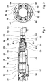
- a longitudinal section through a part of a preferred Screwdriver trained hand tool 10 shows figure 1.
- a housing 12 encloses a drive assembly 14 which a trained as a motor first drive unit 16, a designed as a transmission second drive unit 18, as Clutch, in particular Automatrastkupplung trained third Drive unit 20 and designed as a tool drive fourth drive unit 22 has.
- the drive units 16, 18, 20, 22 are along a longitudinal extent 52 of the drive assembly 14 arranged.
- the drive units 16, 18, 20, 22 have central axes 24, 26, 28, 30, which in the ideal case form a common central axis, but also, for example production-related, offset against each other can.
- a shaft 56 extends from the transmission formed second drive unit 18 for as a tool drive formed fourth drive unit 22.
- the drive units 16, 18, 20, 22 of the drive assembly 14 are substantially rigidly coupled with each other.
- a first, for damping at least axially directed vibrations provided vibration damping unit 32 is at a End face 38 of the drive motor designed as the first Drive unit 16 is arranged.
- a second, for damping at least radially directed vibrations provided vibration damping unit 34 is circumferentially on a circumference 40th around the second drive unit 18 designed as a transmission arranged.
- a third, for damping at least in the circumferential direction acting vibrations provided vibration damping unit 36 is formed in the region of the coupling provided third drive unit 20 and surrounds there Pin 42.
- the individual vibration damping units 32, 34, 36 are part of a vibration damping device.
- Figure 2 shows a cross section through an area with a in the tangential direction damping third vibration damping unit 36. Substantially equal parts basically numbered with the same reference numerals. Further can with regard to consistent features and functions Reference is made to the description of Figure 1.
- Two enclosing housing 12 forming housing halves 64, 66 are in a first bore 44 with a screw 48 and in a second bore 46 with a screw 50 together connected.
- a sleeve 62 formed as a coupling third drive unit 20 ( Figure 2) is on both sides of a Spigot 42 in the lower housing half 66 and a pin 68 arranged in the upper housing half 64. In the Center is an opening through which a shaft is passed can. Both pins 42, 68 are each a vibration damping unit 36 surrounded.
Landscapes
- Engineering & Computer Science (AREA)
- Mechanical Engineering (AREA)
- Portable Power Tools In General (AREA)
- Auxiliary Devices For Machine Tools (AREA)
- Connection Of Motors, Electrical Generators, Mechanical Devices, And The Like (AREA)
- Percussive Tools And Related Accessories (AREA)
Applications Claiming Priority (2)
| Application Number | Priority Date | Filing Date | Title |
|---|---|---|---|
| DE2003161812 DE10361812A1 (de) | 2003-12-30 | 2003-12-30 | Handwerkzeugmaschine |
| DE10361812 | 2003-12-30 |
Publications (2)
| Publication Number | Publication Date |
|---|---|
| EP1550532A1 true EP1550532A1 (fr) | 2005-07-06 |
| EP1550532B1 EP1550532B1 (fr) | 2008-10-08 |
Family
ID=34559789
Family Applications (1)
| Application Number | Title | Priority Date | Filing Date |
|---|---|---|---|
| EP20040105721 Expired - Lifetime EP1550532B1 (fr) | 2003-12-30 | 2004-11-12 | Outil manuel avec amortissement de vibrations |
Country Status (3)
| Country | Link |
|---|---|
| EP (1) | EP1550532B1 (fr) |
| CN (1) | CN100457400C (fr) |
| DE (2) | DE10361812A1 (fr) |
Cited By (4)
| Publication number | Priority date | Publication date | Assignee | Title |
|---|---|---|---|---|
| WO2008006635A1 (fr) * | 2006-07-10 | 2008-01-17 | Robert Bosch Gmbh | Machine-outil à main |
| JP2011036924A (ja) * | 2009-08-06 | 2011-02-24 | Makita Corp | 電動工具 |
| CN105666393A (zh) * | 2015-12-31 | 2016-06-15 | 宁波中旺工具有限公司 | 一种电动螺丝刀 |
| EP2841237B2 (fr) † | 2012-04-24 | 2024-07-10 | C. & E. Fein GmbH | Machine-outil pouvant être guidée manuellement et comportant un carter |
Families Citing this family (5)
| Publication number | Priority date | Publication date | Assignee | Title |
|---|---|---|---|---|
| DE102008001268A1 (de) * | 2008-04-18 | 2009-10-22 | Robert Bosch Gmbh | Steckeranordnung in einer Werkzeugmaschine, insbesondere in einer Handwerkzeugmaschine |
| AU2010263293B2 (en) * | 2009-06-25 | 2015-11-26 | Atlas Copco Airpower, Naamloze Venootschap | Hand-held demolition tool |
| SE540933C2 (en) | 2016-12-29 | 2018-12-27 | Husqvarna Ab | Improved handheld power tool |
| CN209408417U (zh) * | 2018-06-05 | 2019-09-20 | 南京德朔实业有限公司 | 动力工具 |
| DE102023209854A1 (de) * | 2023-10-10 | 2025-04-10 | Robert Bosch Gesellschaft mit beschränkter Haftung | Hubsägenvorrichtung und Hubsäge |
Citations (5)
| Publication number | Priority date | Publication date | Assignee | Title |
|---|---|---|---|---|
| GB2154497A (en) * | 1984-02-18 | 1985-09-11 | Bosch Gmbh Robert | Hand machine tool, particularly hammer drill or percussion drill |
| US5322131A (en) * | 1993-05-20 | 1994-06-21 | Chicago Pneumatic Tool Company | Vibration-reduced pneumatic tool |
| US6286610B1 (en) * | 1997-07-15 | 2001-09-11 | Wacker-Werke Gmbh & Co. Kg | Percussion and/or drill hammer with oscillation damping |
| US6318479B1 (en) * | 1999-10-01 | 2001-11-20 | Chicago Pneumatic Tool Company | Vibration isolated impact wrench |
| US20030006051A1 (en) * | 2001-06-21 | 2003-01-09 | Harald Schmitzer | Percussion electrical hand-held power tool with active vibration damping |
Family Cites Families (2)
| Publication number | Priority date | Publication date | Assignee | Title |
|---|---|---|---|---|
| CN2138694Y (zh) * | 1991-11-11 | 1993-07-21 | 西安石油学院 | 矿场随钻主动减震器 |
| JP4157382B2 (ja) * | 2001-04-11 | 2008-10-01 | ローベルト ボツシユ ゲゼルシヤフト ミツト ベシユレンクテル ハフツング | 振動減衰式のハンドグリップを備えた手持ち工作機械 |
-
2003
- 2003-12-30 DE DE2003161812 patent/DE10361812A1/de not_active Withdrawn
-
2004
- 2004-11-12 DE DE200450008196 patent/DE502004008196D1/de not_active Expired - Lifetime
- 2004-11-12 EP EP20040105721 patent/EP1550532B1/fr not_active Expired - Lifetime
- 2004-12-29 CN CNB2004101048292A patent/CN100457400C/zh not_active Expired - Fee Related
Patent Citations (5)
| Publication number | Priority date | Publication date | Assignee | Title |
|---|---|---|---|---|
| GB2154497A (en) * | 1984-02-18 | 1985-09-11 | Bosch Gmbh Robert | Hand machine tool, particularly hammer drill or percussion drill |
| US5322131A (en) * | 1993-05-20 | 1994-06-21 | Chicago Pneumatic Tool Company | Vibration-reduced pneumatic tool |
| US6286610B1 (en) * | 1997-07-15 | 2001-09-11 | Wacker-Werke Gmbh & Co. Kg | Percussion and/or drill hammer with oscillation damping |
| US6318479B1 (en) * | 1999-10-01 | 2001-11-20 | Chicago Pneumatic Tool Company | Vibration isolated impact wrench |
| US20030006051A1 (en) * | 2001-06-21 | 2003-01-09 | Harald Schmitzer | Percussion electrical hand-held power tool with active vibration damping |
Cited By (6)
| Publication number | Priority date | Publication date | Assignee | Title |
|---|---|---|---|---|
| WO2008006635A1 (fr) * | 2006-07-10 | 2008-01-17 | Robert Bosch Gmbh | Machine-outil à main |
| JP2011036924A (ja) * | 2009-08-06 | 2011-02-24 | Makita Corp | 電動工具 |
| EP2281663A3 (fr) * | 2009-08-06 | 2011-07-13 | Makita Corporation | Outils électriques |
| US8413743B2 (en) | 2009-08-06 | 2013-04-09 | Makita Corporation | Power tools |
| EP2841237B2 (fr) † | 2012-04-24 | 2024-07-10 | C. & E. Fein GmbH | Machine-outil pouvant être guidée manuellement et comportant un carter |
| CN105666393A (zh) * | 2015-12-31 | 2016-06-15 | 宁波中旺工具有限公司 | 一种电动螺丝刀 |
Also Published As
| Publication number | Publication date |
|---|---|
| CN1636681A (zh) | 2005-07-13 |
| DE10361812A1 (de) | 2005-07-28 |
| EP1550532B1 (fr) | 2008-10-08 |
| CN100457400C (zh) | 2009-02-04 |
| DE502004008196D1 (de) | 2008-11-20 |
Similar Documents
| Publication | Publication Date | Title |
|---|---|---|
| EP1940593B1 (fr) | Machine-outil electrique | |
| EP1965952B1 (fr) | Machine-outil a main pourvue d'un ensemble transmission et d'une unite de decouplage | |
| EP1335815B1 (fr) | Poignee de machine portable | |
| EP2512752B1 (fr) | Machine-outil portative | |
| EP1800805B1 (fr) | Poignée d'un outil à main | |
| EP2160272A1 (fr) | Unité de boîtier pour des machines-outils manuelles | |
| DE102007037047A1 (de) | Zusatzhandgriffvorrichtung | |
| DE102009028622A1 (de) | Handwerkzeugmaschinenschalteinheit | |
| DE102017211779A1 (de) | Handwerkzeugmaschinenvorrichtung | |
| EP1550532B1 (fr) | Outil manuel avec amortissement de vibrations | |
| WO2008006635A1 (fr) | Machine-outil à main | |
| DE3922552A1 (de) | Handgefuehrtes elektrowerkzeug | |
| DE102017211772A1 (de) | Handwerkzeugmaschinenvorrichtung | |
| DE102005000199A1 (de) | Handwerkzeuggerät mit Ratschenschlagwerk | |
| EP1752259B1 (fr) | Outil électrique | |
| WO2018011206A1 (fr) | Système de machine-outil portative | |
| DE202016103701U1 (de) | Handwerkzeugmaschinenvorrichtung | |
| DE102012222639A1 (de) | Handwerkzeugmaschinenschlagwerkvorrichtung | |
| DE10348973A1 (de) | Vibrationsgedämpfter Handgriff | |
| DE19652751A1 (de) | Handwerkzeugmaschine | |
| EP3274132B1 (fr) | Machine-outil portative | |
| WO2013131677A1 (fr) | Dispositif de machine-outil portative | |
| DE10348974A1 (de) | Vibrationsgedämpfter Handgriff | |
| DE102017211773A1 (de) | Handwerkzeugmaschinenvorrichtung | |
| DE2912718A1 (de) | Durch druckluft angetriebenes werkzeug |
Legal Events
| Date | Code | Title | Description |
|---|---|---|---|
| PUAI | Public reference made under article 153(3) epc to a published international application that has entered the european phase |
Free format text: ORIGINAL CODE: 0009012 |
|
| AK | Designated contracting states |
Kind code of ref document: A1 Designated state(s): AT BE BG CH CY CZ DE DK EE ES FI FR GB GR HU IE IS IT LI LU MC NL PL PT RO SE SI SK TR |
|
| AX | Request for extension of the european patent |
Extension state: AL HR LT LV MK YU |
|
| 17P | Request for examination filed |
Effective date: 20060109 |
|
| AKX | Designation fees paid |
Designated state(s): DE FR GB SE |
|
| 17Q | First examination report despatched |
Effective date: 20060406 |
|
| GRAP | Despatch of communication of intention to grant a patent |
Free format text: ORIGINAL CODE: EPIDOSNIGR1 |
|
| GRAS | Grant fee paid |
Free format text: ORIGINAL CODE: EPIDOSNIGR3 |
|
| GRAA | (expected) grant |
Free format text: ORIGINAL CODE: 0009210 |
|
| AK | Designated contracting states |
Kind code of ref document: B1 Designated state(s): DE FR GB SE |
|
| REG | Reference to a national code |
Ref country code: GB Ref legal event code: FG4D Free format text: NOT ENGLISH |
|
| REF | Corresponds to: |
Ref document number: 502004008196 Country of ref document: DE Date of ref document: 20081120 Kind code of ref document: P |
|
| REG | Reference to a national code |
Ref country code: SE Ref legal event code: TRGR |
|
| PLBE | No opposition filed within time limit |
Free format text: ORIGINAL CODE: 0009261 |
|
| STAA | Information on the status of an ep patent application or granted ep patent |
Free format text: STATUS: NO OPPOSITION FILED WITHIN TIME LIMIT |
|
| 26N | No opposition filed |
Effective date: 20090709 |
|
| PGFP | Annual fee paid to national office [announced via postgrant information from national office to epo] |
Ref country code: GB Payment date: 20121122 Year of fee payment: 9 Ref country code: SE Payment date: 20121122 Year of fee payment: 9 |
|
| PGFP | Annual fee paid to national office [announced via postgrant information from national office to epo] |
Ref country code: FR Payment date: 20121217 Year of fee payment: 9 |
|
| PGFP | Annual fee paid to national office [announced via postgrant information from national office to epo] |
Ref country code: DE Payment date: 20130124 Year of fee payment: 9 |
|
| REG | Reference to a national code |
Ref country code: SE Ref legal event code: EUG |
|
| GBPC | Gb: european patent ceased through non-payment of renewal fee |
Effective date: 20131112 |
|
| REG | Reference to a national code |
Ref country code: FR Ref legal event code: ST Effective date: 20140731 |
|
| REG | Reference to a national code |
Ref country code: DE Ref legal event code: R119 Ref document number: 502004008196 Country of ref document: DE Effective date: 20140603 |
|
| PG25 | Lapsed in a contracting state [announced via postgrant information from national office to epo] |
Ref country code: SE Free format text: LAPSE BECAUSE OF NON-PAYMENT OF DUE FEES Effective date: 20131113 Ref country code: DE Free format text: LAPSE BECAUSE OF NON-PAYMENT OF DUE FEES Effective date: 20140603 |
|
| PG25 | Lapsed in a contracting state [announced via postgrant information from national office to epo] |
Ref country code: FR Free format text: LAPSE BECAUSE OF NON-PAYMENT OF DUE FEES Effective date: 20131202 Ref country code: GB Free format text: LAPSE BECAUSE OF NON-PAYMENT OF DUE FEES Effective date: 20131112 |