EP1550545A2 - Verfahren und Vorrichtung zum Extrusionsblasformen von Gegenständen - Google Patents
Verfahren und Vorrichtung zum Extrusionsblasformen von Gegenständen Download PDFInfo
- Publication number
- EP1550545A2 EP1550545A2 EP04106071A EP04106071A EP1550545A2 EP 1550545 A2 EP1550545 A2 EP 1550545A2 EP 04106071 A EP04106071 A EP 04106071A EP 04106071 A EP04106071 A EP 04106071A EP 1550545 A2 EP1550545 A2 EP 1550545A2
- Authority
- EP
- European Patent Office
- Prior art keywords
- parisons
- gripping
- parison
- bottom end
- moulds
- Prior art date
- Legal status (The legal status is an assumption and is not a legal conclusion. Google has not performed a legal analysis and makes no representation as to the accuracy of the status listed.)
- Withdrawn
Links
Images


Classifications
-
- B—PERFORMING OPERATIONS; TRANSPORTING
- B29—WORKING OF PLASTICS; WORKING OF SUBSTANCES IN A PLASTIC STATE IN GENERAL
- B29C—SHAPING OR JOINING OF PLASTICS; SHAPING OF MATERIAL IN A PLASTIC STATE, NOT OTHERWISE PROVIDED FOR; AFTER-TREATMENT OF THE SHAPED PRODUCTS, e.g. REPAIRING
- B29C49/00—Blow-moulding, i.e. blowing a preform or parison to a desired shape within a mould; Apparatus therefor
- B29C49/42—Component parts, details or accessories; Auxiliary operations
- B29C49/78—Measuring, controlling or regulating
-
- B—PERFORMING OPERATIONS; TRANSPORTING
- B29—WORKING OF PLASTICS; WORKING OF SUBSTANCES IN A PLASTIC STATE IN GENERAL
- B29C—SHAPING OR JOINING OF PLASTICS; SHAPING OF MATERIAL IN A PLASTIC STATE, NOT OTHERWISE PROVIDED FOR; AFTER-TREATMENT OF THE SHAPED PRODUCTS, e.g. REPAIRING
- B29C48/00—Extrusion moulding, i.e. expressing the moulding material through a die or nozzle which imparts the desired form; Apparatus therefor
- B29C48/03—Extrusion moulding, i.e. expressing the moulding material through a die or nozzle which imparts the desired form; Apparatus therefor characterised by the shape of the extruded material at extrusion
- B29C48/09—Articles with cross-sections having partially or fully enclosed cavities, e.g. pipes or channels
-
- B—PERFORMING OPERATIONS; TRANSPORTING
- B29—WORKING OF PLASTICS; WORKING OF SUBSTANCES IN A PLASTIC STATE IN GENERAL
- B29C—SHAPING OR JOINING OF PLASTICS; SHAPING OF MATERIAL IN A PLASTIC STATE, NOT OTHERWISE PROVIDED FOR; AFTER-TREATMENT OF THE SHAPED PRODUCTS, e.g. REPAIRING
- B29C48/00—Extrusion moulding, i.e. expressing the moulding material through a die or nozzle which imparts the desired form; Apparatus therefor
- B29C48/25—Component parts, details or accessories; Auxiliary operations
- B29C48/92—Measuring, controlling or regulating
-
- B—PERFORMING OPERATIONS; TRANSPORTING
- B29—WORKING OF PLASTICS; WORKING OF SUBSTANCES IN A PLASTIC STATE IN GENERAL
- B29C—SHAPING OR JOINING OF PLASTICS; SHAPING OF MATERIAL IN A PLASTIC STATE, NOT OTHERWISE PROVIDED FOR; AFTER-TREATMENT OF THE SHAPED PRODUCTS, e.g. REPAIRING
- B29C49/00—Blow-moulding, i.e. blowing a preform or parison to a desired shape within a mould; Apparatus therefor
- B29C49/02—Combined blow-moulding and manufacture of the preform or the parison
- B29C49/04—Extrusion blow-moulding
-
- B—PERFORMING OPERATIONS; TRANSPORTING
- B29—WORKING OF PLASTICS; WORKING OF SUBSTANCES IN A PLASTIC STATE IN GENERAL
- B29C—SHAPING OR JOINING OF PLASTICS; SHAPING OF MATERIAL IN A PLASTIC STATE, NOT OTHERWISE PROVIDED FOR; AFTER-TREATMENT OF THE SHAPED PRODUCTS, e.g. REPAIRING
- B29C49/00—Blow-moulding, i.e. blowing a preform or parison to a desired shape within a mould; Apparatus therefor
- B29C49/42—Component parts, details or accessories; Auxiliary operations
- B29C49/4205—Handling means, e.g. transfer, loading or discharging means
- B29C49/42073—Grippers
-
- B—PERFORMING OPERATIONS; TRANSPORTING
- B29—WORKING OF PLASTICS; WORKING OF SUBSTANCES IN A PLASTIC STATE IN GENERAL
- B29C—SHAPING OR JOINING OF PLASTICS; SHAPING OF MATERIAL IN A PLASTIC STATE, NOT OTHERWISE PROVIDED FOR; AFTER-TREATMENT OF THE SHAPED PRODUCTS, e.g. REPAIRING
- B29C49/00—Blow-moulding, i.e. blowing a preform or parison to a desired shape within a mould; Apparatus therefor
- B29C49/42—Component parts, details or accessories; Auxiliary operations
- B29C49/78—Measuring, controlling or regulating
- B29C2049/7873—Extrusion speed; Extruded preform position or length; Extrusion fall speed
-
- B—PERFORMING OPERATIONS; TRANSPORTING
- B29—WORKING OF PLASTICS; WORKING OF SUBSTANCES IN A PLASTIC STATE IN GENERAL
- B29C—SHAPING OR JOINING OF PLASTICS; SHAPING OF MATERIAL IN A PLASTIC STATE, NOT OTHERWISE PROVIDED FOR; AFTER-TREATMENT OF THE SHAPED PRODUCTS, e.g. REPAIRING
- B29C2948/00—Indexing scheme relating to extrusion moulding
- B29C2948/92—Measuring, controlling or regulating
- B29C2948/92504—Controlled parameter
- B29C2948/92571—Position, e.g. linear or angular
-
- B—PERFORMING OPERATIONS; TRANSPORTING
- B29—WORKING OF PLASTICS; WORKING OF SUBSTANCES IN A PLASTIC STATE IN GENERAL
- B29C—SHAPING OR JOINING OF PLASTICS; SHAPING OF MATERIAL IN A PLASTIC STATE, NOT OTHERWISE PROVIDED FOR; AFTER-TREATMENT OF THE SHAPED PRODUCTS, e.g. REPAIRING
- B29C2948/00—Indexing scheme relating to extrusion moulding
- B29C2948/92—Measuring, controlling or regulating
- B29C2948/92504—Controlled parameter
- B29C2948/92609—Dimensions
- B29C2948/92647—Thickness
-
- B—PERFORMING OPERATIONS; TRANSPORTING
- B29—WORKING OF PLASTICS; WORKING OF SUBSTANCES IN A PLASTIC STATE IN GENERAL
- B29C—SHAPING OR JOINING OF PLASTICS; SHAPING OF MATERIAL IN A PLASTIC STATE, NOT OTHERWISE PROVIDED FOR; AFTER-TREATMENT OF THE SHAPED PRODUCTS, e.g. REPAIRING
- B29C2948/00—Indexing scheme relating to extrusion moulding
- B29C2948/92—Measuring, controlling or regulating
- B29C2948/92819—Location or phase of control
- B29C2948/92857—Extrusion unit
- B29C2948/92904—Die; Nozzle zone
-
- B—PERFORMING OPERATIONS; TRANSPORTING
- B29—WORKING OF PLASTICS; WORKING OF SUBSTANCES IN A PLASTIC STATE IN GENERAL
- B29C—SHAPING OR JOINING OF PLASTICS; SHAPING OF MATERIAL IN A PLASTIC STATE, NOT OTHERWISE PROVIDED FOR; AFTER-TREATMENT OF THE SHAPED PRODUCTS, e.g. REPAIRING
- B29C49/00—Blow-moulding, i.e. blowing a preform or parison to a desired shape within a mould; Apparatus therefor
- B29C49/02—Combined blow-moulding and manufacture of the preform or the parison
- B29C49/04—Extrusion blow-moulding
- B29C49/04118—Means for supporting the extruded parison
-
- B—PERFORMING OPERATIONS; TRANSPORTING
- B29—WORKING OF PLASTICS; WORKING OF SUBSTANCES IN A PLASTIC STATE IN GENERAL
- B29K—INDEXING SCHEME ASSOCIATED WITH SUBCLASSES B29B, B29C OR B29D, RELATING TO MOULDING MATERIALS OR TO MATERIALS FOR MOULDS, REINFORCEMENTS, FILLERS OR PREFORMED PARTS, e.g. INSERTS
- B29K2105/00—Condition, form or state of moulded material or of the material to be shaped
- B29K2105/25—Solid
- B29K2105/253—Preform
- B29K2105/258—Tubular
Definitions
- a weak point of the current technology of extrusion blow-moulding articles using thermoplastic material essentially consists in the fact that the tubes of plastic material, or so-called "parisons", which leave the extrusion or co-extrusion die, freely descend in the empty space without any support except for attachment to the die which forms them and from which they are hung.
- the deceleration which must be performed during the absolute and relative movement of the moulds, in order to prevent air currents which result in undesirable movement of the parisons suspended from the forming dies.
- the parisons have the natural tendency to be charged with static electricity during the extrusion forming step, so that, in order to avoid dangerous electric arcs during the movement of the moulds towards the parisons, it is required to discharge this electricity from them.
- this task is performed by de-ionizing bars which are situated downstream of the die, but which solve the problem only partly in that they act on the parison by means of induction and not with actual physical contact.
- the invention therefore intends to recover a large part of the abovementioned idle time during the working cycle of the blow-moulding machine, intends to solve the abovementioned problem of drainage of the static electricity from the parisons and also intends to improve the quality of the products obtained during the extrusion blow-moulding process, with the following proposed solution.
- the bottom end of the parisons is gripped by gripping means which descend at a predefined speed, so as to accompany the said parisons during their downward travel movement such that, during the formation step, the parisons are supported at both their opposite ends and are not free to swing in the empty space, as in the prior art.
- the said means gripping the bottom ends of the parisons are situated underneath and outside the said moulds and in phase synchronism will abandon the parisons so as to allow the moulds to be transferred into the blowing station, while in phase synchronism these gripping means will move upwards in order to repeat the operating cycle which they are required to perform on new parisons being extruded.
- the invention envisages that the various plugs for adjusting the thickness of the parisons inside the extrusion dies are fixed to a single beam which is connected at its ends to a pair of linear actuators with the same characteristics, for example of the electromechanical type, with brushless motors or the like or of the hydrostatic type, with electrically modulated servo-valves, where an actuator is operated in accordance with a predetermined program, with the function of master, while the other servo-control device is operated with the function of sub-master so as to move in perfect and absolute synchronism with the first device, so as to ensure the desired synchronisation of the axial adjusting movements of the plugs in the various extrusion dies.
- a pair of linear actuators with the same characteristics, for example of the electromechanical type, with brushless motors or the like or of the hydrostatic type, with electrically modulated servo-valves, where an actuator is operated in accordance with a predetermined program, with the function of master, while the other servo-control device is operated with
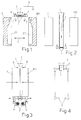
- FIG 1 denotes the discharge mouth of the die which is associated with an extruder and from which the vertical and descending plastic tube 2 - the so-called “parison" - emerges, a section of which tube is cyclically gripped between a mould 3 and a counter-mould 103 which are movable horizontally, as indicated by the arrows 4 and separated from the continuous parison above, with a cutting operation performed by special means (see below) and then, by means of a relative movement of the mould/counter-mould assembly and the die 1, which ensures that the latter is able to function continuously, the said mould/counter-mould assembly is moved away from the die 1 with at least one horizontal displacement component and is transferred into a station where a needle is inserted into one end of the bubble of plastic trapped therein, usually the top end, said needle introducing into the said bubble gas under pressure and causing the bubble to cling to the matching cavities C1, C2 of the mould and the counter-mould, so as to form a pre-chos
- the bottom end of the parison 2 which leaves the die is gripped by any suitable means which, in the case where the parison must remain open at the bottom for ventilation purposes, for example consist of facing noses 5 having their free ends suitably rounded or flattened and which, as shown in the sequence of Figures 5 and 6, are moved together in order to grip the parison in a central zone of limited width, so as to leave the bottom end of the said parison open and free to breathe, for example with a figure-of-eight configuration.
- the noses 5 are made or lined with any material which is non-adhesive with respect to the material which forms the parison 2 so as not to retain parts of this material.
- the noses 5 are mounted on means for moving them towards and away from each other, as indicated schematically by the arrows 6 (see below) and are also associated with raising and lowering means which are denoted schematically by the arrows 7 (see below) and by means of which the said gripping means 5 closed around the bottom end of the parison are made to perform a vertical descending movement which accompanies the said parison 2 in its downward extension.
- the downward travel of the gripping means 5 may occur at the same speed as the natural downward movement of the bottom end of the parison, considering all the components, including the gravitational component, to which the parison is subject during the forming step, or may occur at a speed which is slightly different, i.e. lesser or greater, so as to induce in the parison a compressive or longitudinal stretching action, respectively, which cannot be obtained with the prior art and which could allow an improvement in the characteristic features of the article produced from the parison obtained with this technique.
- the important advantage which arises from this solution consists in the fact that the parison 2 during production is retained both at the top by the die 1 and at the bottom by the dynamic gripping means 5 such that it is prevented from swinging, including when there are substantial air currents produced for example by the movements of the moulds 3, 103 inside the protection cabinet inside which these moulds are usually confined, so as to allow a more rapid execution of said movements, with the advantages resulting therefrom.
- Another advantage which is obtained from the solution described above consists in the fact that, if at least one or both the gripping means 5 are made with materials able to convey the electric charges and if they are connected to earth, as schematically indicated by the connection 8, it is possible to eliminate effectively the electrostatic charges from the parison.
- the arrows 9 denote schematically the cutting means which separate the parison section trapped between mould and counter-mould 3, 103 from the section which continues to be produced by the die 1, so as to allow the latter the necessary operational continuity and allow the transfer of the assembly 3, 103 into the blowing station.
- the gripping means 5 are raised and then lowered at the speed which has been determined for them and in phase synchronism are closed so as to grip the bottom section of the parison which leaves the production die 1, so as to allow the repetition of a new working cycle.
- the return movement of the moulds 3, 103 into the parison gripping station may also occur at a speed higher than that of the prior art, since the parison is already held in opposite zones.
- the supports 10, 10' have mounted on them, rotatable with the middle part, in an arrangement perpendicular to the parisons and parallel with each other, pairs of horizontal screws 15, 15', with oppositely wound threads, with which nut screws 16, 16', for example of the recirculating ball type, co-operate in a precise manner, said nut screws being integral with the end of thin bars 17 which carry the opposite pairs of noses 5 for gripping the bottom end of the parisons 2.
- the pairs of screws 15, 15' are actuated by electric motors 18, 18' with associated encoders 118, 118' which allow management of these same motors with an electric shaft connection, so as to be able to actuate the bars 17 with a precise self-centring movement.
- the said bars or the corresponding nut screws 16, 16' may be designed to co-operate with the associated supports 10, 10' by means of corresponding horizontal guide means similar to the vertical guide means 11, 11'. It is obvious how, from the action of the motors 18, 18', the gripping means 5 obtain the necessary movement towards and away from each other in order to grip and release the parisons, while from operation of the motors 14, 14' the same gripping means 5 obtain the necessary lowering and raising movement, so as to follow the parison during the descending step and return then quickly into the high position for repetition of a new operating cycle.
- the interface 19 managing the motors 14, 14' and 18, 18' with the associated encoders is controlled by an electronic processing unit which is connected to a programming/interrogation unit 21 and which via the connections 122 and 123 is constantly informed by the electronic unit 222 of the speed of rotation of the extruder or extruders 22 for production of the parisons and by the electronic unit 223 of any variation in thickness induced in the said parisons via the special systems 23 for adjusting the axial position of the plugs of the various dies 1.
- the plugs of the various dies are connected by means of respective regulators 24 to a common horizontal beam 25 which, via zones situated symmetrically and at a short distance from its ends, is connected to a pair of linear, vertical, precision actuators 23 which can be managed remotely by means of the electronic control unit 223 and consist, for example, of hydraulic systems or electric motors with electronic speed and phase control, equipped with encoders 323 so that they may be actuated in synchronism, for example using the master and sub-master or slave technique, via the same electronic unit 223 which is intended for programming and control for example via the unit 21.
- the actuators 23 are fixed onto a structure 101 integral with the base of the machine which supports the sets of dies 1. If the actuators 23 consist of electric motors, for example brushless motors, these motors may be designed for synchronous operation with electric shaft connection and may be connected to the beam 25 by means of screw/nut-screw precision systems 26, 26', for example of the recirculating ball type. It is understood that the beam 25 may be connected to the structure 101 situated above and/or to the structure 1 situated below, also by means of vertical precision systems of the guide and slide type.
- Figure 9 illustrates application of the means for dynamic control of the parisons to mould and counter-mould assembles 3, 103 having a small number of forming seats C1, C2 situated alongside each other, for example in a machine comprising two mould/counter-mould assemblies 3-103 and 3'-103', referred to as "twin machine", as described in Italian Patent No. 1,260,295 in the name of the Applicant.
- the support 10 is in this case located on the side of the moulds opposite to that directed towards the blowing station into which the said moulds will be transferred after gripping of the parisons, as indicated by the arrows F, and the said support has, for example, a U shape in plan view, is connected to the fixed support 12 situated below via vertical guide means 11 which are symmetrically arranged and may be raised and lowered with precision by means of the screw and nut-screw system 214 and the electric motor 14 with electronic speed and phase control, as already mentioned with respect to the previous solution according to Figures 7 and 8.
- the two end branches of the support 10 carry the pairs of screws 15, 15' with oppositely wound threads which are actuated by the motors 18, 18' and with which the nut screws 16, 16' integral with the ends of the pairs of parallel and projecting bars 17, 17' co-operate, which bars carry the means 5, 5' for gripping the parisons.
- the bars 17, 17' are prevented from rotating about the pairs of screws 15, 15' and are kept horizontal by cooperation with guide means 27, 27' associated with the ends of the support 10.
Landscapes
- Engineering & Computer Science (AREA)
- Mechanical Engineering (AREA)
- Manufacturing & Machinery (AREA)
- Blow-Moulding Or Thermoforming Of Plastics Or The Like (AREA)
Applications Claiming Priority (2)
| Application Number | Priority Date | Filing Date | Title |
|---|---|---|---|
| ITBO20030743 | 2003-12-11 | ||
| IT000743A ITBO20030743A1 (it) | 2003-12-11 | 2003-12-11 | Procedimento ed apparato per diminuire i tempi di ciclo e per migliorare la qualita'di produzione delle macchine adibite alla estrusione di |
Publications (2)
| Publication Number | Publication Date |
|---|---|
| EP1550545A2 true EP1550545A2 (de) | 2005-07-06 |
| EP1550545A3 EP1550545A3 (de) | 2005-08-31 |
Family
ID=34566891
Family Applications (1)
| Application Number | Title | Priority Date | Filing Date |
|---|---|---|---|
| EP04106071A Withdrawn EP1550545A3 (de) | 2003-12-11 | 2004-11-25 | Verfahren und Vorrichtung zum Extrusionsblasformen von Gegenständen |
Country Status (2)
| Country | Link |
|---|---|
| EP (1) | EP1550545A3 (de) |
| IT (1) | ITBO20030743A1 (de) |
Cited By (2)
| Publication number | Priority date | Publication date | Assignee | Title |
|---|---|---|---|---|
| WO2025098520A1 (zh) * | 2023-11-06 | 2025-05-15 | 山东新华医疗器械股份有限公司 | 一种夹具装置 |
| DE102024115133A1 (de) * | 2024-05-29 | 2025-12-04 | Khs Gmbh | Vorrichtung zum Umformen mindestens eines Vorformlings zu einem Behälter |
Family Cites Families (5)
| Publication number | Priority date | Publication date | Assignee | Title |
|---|---|---|---|---|
| JPH0257317A (ja) * | 1988-08-23 | 1990-02-27 | Mazda Motor Corp | ブロー成形装置 |
| JPH06293059A (ja) * | 1991-04-02 | 1994-10-21 | Ube Ind Ltd | パリソンピンチ方法 |
| JP2748993B2 (ja) * | 1991-05-21 | 1998-05-13 | 宇部興産株式会社 | ブロー成形機 |
| JP2751973B2 (ja) * | 1991-05-24 | 1998-05-18 | 宇部興産株式会社 | ブロー成形におけるパリソンの肉厚制御装置 |
| JP2798160B2 (ja) * | 1991-06-07 | 1998-09-17 | 宇部興産株式会社 | ブロー成形機 |
-
2003
- 2003-12-11 IT IT000743A patent/ITBO20030743A1/it unknown
-
2004
- 2004-11-25 EP EP04106071A patent/EP1550545A3/de not_active Withdrawn
Cited By (2)
| Publication number | Priority date | Publication date | Assignee | Title |
|---|---|---|---|---|
| WO2025098520A1 (zh) * | 2023-11-06 | 2025-05-15 | 山东新华医疗器械股份有限公司 | 一种夹具装置 |
| DE102024115133A1 (de) * | 2024-05-29 | 2025-12-04 | Khs Gmbh | Vorrichtung zum Umformen mindestens eines Vorformlings zu einem Behälter |
Also Published As
| Publication number | Publication date |
|---|---|
| EP1550545A3 (de) | 2005-08-31 |
| ITBO20030743A1 (it) | 2005-06-12 |
Similar Documents
| Publication | Publication Date | Title |
|---|---|---|
| CN107530947B (zh) | 用于由聚合物材料制成的容器的吹塑机 | |
| RU2004120707A (ru) | Устройство и способ компрессионного формования изделий из пластмассы | |
| EP0162458B1 (de) | Einrichtung zur Temperatursteuerung für eine Spritzstreckblasformmaschine | |
| US4468368A (en) | Method for transporting sectional molds | |
| US4552526A (en) | Blow molding machine with mold shuttle structure | |
| EP3173211B1 (de) | Blasformvorrichtung | |
| KR20180002614A (ko) | 2축연신 블로우성형장치 | |
| US20090280206A1 (en) | Machine for blow-moulding containers from extruded parisons | |
| AU597803B2 (en) | Rotary blow molding machine | |
| EP0814948B1 (de) | Verfahren zum herstellen von blasgeformten körpern in verschiedenen grössen und vorrichtung zum ausführen des verfahrens | |
| US6358038B1 (en) | Injection stretch blow molding machine | |
| CA2098843A1 (en) | Linear motor driven label inserter for in-mold labelling | |
| US3640661A (en) | Continuous-parison blow-molding apparatus | |
| EP1550545A2 (de) | Verfahren und Vorrichtung zum Extrusionsblasformen von Gegenständen | |
| US3243847A (en) | Apparatus for blow molding hollow plastic articles | |
| ITMI20131557A1 (it) | Macchina per la realizzazione di contenitori in materiale termoplastico | |
| US5759593A (en) | Apparatus for blow-molding and releasing hollow articles | |
| CN106626329A (zh) | 一种新型的吹瓶机变节距装置 | |
| WO2001023164A9 (en) | Blow molding apparatus | |
| US3700369A (en) | Stripper for blow molding machine | |
| EP2632691B1 (de) | Blasformmaschine zum herstellen von behältern mit niedrigem engergieverbrauch | |
| GB2255929A (en) | Alternately operating blow mould pair | |
| US4560341A (en) | Apparatus for transporting sectional molds | |
| CN112372993B (zh) | 挤出吹塑模开合模装置和挤出吹塑成型机 | |
| GB2205062A (en) | Horixontal axis rotary blow mould transporting apparatus |
Legal Events
| Date | Code | Title | Description |
|---|---|---|---|
| PUAI | Public reference made under article 153(3) epc to a published international application that has entered the european phase |
Free format text: ORIGINAL CODE: 0009012 |
|
| AK | Designated contracting states |
Kind code of ref document: A2 Designated state(s): AT BE BG CH CY CZ DE DK EE ES FI FR GB GR HU IE IS IT LI LU MC NL PL PT RO SE SI SK TR |
|
| AX | Request for extension of the european patent |
Extension state: AL HR LT LV MK YU |
|
| PUAL | Search report despatched |
Free format text: ORIGINAL CODE: 0009013 |
|
| AK | Designated contracting states |
Kind code of ref document: A3 Designated state(s): AT BE BG CH CY CZ DE DK EE ES FI FR GB GR HU IE IS IT LI LU MC NL PL PT RO SE SI SK TR |
|
| AX | Request for extension of the european patent |
Extension state: AL HR LT LV MK YU |
|
| AKX | Designation fees paid | ||
| REG | Reference to a national code |
Ref country code: DE Ref legal event code: 8566 |
|
| STAA | Information on the status of an ep patent application or granted ep patent |
Free format text: STATUS: THE APPLICATION IS DEEMED TO BE WITHDRAWN |
|
| 18D | Application deemed to be withdrawn |
Effective date: 20060301 |