EP1551050B1 - Einpol-sicherungshalterbasis - Google Patents
Einpol-sicherungshalterbasis Download PDFInfo
- Publication number
- EP1551050B1 EP1551050B1 EP02764896A EP02764896A EP1551050B1 EP 1551050 B1 EP1551050 B1 EP 1551050B1 EP 02764896 A EP02764896 A EP 02764896A EP 02764896 A EP02764896 A EP 02764896A EP 1551050 B1 EP1551050 B1 EP 1551050B1
- Authority
- EP
- European Patent Office
- Prior art keywords
- base
- cover
- housing
- covers
- fuse
- Prior art date
- Legal status (The legal status is an assumption and is not a legal conclusion. Google has not performed a legal analysis and makes no representation as to the accuracy of the status listed.)
- Expired - Lifetime
Links
- 239000004020 conductor Substances 0.000 claims description 6
- 210000003739 neck Anatomy 0.000 claims description 4
- 230000009977 dual effect Effects 0.000 claims description 3
- 230000003313 weakening effect Effects 0.000 claims description 2
- 238000009434 installation Methods 0.000 abstract description 2
- 230000000295 complement effect Effects 0.000 abstract 1
- 230000002787 reinforcement Effects 0.000 description 3
- 230000003019 stabilising effect Effects 0.000 description 2
- 231100001261 hazardous Toxicity 0.000 description 1
- 238000003780 insertion Methods 0.000 description 1
- 230000037431 insertion Effects 0.000 description 1
- 238000004519 manufacturing process Methods 0.000 description 1
- 229920000728 polyester Polymers 0.000 description 1
- 230000000717 retained effect Effects 0.000 description 1
- 239000013589 supplement Substances 0.000 description 1
Images



Classifications
-
- H—ELECTRICITY
- H01—ELECTRIC ELEMENTS
- H01H—ELECTRIC SWITCHES; RELAYS; SELECTORS; EMERGENCY PROTECTIVE DEVICES
- H01H31/00—Air-break switches for high tension without arc-extinguishing or arc-preventing means
- H01H31/02—Details
- H01H31/12—Adaptation for built-in fuse
- H01H31/122—Fuses mounted on, or constituting the movable contact parts of, the switch
-
- H—ELECTRICITY
- H01—ELECTRIC ELEMENTS
- H01H—ELECTRIC SWITCHES; RELAYS; SELECTORS; EMERGENCY PROTECTIVE DEVICES
- H01H85/00—Protective devices in which the current flows through a part of fusible material and this current is interrupted by displacement of the fusible material when this current becomes excessive
- H01H85/02—Details
- H01H85/25—Safety arrangements preventing or inhibiting contact with live parts, including operation of isolation on removal of cover
-
- H—ELECTRICITY
- H02—GENERATION; CONVERSION OR DISTRIBUTION OF ELECTRIC POWER
- H02B—BOARDS, SUBSTATIONS OR SWITCHING ARRANGEMENTS FOR THE SUPPLY OR DISTRIBUTION OF ELECTRIC POWER
- H02B1/00—Frameworks, boards, panels, desks, casings; Details of substations or switching arrangements
- H02B1/015—Boards, panels, desks; Parts thereof or accessories therefor
- H02B1/04—Mounting thereon of switches or of other devices in general, the switch or device having, or being without, casing
- H02B1/052—Mounting on rails
- H02B1/0526—Mounting on rails locking or releasing devices actuated from the front face of the apparatus
Definitions
- the present invention refers to a single-pole fuse-holder base, with load disconnection, of the kind using NH type fuses.
- the present invention refers to a single-pole fuse-holder consisting of a body, a housing or base and a cover swivel-mounted on the housing, in which the different accessories will be operated easily and without risk of coming into contact with the conductors or hazardous parts of the base body.
- Fuse-holders are usually made up of a base which is connected to the respective conductor bars, a base or housing and fuse-holders covers which are hinge-mounted on the respective base.
- the covers may occupy an operational or closed position, in which connection is made, or else an out-of-service or open position, which corresponds to the disconnection position of the fuses.
- a blown fuse may be replaced in the open position, and other parts that might be damaged and need replacement can also be removed/refitted in this position.
- Fuse-holder bases of the above-mentioned type are observed, for instance, in Spanish Utility Model n° 1009942 or in international application PCT ES01/00170 , both belonging to the holder.
- the fuse-holder bases described in these patents are made up of a body, a base housing with a slotted configuration, and a hinged cover, which is jointed onto the side walls of the base housing.
- the fuse-holder cover matches up elbow extensions forming pins with their slotted free ends for swivel fitting on respective lugs provided for the purpose on the sides of the housing or base, said cover incorporating means for fastening the fuse in the middle area of its inner face.
- the above-mentioned cover has a special configuration matching up with the slots provided in the elbow pins in order to determine stable open and closed positions, even though the geometry presented by these means that stabilise the limit positions is such that it does not perform the intended function efficiently.
- the terminals that are mounted on the base body are not protected on the inside, with the consequent risks for operators and/or handlers.
- the single-pole fuse-holder base advocated here is designed to overcome the foregoing problems, so that, while being based on the above-described type of fuse holder, it offers a series of special features that give rise to improved optimum operating and safety capabilities in the fuse holder as a whole.
- One of the improvements that is the object of the invention is the single-pole fuse-holder base of claim 1.
- Another feature of the invention refers to the means of jointing between the fuse-holder cover and the housing or base. These means are based on the fact that at the ends of the axial extensions branching out from one of the end parts of the actual cover two large notches, i.e. of considerable depth, are executed, in which are positioned respective lugs provided for the purpose in the sides of the housing or base, with the special feature that, matching up with the inside of those lateral extensions in which the cover notches are made, reinforcements are provided in the form of bosses with a configuration such that, in combination with matching support steps provided on the sides of the housing, they enable the cover to be stabilised and locked transversely, both in the open and in the closed position.
- one of the side steps of the housing presents a lateral protuberance, against which it rests, in order that, in its open position, the cover side extensions are retained against the above-mentioned step and its protuberance, thereby forming a dual stop for the cover, which permits the corresponding handling in its open position with the utmost convenience and safety.
- Another novel feature exhibited by the single-pole base assembly of the invention is the possibility of the base assembly being mounted on DIN rails, for which purpose the rear face of the base has flanges on the outside, which engage with the top of one of the rails, and catches that are disposed under the lower side of the other rail.
- the catches can turn so as to lock against the rail, with the special feature that the catches are operated from inside the housing, at the front end of the base, using a suitable tool for the purpose that acts on a slotted head, which enables the catches to be turned.
- the catches are operated from inside the housing, there is no possibility of coming into contact with live pieces or parts.
- Another novel feature is that access to the wall fastening screws is available without any risk of coming into contact with live parts, as due provision is made, matching up with the position of the fixing screws, that the base body should present cylindrical necks by way of which the respective screwdriver is inserted in a guided and insulated fashion.
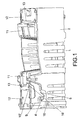
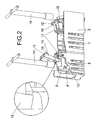
- guards (11) are provided for the respective electrical terminals for the fuses, guards (11) to each of which are jointed, by way of a weakening line (13), covers (12) aligned facing the above-mentioned terminal conductors, with the special feature that said covers are provided with means for stabilising them in the open position to permit easy working on the anchorages by means of the respective tools (14), as well as means for securing the covers (12) in the closed position in order to prevent undue or accidental access to live parts.
- the closed position is obtained by means of little side protuberances (15) which are pressed into the side walls of the housing (2) and act in conjunction with close position limit stops (16), while in open position the stable position of the covers is obtained by means of stops that come into contact with one another and which correspond to references (15') and (16'), said stops being provided on the side edges of the covers (12) and on the corresponding parts of the guards (11), on either side of the folding hinge (13), as may be all observed in figures 1 and 2 .
- the cover (3) presents parallel lateral extensions (6) that are provided with deep notches (7) accommodating lugs or shoulders (4) on the sides of the base or housing (1), so that the cover may be folded by turning it in relation to the aforesaid lugs from a closed position to an open position and vice versa.
- the extensions (6) of the cover (3) have shoulders or reinforcements (8), the outer edge of which (8') engages, when the cover is in the closed position, with matching grooves (5') defined in support steps (5) provided in the sides of the housing (2), while in the maximum opening position the endmost edges (8') are housed in grooves (9') established in support steps (9) in the housing, in order to stabilise and lock the transverse movement of the cover, in both positions.
- the fuse-holder advocated here also has means for stabilising the cover in its open position, on the basis of which the side extensions (6) of the cover (3) are supported on steps (9) in the housing (2) by way of the endmost edge (8'), which is housed in the corresponding groove (9') and locked by contact between the side extensions (8'') and side protuberances (10) from the actual steps (9) which prevent any subsequent turning of the cover, thereby achieving a dual stop that assures a firm and secure position in the opening of the cover (3).
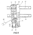
- the single-pole base assembly described can be anchored to a pair of DIN guides (17) (17'), by means of flanges (18) and catches (20) established for the purpose on the outer side (19) of the base (1), the flanges (18) being engaged at the top of the upper guide (17), whilst the catches or latches (20) are anchored at the under side of the lower guide (17').
- the catches (20) can be turned with a tool (24), such as a screwdriver for instance, operating from inside the housing (2) on the front end of the base body (1), thereby preventing access to live parts.
- a tool (24) such as a screwdriver for instance
- the inner end of the aforesaid catches (20) is designed to be duly knurled or configured to receive the action of the tool (24), there also being markings on the bottom of the housing relating to the release or locking positions of said catches (20), as may be observed in figure 7 .
- Figure 9 shows a cross section of the base assembly in which the base body (1) presents holes with necks (21) for the insertion of the assembly wall mounting screws (22) and said necks (21) are designed to permit access to the retaining screws (22) without risk of contact with live parts.
Landscapes
- Fuses (AREA)
- Techniques For Improving Reliability Of Storages (AREA)
- Coupling Device And Connection With Printed Circuit (AREA)
Claims (5)
- Einpol-Sicherungshalterbasis, mit einem Basiskörper (1), einem Gehäuse oder einer Basis (2) und einer schwenkbar mit diesem bzw. dieser verbundenen Abdeckung (3), einschließlich der entsprechenden Anschlüsse und Verankerungen für die Leiter, wobei der Basiskörper (1) Schutzteile (11) aufweist, welche die Sicherungsaufnahmeanschlüsse bedecken,
dadurch gekennzeichnet, dass jedes Schutzteil an einem seiner Endbereiche über Schwenk- und Schwächungslinien (13) an entsprechenden Abdeckungen (12) endet, die mit den Verankerungen der Anschlüsse ausgerichtet sind, wobei jede dieser Abdeckungen (12) mit Schultern (15) und Anschlagteilen (16) versehen ist, welche die Schließposition der Abdeckungen an dem Gehäuse (2) begrenzen und diese gewährleisten, während die Abdeckungen in den Schwenkbereichen (13) Lippen (15') aufweisen, welche an weitere Lippen (16') in dem festen Bereich des Schutzteils (11) angepasst sind und die Abdeckungen (12) in der offenen Position stabilisieren. - Einpol-Sicherungshalterbasis nach Anspruch 1, dadurch gekennzeichnet, dass die Abdeckung (3) an dem Ende, an dem sie mit dem Gehäuse (2) verbunden ist, ein Paar seitlicher Verlängerungen (6) aufweist, die an ihren Enden mit tiefen Ausnehmungen (7) versehen sind, in denen betreffende Ansätze oder Schultern (4) der Seiten des Gehäuses oder der Basis (2) aufgenommen sind, mit dem speziellen Merkmal, dass die Innenflächen dieser an der Abdeckung (3) ausgebildeten seitlichen Verlängerungen (6) mit Innenschultern (8) versehen sind, deren am äußersten Ende gelegener Rand (8') in der Schließposition in Nuten (5') eingreift, welche in an den Seiten des Gehäuses (2) vorgesehenen Haltestufen (5) ausgebildet sind, wobei in der maximalen Öffnungsposition die am äußersten Ende gelegenen Ränder (8') in Nuten (9') aufgenommen sind, die in Haltestufen (9) des Gehäuses (2) ausgebildet sind, um die Abdeckung (3) in Querrichtung zu stabilisieren.
- Einpol-Sicherungshalterbasis nach Anspruch 2, dadurch gekennzeichnet, dass die seitlichen Verlängerungen (6) der Abdeckung in deren Öffnungsposition auf den Haltestufen (9) des Gehäuses (2) ruhen, und zwar mittels des am äußersten Ende gelegenen Rands (8'), der in die entsprechende Nut (9') eingreift und bei Drehung durch Kontakt zwischen dem Rand (8") der seitlichen Verlängerungen (6) und seitlichen Vorsprüngen (10) der eigentlichen Stufen (9) verriegelt wird, wodurch in dieser Position ein zweifacher Anschlag für die Abdeckung (3) gebildet ist.
- Einpol-Sicherungshalterbasis nach Anspruch 1, dadurch gekennzeichnet, dass an dem äußeren Ende (19) der Basis (1) Flansche (18) und Arretierteile (20) ausgebildet sind, um das Befestigen der Basis an DIN-Führungen (17) zu ermöglichen, wobei die Flansche (18) an den oberen Bereich der oberen Führung (17) angekoppelt sind, während die Arretierteile (20) an dem unteren Rand der unteren Führung (17') mittels einer dahingehenden Vorkehrung verriegelt werden können, dass die Arretierteile (20) durch Betätigung eines geeigneten Werkzeugs (24) gedreht werden können, wobei diese Operation vom Inneren des Gehäuses her an dem vorderen Ende der Basis (1) durchgeführt wird, wodurch ein Zugang zu stromführenden Teilen verhindert wird.
- Einpol-Sicherungshalterbasis nach Anspruch 1, dadurch gekennzeichnet, dass der Zugriff auf Wandbefestigungsschrauben (22) ohne Risiko von Kontakt mit stromführenden Teilen möglich ist, wobei dementsprechend vorgesehen ist, dass der Basiskörper (1) entsprechend den Positionen der Befestigungsschrauben (22) mit zylindrischen Hälsen (21) versehen ist, mittels derer der entsprechende Schraubenzieher (24') in geführter und isolierter Weise eingeführt wird.
Applications Claiming Priority (1)
| Application Number | Priority Date | Filing Date | Title |
|---|---|---|---|
| PCT/ES2002/000447 WO2004030007A1 (es) | 2002-09-24 | 2002-09-24 | Base portafusibles unipolar |
Publications (2)
| Publication Number | Publication Date |
|---|---|
| EP1551050A1 EP1551050A1 (de) | 2005-07-06 |
| EP1551050B1 true EP1551050B1 (de) | 2011-03-02 |
Family
ID=32039284
Family Applications (1)
| Application Number | Title | Priority Date | Filing Date |
|---|---|---|---|
| EP02764896A Expired - Lifetime EP1551050B1 (de) | 2002-09-24 | 2002-09-24 | Einpol-sicherungshalterbasis |
Country Status (6)
| Country | Link |
|---|---|
| EP (1) | EP1551050B1 (de) |
| AT (1) | ATE500603T1 (de) |
| AU (1) | AU2002329289A1 (de) |
| DE (1) | DE60239362D1 (de) |
| ES (1) | ES2362352T3 (de) |
| WO (1) | WO2004030007A1 (de) |
Families Citing this family (2)
| Publication number | Priority date | Publication date | Assignee | Title |
|---|---|---|---|---|
| US8419475B2 (en) * | 2011-07-19 | 2013-04-16 | Cooper Technologies Company | Modular open fuseholder with multi-stage positionable cover |
| EP3070730B1 (de) | 2015-03-20 | 2017-11-01 | Pronutec, S.A.U. | Sicherungshalterbasis |
Family Cites Families (6)
| Publication number | Priority date | Publication date | Assignee | Title |
|---|---|---|---|---|
| ES1009942Y (es) * | 1989-04-14 | 1990-04-01 | Pronutec, S.A. | Base unipolar para conexiones electricas desconectable en carga. |
| AT403750B (de) * | 1996-04-12 | 1998-05-25 | Schneider Schaltgeraetebau Und | Lastschaltleiste |
| FR2751465B1 (fr) * | 1996-07-18 | 1998-09-18 | Mecelec Ind | Coupe-circuit electrique muni d'un fusible extractible |
| FR2791818B1 (fr) * | 1999-03-29 | 2001-05-18 | Mecelec Ind | Connecteur de raccordement et ensemble de raccordement electrique entre un jeu de barres et au moins un cable conducteur |
| DE29906759U1 (de) * | 1999-04-16 | 1999-07-08 | Jean Müller GmbH Elektrotechnische Fabrik, 65343 Eltville | Berührschutz für Kontaktelemente eines Sicherungslasttrennschalters |
| FR2811812B1 (fr) * | 2000-07-12 | 2003-06-27 | Mecelec Ind | Connecteur de raccordement et ensemble de raccordement electrique entre un jeu de barres et au moins un cable conducteur |
-
2002
- 2002-09-24 AT AT02764896T patent/ATE500603T1/de not_active IP Right Cessation
- 2002-09-24 ES ES02764896T patent/ES2362352T3/es not_active Expired - Lifetime
- 2002-09-24 WO PCT/ES2002/000447 patent/WO2004030007A1/es not_active Ceased
- 2002-09-24 EP EP02764896A patent/EP1551050B1/de not_active Expired - Lifetime
- 2002-09-24 DE DE60239362T patent/DE60239362D1/de not_active Expired - Lifetime
- 2002-09-24 AU AU2002329289A patent/AU2002329289A1/en not_active Abandoned
Also Published As
| Publication number | Publication date |
|---|---|
| ES2362352T3 (es) | 2011-07-01 |
| DE60239362D1 (de) | 2011-04-14 |
| AU2002329289A1 (en) | 2004-04-19 |
| EP1551050A1 (de) | 2005-07-06 |
| WO2004030007A1 (es) | 2004-04-08 |
| ATE500603T1 (de) | 2011-03-15 |
Similar Documents
| Publication | Publication Date | Title |
|---|---|---|
| US4997386A (en) | Connectors | |
| KR100259893B1 (ko) | 단자모듈및단자미부정렬장치를구비한전기커넥터 | |
| US20020067240A1 (en) | Modular fuseholder | |
| US6794979B2 (en) | Fuse holder assembly | |
| US6759939B2 (en) | Fuse holder assembly | |
| JP4884327B2 (ja) | 開閉器の差込み端子装置 | |
| US11575226B2 (en) | Pass-through plug | |
| FI81461B (fi) | Anordning foer inkoppling av en hjaelpbrytare. | |
| GB2389248A (en) | Fuse | |
| EP1551050A1 (de) | Einpol-sicherungshalterbasis | |
| KR101541196B1 (ko) | 배전반용 부스바 접속장치 | |
| GB2285887A (en) | A locking device for a circuit breaker handle | |
| KR20120001883U (ko) | 회로차단기의 과전류계전기용 정격설정장치 | |
| JP3382115B2 (ja) | 分電盤 | |
| JP2594610Y2 (ja) | 電気接続箱 | |
| US12451300B2 (en) | Disconnect device with interlock mechanism | |
| JP6894669B2 (ja) | ヒューズユニット | |
| JP4506422B2 (ja) | 開閉器の操作ハンドルロック装置 | |
| JP4122979B2 (ja) | スイッチ | |
| EP0940897B1 (de) | Sicherheitsadapter für den Anschluss einer elektrischen Vorrichtung an Sammelschienen | |
| KR200376456Y1 (ko) | 배선용차단기의 보조 커버 | |
| CN118487076A (zh) | 插头和电器设备 | |
| JP2023026790A (ja) | バッテリー端子ユニット | |
| EP1816395B1 (de) | Abgedichteter Steckverbinder zur elektrischen Verbindung mit einer Kontaktschiene | |
| KR200255375Y1 (ko) | 멀티 콘센트 |
Legal Events
| Date | Code | Title | Description |
|---|---|---|---|
| PUAI | Public reference made under article 153(3) epc to a published international application that has entered the european phase |
Free format text: ORIGINAL CODE: 0009012 |
|
| 17P | Request for examination filed |
Effective date: 20050422 |
|
| AK | Designated contracting states |
Kind code of ref document: A1 Designated state(s): AT BE BG CH CY CZ DE DK EE ES FI FR GB GR IE IT LI LU MC NL PT SE SK TR |
|
| AX | Request for extension of the european patent |
Extension state: AL LT LV MK RO SI |
|
| DAX | Request for extension of the european patent (deleted) | ||
| 17Q | First examination report despatched |
Effective date: 20090810 |
|
| GRAP | Despatch of communication of intention to grant a patent |
Free format text: ORIGINAL CODE: EPIDOSNIGR1 |
|
| GRAS | Grant fee paid |
Free format text: ORIGINAL CODE: EPIDOSNIGR3 |
|
| GRAA | (expected) grant |
Free format text: ORIGINAL CODE: 0009210 |
|
| AK | Designated contracting states |
Kind code of ref document: B1 Designated state(s): AT BE BG CH CY CZ DE DK EE ES FI FR GB GR IE IT LI LU MC NL PT SE SK TR |
|
| REG | Reference to a national code |
Ref country code: GB Ref legal event code: FG4D |
|
| REG | Reference to a national code |
Ref country code: CH Ref legal event code: EP |
|
| REG | Reference to a national code |
Ref country code: IE Ref legal event code: FG4D |
|
| REF | Corresponds to: |
Ref document number: 60239362 Country of ref document: DE Date of ref document: 20110414 Kind code of ref document: P |
|
| REG | Reference to a national code |
Ref country code: DE Ref legal event code: R096 Ref document number: 60239362 Country of ref document: DE Effective date: 20110414 |
|
| REG | Reference to a national code |
Ref country code: ES Ref legal event code: FG2A Ref document number: 2362352 Country of ref document: ES Kind code of ref document: T3 Effective date: 20110701 |
|
| REG | Reference to a national code |
Ref country code: NL Ref legal event code: VDEP Effective date: 20110302 |
|
| PG25 | Lapsed in a contracting state [announced via postgrant information from national office to epo] |
Ref country code: GR Free format text: LAPSE BECAUSE OF FAILURE TO SUBMIT A TRANSLATION OF THE DESCRIPTION OR TO PAY THE FEE WITHIN THE PRESCRIBED TIME-LIMIT Effective date: 20110603 Ref country code: SE Free format text: LAPSE BECAUSE OF FAILURE TO SUBMIT A TRANSLATION OF THE DESCRIPTION OR TO PAY THE FEE WITHIN THE PRESCRIBED TIME-LIMIT Effective date: 20110302 |
|
| PG25 | Lapsed in a contracting state [announced via postgrant information from national office to epo] |
Ref country code: NL Free format text: LAPSE BECAUSE OF FAILURE TO SUBMIT A TRANSLATION OF THE DESCRIPTION OR TO PAY THE FEE WITHIN THE PRESCRIBED TIME-LIMIT Effective date: 20110302 Ref country code: CY Free format text: LAPSE BECAUSE OF FAILURE TO SUBMIT A TRANSLATION OF THE DESCRIPTION OR TO PAY THE FEE WITHIN THE PRESCRIBED TIME-LIMIT Effective date: 20110302 Ref country code: FI Free format text: LAPSE BECAUSE OF FAILURE TO SUBMIT A TRANSLATION OF THE DESCRIPTION OR TO PAY THE FEE WITHIN THE PRESCRIBED TIME-LIMIT Effective date: 20110302 Ref country code: AT Free format text: LAPSE BECAUSE OF FAILURE TO SUBMIT A TRANSLATION OF THE DESCRIPTION OR TO PAY THE FEE WITHIN THE PRESCRIBED TIME-LIMIT Effective date: 20110302 Ref country code: BG Free format text: LAPSE BECAUSE OF FAILURE TO SUBMIT A TRANSLATION OF THE DESCRIPTION OR TO PAY THE FEE WITHIN THE PRESCRIBED TIME-LIMIT Effective date: 20110602 |
|
| PG25 | Lapsed in a contracting state [announced via postgrant information from national office to epo] |
Ref country code: BE Free format text: LAPSE BECAUSE OF FAILURE TO SUBMIT A TRANSLATION OF THE DESCRIPTION OR TO PAY THE FEE WITHIN THE PRESCRIBED TIME-LIMIT Effective date: 20110302 |
|
| PG25 | Lapsed in a contracting state [announced via postgrant information from national office to epo] |
Ref country code: EE Free format text: LAPSE BECAUSE OF FAILURE TO SUBMIT A TRANSLATION OF THE DESCRIPTION OR TO PAY THE FEE WITHIN THE PRESCRIBED TIME-LIMIT Effective date: 20110302 Ref country code: PT Free format text: LAPSE BECAUSE OF FAILURE TO SUBMIT A TRANSLATION OF THE DESCRIPTION OR TO PAY THE FEE WITHIN THE PRESCRIBED TIME-LIMIT Effective date: 20110704 |
|
| PG25 | Lapsed in a contracting state [announced via postgrant information from national office to epo] |
Ref country code: SK Free format text: LAPSE BECAUSE OF FAILURE TO SUBMIT A TRANSLATION OF THE DESCRIPTION OR TO PAY THE FEE WITHIN THE PRESCRIBED TIME-LIMIT Effective date: 20110302 Ref country code: CZ Free format text: LAPSE BECAUSE OF FAILURE TO SUBMIT A TRANSLATION OF THE DESCRIPTION OR TO PAY THE FEE WITHIN THE PRESCRIBED TIME-LIMIT Effective date: 20110302 |
|
| PLBE | No opposition filed within time limit |
Free format text: ORIGINAL CODE: 0009261 |
|
| STAA | Information on the status of an ep patent application or granted ep patent |
Free format text: STATUS: NO OPPOSITION FILED WITHIN TIME LIMIT |
|
| 26N | No opposition filed |
Effective date: 20111205 |
|
| PG25 | Lapsed in a contracting state [announced via postgrant information from national office to epo] |
Ref country code: DK Free format text: LAPSE BECAUSE OF FAILURE TO SUBMIT A TRANSLATION OF THE DESCRIPTION OR TO PAY THE FEE WITHIN THE PRESCRIBED TIME-LIMIT Effective date: 20110302 |
|
| REG | Reference to a national code |
Ref country code: DE Ref legal event code: R097 Ref document number: 60239362 Country of ref document: DE Effective date: 20111205 |
|
| PG25 | Lapsed in a contracting state [announced via postgrant information from national office to epo] |
Ref country code: MC Free format text: LAPSE BECAUSE OF NON-PAYMENT OF DUE FEES Effective date: 20110930 |
|
| REG | Reference to a national code |
Ref country code: CH Ref legal event code: PL |
|
| GBPC | Gb: european patent ceased through non-payment of renewal fee |
Effective date: 20110924 |
|
| PG25 | Lapsed in a contracting state [announced via postgrant information from national office to epo] |
Ref country code: IT Free format text: LAPSE BECAUSE OF FAILURE TO SUBMIT A TRANSLATION OF THE DESCRIPTION OR TO PAY THE FEE WITHIN THE PRESCRIBED TIME-LIMIT Effective date: 20110302 |
|
| REG | Reference to a national code |
Ref country code: IE Ref legal event code: MM4A |
|
| REG | Reference to a national code |
Ref country code: FR Ref legal event code: ST Effective date: 20120531 |
|
| PG25 | Lapsed in a contracting state [announced via postgrant information from national office to epo] |
Ref country code: IE Free format text: LAPSE BECAUSE OF NON-PAYMENT OF DUE FEES Effective date: 20110924 Ref country code: CH Free format text: LAPSE BECAUSE OF NON-PAYMENT OF DUE FEES Effective date: 20110930 Ref country code: LI Free format text: LAPSE BECAUSE OF NON-PAYMENT OF DUE FEES Effective date: 20110930 |
|
| PG25 | Lapsed in a contracting state [announced via postgrant information from national office to epo] |
Ref country code: GB Free format text: LAPSE BECAUSE OF NON-PAYMENT OF DUE FEES Effective date: 20110924 Ref country code: FR Free format text: LAPSE BECAUSE OF NON-PAYMENT OF DUE FEES Effective date: 20110930 |
|
| PG25 | Lapsed in a contracting state [announced via postgrant information from national office to epo] |
Ref country code: LU Free format text: LAPSE BECAUSE OF NON-PAYMENT OF DUE FEES Effective date: 20110924 |
|
| PG25 | Lapsed in a contracting state [announced via postgrant information from national office to epo] |
Ref country code: TR Free format text: LAPSE BECAUSE OF FAILURE TO SUBMIT A TRANSLATION OF THE DESCRIPTION OR TO PAY THE FEE WITHIN THE PRESCRIBED TIME-LIMIT Effective date: 20110302 |
|
| PGFP | Annual fee paid to national office [announced via postgrant information from national office to epo] |
Ref country code: DE Payment date: 20190923 Year of fee payment: 18 |
|
| PGFP | Annual fee paid to national office [announced via postgrant information from national office to epo] |
Ref country code: ES Payment date: 20201005 Year of fee payment: 19 |
|
| REG | Reference to a national code |
Ref country code: DE Ref legal event code: R119 Ref document number: 60239362 Country of ref document: DE |
|
| PG25 | Lapsed in a contracting state [announced via postgrant information from national office to epo] |
Ref country code: DE Free format text: LAPSE BECAUSE OF NON-PAYMENT OF DUE FEES Effective date: 20210401 |
|
| REG | Reference to a national code |
Ref country code: ES Ref legal event code: FD2A Effective date: 20221028 |
|
| PG25 | Lapsed in a contracting state [announced via postgrant information from national office to epo] |
Ref country code: ES Free format text: LAPSE BECAUSE OF NON-PAYMENT OF DUE FEES Effective date: 20210925 |