EP1551296B1 - Verfahren, code und system für die untersuchung von gelenkdeformität - Google Patents
Verfahren, code und system für die untersuchung von gelenkdeformität Download PDFInfo
- Publication number
- EP1551296B1 EP1551296B1 EP03765980A EP03765980A EP1551296B1 EP 1551296 B1 EP1551296 B1 EP 1551296B1 EP 03765980 A EP03765980 A EP 03765980A EP 03765980 A EP03765980 A EP 03765980A EP 1551296 B1 EP1551296 B1 EP 1551296B1
- Authority
- EP
- European Patent Office
- Prior art keywords
- joint
- phalange
- contour
- bone
- patient
- Prior art date
- Legal status (The legal status is an assumption and is not a legal conclusion. Google has not performed a legal analysis and makes no representation as to the accuracy of the status listed.)
- Expired - Lifetime
Links
Images


Classifications
-
- A—HUMAN NECESSITIES
- A61—MEDICAL OR VETERINARY SCIENCE; HYGIENE
- A61B—DIAGNOSIS; SURGERY; IDENTIFICATION
- A61B5/00—Measuring for diagnostic purposes; Identification of persons
- A61B5/45—For evaluating or diagnosing the musculoskeletal system or teeth
- A61B5/4528—Joints
-
- A—HUMAN NECESSITIES
- A61—MEDICAL OR VETERINARY SCIENCE; HYGIENE
- A61B—DIAGNOSIS; SURGERY; IDENTIFICATION
- A61B5/00—Measuring for diagnostic purposes; Identification of persons
- A61B5/45—For evaluating or diagnosing the musculoskeletal system or teeth
- A61B5/4504—Bones
- A61B5/4509—Bone density determination
-
- A—HUMAN NECESSITIES
- A61—MEDICAL OR VETERINARY SCIENCE; HYGIENE
- A61B—DIAGNOSIS; SURGERY; IDENTIFICATION
- A61B6/00—Apparatus or devices for radiation diagnosis; Apparatus or devices for radiation diagnosis combined with radiation therapy equipment
- A61B6/50—Apparatus or devices for radiation diagnosis; Apparatus or devices for radiation diagnosis combined with radiation therapy equipment specially adapted for specific body parts; specially adapted for specific clinical applications
- A61B6/505—Apparatus or devices for radiation diagnosis; Apparatus or devices for radiation diagnosis combined with radiation therapy equipment specially adapted for specific body parts; specially adapted for specific clinical applications for diagnosis of bone
-
- G—PHYSICS
- G06—COMPUTING OR CALCULATING; COUNTING
- G06V—IMAGE OR VIDEO RECOGNITION OR UNDERSTANDING
- G06V10/00—Arrangements for image or video recognition or understanding
- G06V10/70—Arrangements for image or video recognition or understanding using pattern recognition or machine learning
- G06V10/74—Image or video pattern matching; Proximity measures in feature spaces
- G06V10/75—Organisation of the matching processes, e.g. simultaneous or sequential comparisons of image or video features; Coarse-fine approaches, e.g. multi-scale approaches; using context analysis; Selection of dictionaries
- G06V10/751—Comparing pixel values or logical combinations thereof, or feature values having positional relevance, e.g. template matching
- G06V10/7515—Shifting the patterns to accommodate for positional errors
-
- G—PHYSICS
- G06—COMPUTING OR CALCULATING; COUNTING
- G06V—IMAGE OR VIDEO RECOGNITION OR UNDERSTANDING
- G06V2201/00—Indexing scheme relating to image or video recognition or understanding
- G06V2201/03—Recognition of patterns in medical or anatomical images
- G06V2201/033—Recognition of patterns in medical or anatomical images of skeletal patterns
Definitions
- the present invention relates to an automated method and system for assaying or monitoring the extent or progression of joint or bone deformity in a joint-degenerative or joint-damaging disease, such as osteoarthritis or deformity joint disease such as rheumatoid arthritis.
- joint-degenerative and joint-damaging diseases such as various forms of arthritis and osteoporosis, that have important health and quality-of-life consequence to patients. Since these diseases tend to be progressive, it is also important to be able to monitor change in joint or bone deformity, for example, in monitoring treatment methods.
- the invention includes, in one aspect, an automated method of assaying or monitoring the extent of joint or bone deformity in a joint-degenerative or joint-damaging disease such as osteoarthritis or osteoporosis, or defromity joint disease such as rheumatoid arthritis, in a subject.
- the method includes first determining from a digitized image of a patient's selected straight bone that terminates at a joint, coordinates of at least one of the right and left bone contours of a selected bone, and determining from the bone contour coordinates above, one or more apices in a region adjacent at least one side of a joint of the selected bone, and, optionally, the coordinates of a minimum width in the middle region of the bone.
- the coordinates so determined are used for selecting a reference bone contour corresponding to one of (i) the contours of confronting joint portions of adjacent straight bones in a normal joint formed by the selected bone; (ii) the contour of a normal joint in a joint region formed by the selected bone; and (iii) the contour from previous x-ray of the subject's bone in the region of the joint.
- a region of the selected bone of the patient is analyzed to assay or monitor the extent of bone deformity in the subject.
- the selected bone may be a finger phalange defining a finger joint, or a toe phalange defining a toe joint.
- An exemplary bone is the middle or proximal phalange of a patient's finger.
- the step of selecting a reference bone contour may include matching contour coordinates for a selected patient phalange with one or more of a plurality of normal-phalange templates from a library of templates.
- the normal-phalange templates in the library may generated, for given patient characteristic(s) related to one or more of gender, age, ethnic group, hand size and body size, as a statistical average of a plurality of normal-phalange templates for the given patient characteristic(s).
- the selecting step may include (i) matching the coordinates of a minimum width in the middle region of the phalange and one or more apices on at least one side of the selected phalange adjacent the joint with corresponding coordinates in a normal-finger template, to identify a normal-finger template that matches the subject phalange, (ii) superimposing the normal-finger template phalange on the image of the patient-finger phalange, and (iii) using the contours of the template finger to identify a scanning box at one of the joints of the selected phalange.
- Selecting step (i) may include using the coordinates of the minimum phalange width to determine a scaling factor for superimposing the template finger of the image of the patient finger. This step may further include matching the determined coordinates of a patient-finger flange with the corresponding coordinates of the phalange from one or more of a set of template phalanges, assessing the difference between the two, and based on this difference, either accepting the template or matching another template from the set.
- Selecting step (iii) may include finding a first line extending through the widest portion of the middle phalange in the region of the MP/PP joint, finding a second line parallel to the first which extends through the widest portion of the adjacent phalange in the region of the same joint, and connecting the two lines with parallel connecting lines to form a rectangular scanning box defined by the widest bone portions.
- the analyzing step may include scanning one of the joints of the selected phalange within the scanning box, in scanning directions substantially parallel to the axis of the finger, to generate contours of the confronting ends of the phalanges in the joint, (ii) generating a profile of the distances between the confronting phalange bone-end contours within the scan box, and (iii) analyzing the profile from (ii) to determine the distance between the confronting ends of the phalanges defining the joint space width and the extent of bone loss at the joint, as an indicator of extent or progression of joint-damaging disease in the subject.
- the analyzing step may further include successively scanning across the joint, in a direction substantially parallel to the finger axis, and the scan line an incremental distance along the width of the scan box, until scans along the entire width of the box have been taken.
- One exemplary phalange is the middle phalange, and the scanning box is placed at the middle phalange/proximal phalange (MP/PP) joint, and scanning step (ii) includes comparing the distances at each point along the scan box in the profile with those representative of a normal-subject MP/PP joint from the same finger as the patient finger.
- MP/PP middle phalange/proximal phalange
- the selecting step may include (i) from the determined coordinates of the contours of the selected phalange, identifying a pair of apices on at least one side of the selected phalange adjacent the joint, and (ii) constructing a straight line between the apices in each pair, where the straight line represents a reference joint contour adjacent the joint region of the selected phalange.
- the analyzing step includes comparing the straight-line contour between a pair of apices with the actual patient contour between the same two points, to determine the extent of concavity of said region with respect to the straight line extending between the two apices.
- the selecting step may include (i) matching the coordinates of a minimum width coordinate in the middle region of the phalange and one or more apices on at least one side of the selected phalange adjacent the joint with corresponding coordinates in a partial or complete normal-finger template, to identify a joint region of a normal-finger phalange template that matches the subject finger joint region, and (ii) superimposing the contour of the template phalange joint region on the image of the patient-finger phalange joint region, where the template contour represents a reference joint contour adjacent the joint region of the selected phalange.
- the analyzing step includes comparing the template line contour in the joint region with the actual patient contour in the same region, to determine the extent to which the actual patient contour deviates from the normal-phalange contour.
- the selecting step may include (i) matching the coordinates of a minimum width coordinate in the middle region of the phalange and one or more apices on at least one side of the selected phalange adjacent the joint with corresponding coordinates in a previous patient x-ray image of the finger phalange, and (ii) superimposing the contour of the previous x-ray image phalange on the image of the patient-finger phalange, where the previous-patient contour represents a reference contour of the selected phalange.
- the analyzing step includes comparing the previous-image contour in the joint region with the actual patient contour in the same region, to determine the extent to which the actual patient contour deviates from the previous-image contour.
- the invention includes machine-readable code that controls the operation of an electronic computer to carry out the above method for assaying or monitoring the extent of joint or bone deformity in a joint-degenerative or joint-damaging disease.
- the system includes an electronic computer, and machine-readable code that controls the operation of the computer to carry out the steps in the above method, where the selecting step in the method includes matching contour coordinates for a selected patient phalange with one or more of a plurality of normal-phalange templates from a library of templates.
- the system also includes a library of normal-phalange templates that is accessible by the code for use in carrying out the selecting step in the method.
- the library forms yet another aspect of the invention.
- the invention includes an automated method for monitoring or assessing the extent of joint or bone deformity in a joint-degenerative or joint-damaging disease, such as arthritis or osteoporosis or deformity joint disease such as rheumatoid arthritis, and a system and machine-readable code for carrying out, or assisting medical personnel in carrying out the method.
- a joint-degenerative or joint-damaging disease such as arthritis or osteoporosis or deformity joint disease such as rheumatoid arthritis
- a system and machine-readable code for carrying out, or assisting medical personnel in carrying out the method.
- the method is based on computer analysis of digitized x-ray images of joints in a patient's long bones, typically one or more flanges or the patient's finger of toe bones, but optionally including other long or elongate bones that terminate in a joint, such as the long bones of the arm or legs.
- long bones typically one or more flanges or the patient's finger of toe bones, but optionally including other long or elongate bones that terminate in a joint, such as the long bones of the arm or legs.
- the method will be described with particular reference to images of a patient's hand, it being understood how the method would be applied to other long bones.
- the x-ray or fluoroscopic image of a patient's hand may be obtained using conventional x-ray methods.
- the x-ray image should include at least one and preferably three fingers on at least one hand of the patient, where the image of each finger includes all of the middle phalange (MP), all of the proximal phalange (PP), and therefore the MP/PP joint, and enough of the metacarpal phalange or bone (MC) to provide an image of the PP/MC joint for that finger.
- a preferred image contains three digits of a hand and a calibration wedge, as illustrated for example in Fig. 1 and detailed with respect to Fig. 3 and in column 6, lines 37-49 of co-owned U.S. Patent No.
- Fig. 1 is an x-ray image 20 of a patient's left hand, showing fingers such as index finger 22, and phalanges, such as the middle phalange (MP) 24, proximal phalange (PP) 26, and the metacarpal bone (MC) 20. Also shown in the figure is a calibration radio-opaque wedge 32.
- the x-ray image is digitized, according to known methods, such as disclosed in the '745 patent, for example, at column 10, lines 21-27, yielding, for example, a 12-bit grey scale image with a resolution of at least 230 dpi.
- a segmentation and processing module (also forming part of the code of the present invention), such as described in the above '745 patent, column 12, line 47 to column 13, line 23, and in related passages describing processing steps 160, 164, 168, 174, 178, and 184) then carries out the following image processing steps:
- the program operates to determine the coordinates of one or more apices, i.e., points of maximum lateral extension or projection, adjacent at least one side of a joint of that phalange, e.g. , at least one side region of the middle phalange MP/PP joint.
- the apices may be local maxima, allowing for more than one apex along each side region of a joint.
- the program also determines the coordinates of the minimum width in the middle region of a selected phalange, e.g. , the MP or PP.
- both apical and minimum width coordinates are typically used in selecting reference contours, although in one embodiment (Embodiment 2), minimum-width coordinates may not be required.
- the reference contours are the contours of confronting portions of adjacent phalanges in a normal-finger joint.
- the reference contours selected are the contours of a normal-finger joint in a region adjacent at least one side of a joint of the selected phalange.
- the "normal-finger" contour may be represented either by a straight line between a pair of apical joints adjacent the joint region (Embodiment 2), or a contour from a normal-bone template in that joint region (Embodiment 3).
- the reference contour is derived from an earlier patient x-ray image of the same bone region.
- a region of the selected joint of the patient is then scanned to assay or monitor the extent of joint or bone degeneration in the subject.
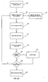
- Figs. 2A and 2B show a flow diagram of steps performed by the code of the invention, in carrying out the method of Embodiment 1.
- the coordinates that are determined from the x-ray images are the coordinates at the left and right edges of the bone at its narrowest width (Min), and the apical coordinates corresponding to coordinates at the ends of a line through the widest portion of the phalange (Max) adjacent one or both joints of that phalange, for example, the greatest widths at the top and bottom joint regions of the middle flange.
- the coordinates are determined by using the left and right bone edge contours to find the minimum bone width of the middle phalange. Starting from the first coordinate of the left bone edge contour, the program finds the corresponding coordinate that has the same Y coordinate from the right bone edge contour. The width at this Y coordinate will be the difference between the two X coordinates. After creating the width profile, the middle phalange minimum width coordinates and the coordinates at the widest points of both top and bottom joint regions are determined. Embodiment 3 below details the algorithm for finding minimum width coordinates. The same approach is used for finding coordinates at a maximum width in the joint regions of the selected phalange.
- the program operates at 36 to find a normal-bone template that closely matches the selected patient phalange, e.g. , the MP, in size and shape.
- the templates are selected from a library 38 of normal-bone phalanges.
- the template may be generated statistically or arbitrarily.
- a statistical template can be made after sampling a large number of normal phalange data and "averaging" them. This requires a large set of "good representative" data.
- An arbitrary template is created using a selected phalange contour. This is possible when the shape of an object of interest is uniform and regular.
- the statistical template will preferably be specific for gender, height and/or hand size. In order to cover minor variations in shape of phalanges depending on gender and age group, there is a preferable set of templates for each finger's every phalange. In an exemplary method, and based on the matching time and the shape variances, five to six templates for each set are chosen.
- a selected template from the set is then overlaid on a real bone image.
- the minimum width of the middle phalange found from above is used as an anchor point to overlay the template.
- the anchor point as well as the scale factor, the template is shrunk or expanded to fit the real phalange.
- the scaled template is superimposed on the patient phalange for template matching, as at 41.
- a minimum error function r for all templates tested is stored. This lowest error function is compared with the error function of the latest template match at 44. If the latest template match is lower than the stored error function, the new match is saved to file 46, along with its error function. If the latest template error function is higher than the existing function, the program proceeds to test the next template, through the logic of 48, 49, until all of the library templates have been tested against the selected patient phalange. When this process is completed, the template having the lowest error function is identified as the best match template, at 50.
- the template is retained; otherwise, a new template is evaluated, and the process repeated until an appropriate template is found, either as a good-match or as the best-match, i.e., the one with the minimum error.
- the template that generates the minimum error parameter is selected for the next stage operations, which are given in flow diagram form in Fig. 2B.
- a MP template is found, it is superimposed on the patient template, at 52, and using the outlines of the template, the program constructs a rectangular scan box 53 (Box 1, the upper box in Fig. 3) for the MP/Proximal phalange (PP) joint is defined by
- the construction of the scanning box is indicated at 64 in Fig. 2B.
- a scanning and profile analysis algorithm given in Fig. 2B is now employed to scan the patient MP and PP bone-end contours, by scanning in a direction parallel to the bone axis, across the entire length of Box 1.
- Inside the scan box is a small sub-image as shown in Fig. 4 including joints between either MP and PP or joints between PP and MCP.
- a series of mathematical image processes including Unsharp Mask, Local Equalization and Median Filter are then be applied to the sub-image for the purpose of enhancing image quality by reducing both the high and low frequency noise.
- the start point will be the center point of the scan box, indicated by scan line 62.
- the program scans line-by-line parallel to the bone axis (vertical in Fig.3) toward each side of the box until reaches the two ends. This operation is indicated at 66 in Fig. 2B. A gray level profile is then created for each scanned line.
- a similar approach is used to determine the joint space narrowing at the PP/MCP bone joints. Based on the top portion of the PP contour from the operation above, the MP width and height, the program calculates a scale factor for the PP. With this scale factor, a PP template (preferably taken from the same template set for the MP) is overlaid. The match process is similar to that described above for the MP. This approach assumes that the axis of the finger is a straight line. If this is not the case, the PP template has to be rotated with respect to the MP until the two template phalanges are aligned with the patient phalanges.
- This score provides another indicator of the extent or progression of joint loss in the patient hand.
- Embodiment 2 described in this section and Embodiment 3 described in the next sections are designed to assess the extent of bone loss in the joint region of a selected bone, e.g. , phalange, using normal-bone contours to as reference contours.
- the patient's own earlier x-ray images may be used as the reference contours, for assessing the change in bone erosion over time. This approach is detailed below as Embodiment 4.
- Embodiment 2 utilizes a method of determining convex - concave property of the top portion of the lateral bone contours.
- Fig. 6 shows the concave property of a PP phalange 74 having a contour 76 shown in black trace.
- AP anterior-posterior
- the normal shape of the top portion of the bones of interest exhibits an outward convex. If erosion has taken place, it is possible to detect various concave shapes in those areas. Using two points and a straight line that connects them, it is possible to determine how concave the contour is in the area and thus the existence of erosion.
- contour 76 of the phalange has two distinctive apices (maxima), point P and point Q.
- Apical point P, indicated at 78, is found by the algorithm below, corresponding to box 80 in Fig. 5, which is a flow diagram of the steps in the method.
- the second point, Q, shown at 82 in Fig. 6, is determined by the same method as described above but by scanning the contour in a bottom-up direction. These steps are generally represented by box 84 in Fig. 5.
- Q x i ⁇ y i ⁇ B i .
- xj ⁇ X j+1 and (x j+1 ,y j+1 ) ⁇ B L and yi # y j , and q ⁇ j ⁇ m, m and q are defined the same as above.
- a straight line 83 between the points as indicated by box 86 in Fig. 5.
- This line represents a "normal" bone contour in this region (As indicated above, a normal bone may be slightly convex in this region).
- the points making up the patient bone contour segment between points P and Q can then be compared to the number of pixels making up the strait line connecting points P and Q (red trace in Fig.4), to analyze the deviation between the straight line and the patient contour between the same two points.
- One measure of this deviation is the number of pixels contained in the each contour between points P and Q, the straight line contour represented the smallest pixel number between the two points, and the number of pixels in the patient contour being related to the extent of concavity in the contour.
- This operation is indicated at 88 in Fig. 5.
- the comparison of pixel numbers in the two contours can be expressed with criteria for a certainty or confidence factor (CF), as at 90 in Fig. 5.
- CF certainty or confidence factor
- the system by default determines that the erosion exists if the CF exceeds a certain threshold, e.g. , 60°/a, which can be determined by matching the automated algorithm to expert's assessment.
- the method in this embodiment uses a portion of MP or PP templates to predict or estimate a normal contour (without erosion). Then, the current contour can be compared against the estimated contour to determine the existence and severity of the erosion.
- the algorithm defines two landmark points (described below in detailed steps) and applies a matching algorithm only on the contour points between them.
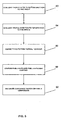
- the algorithm is shown in flow diagram in Fig. 7.
- the program finds the coordinates for an apical point P, as carried out in Embodiment 2, and the coordinates for the minimum width of the phalange (points N), as discussed below. These points are shown at P and N for a patient middle phalange 108 in Fig. 8A, and at P t and N t , for a normal-bone template 110 in Figs. 8B.
- N ( x n , y n ) ⁇ B r , where B c is the current phalange contour ( x a , y n ) ⁇ B c , ( x b , y n ) ⁇ B r , min (
- the program examines, for each y coordinate along the length of the bone, a coordinate for which the absolute value of x a -x b on opposite sides of the bone that has a minimum value.
- the pair of x,y coordinates so identified are designated N.
- a similar algorithm finds the y coordinates adjacent at least bone end for which the absolute value X a -X b is a maximum, and designates the corresponding x,y values as points P.
- These algorithms are also applied in Embodiments 1 and 4 for finding minimum-width coordinates and maximum-width apical coordinates.
- a template is selected at 94 from a library of templates 96, constructed as described with respect to Embodiment 1.
- the program first calculates at 98 a scaling factor SF coordinates N, N t , P, and P t determined for the patient and template contours as above.
- the scaling factor is calculated as the as the ratio of distances between P and N vs P t and N t .
- the program calculates a rotation matrix for orienting the template and patient contours in the same plane, as indicated by box 100 in Fig. 7. This is done, as illustrated in Figs. 9A and 9B, by forming lines P-N and N-N in the patient contour and corresponding lines P t -N t and N t -N t in the template contour.
- the rotation matrix is then determined by calculating the rotation angle, ⁇ , as the angle between the line connecting P and N, and P t and N t , respectively. That is ⁇ is the difference between the angle N-N-P in the patient contour and N t -N t -P t in the template contour.
- Figs. 10A and 10B show the superimposition of the template contour on the patient contour before and after application of the rotation matrix.
- the program now determines, at 102, a translation vector T for transforming each point between P t and P t of the template contour into the corresponding contour region between P and P in the patient contour.
- Fig. 11 shows the superposition of a template contour on a patient contour employing the matrix. As seen, the matrix has the effect of superimposing the template points N t and P t on the corresponding patient contour point N and P, respectively, for templates that have a good fit with the patient contour.
- the extent of erosion of the patient bone is analyzed, as at 106, by comparing the template line contour in the joint region with the actual patient contour in the same region, to determine the extent to which the actual patient contour deviates from the normal-phalange contour.
- the program analyzes the differences in contours between N and P on the left side of the bone, P and P across the top of the bone, and P and on the right side of the bone.
- the algorithm scans in the y direction, recording for each y coordinate, the difference between the patient and contour x coordinate positions. Across the top of the bone, the scan is in the x direction, the difference value is for the contour y coordinates.
- an erosion value is determined, e.g ., the average value of "negative" contour differences, that is, contour differences in which the template value is greater than the patient contour value.
- the above method may be employed with either partial or total template.
- This method employs basically the same technique as described below for Embodiment 4, except that due to shape and size variances between the template and the real phalange contour, a number of small non-matched regions might exist.
- the subsequent necessary step is to analyze each of those regions and determine if it is generated by the minor variances or actual erosion.
- the criteria used is based on a shape analysis algorithm: long and thin regions are most likely generated by the minor variances, while jogged areas are erosions.
- a patient has the bone contour obtained and stored in the previous visit or analysis, it is possible to accurately monitor the progression of erosion by using it as a template.
- the contour of the previous analysis is retrieved from the database and used as a shape template by overlaying it on the current contour, as shown at 112 in Fig. 13.
- the black contour represents the result of the current analysis, and the yellow one obtained in the previous analysis, respectively.
- the orange area indicates increased erosion development whereas the green area on the right shows improvement in erosion.
- Fig. 12 The operation of the algorithm in this method is shown in Fig. 12. Initially, the program constructs the current patient contour (box 114), according to previously discussed methods. This contour is then matched at 116 with one or more earlier patient-phalange contours stored at 118. The operation of the algorithm for matching the current (B c ) and previous (B p ) bone contours, and for assessing the differences between the two are as follows:
- the scaling factor indicates how much the template should be expanded or shrunk. This is simply calculated by comparing lengths of bones in the two contours. Since these two contours are from the same patient, they are expected to yield a value close to 1.
- SF max y ⁇ B c - min y ⁇ B c max y ⁇ B p - min y ⁇ B p
- the anchoring points determine whether a translation and/or rotation are needed. They are used to align the shape template with the current contour. In this case, axes of each contour are aligned to achieve the overlay.
- x ⁇ ⁇ y ⁇ SF * x - ⁇ x , y - ⁇ y
- ⁇ x x c - x p , x p , ⁇ y ⁇ B p
- x c ⁇ y ⁇ B c ⁇ y min y ⁇ B c - min y ⁇ B p
- the program determines an overlay function which is used in assessing the differences in the areas of the two contours (box 120 in Fig. 12).
- the analysis may initial require a correction to place the bones, e.g. , phalanges forming the joint being analyzed along the same long axis.
- the correction method described below is based on the observation that an axis of a finger is composed of a straight line axis of a distal phalange, that of a middle phalange and that of a proximal phalange. Therefore, even if the overall axis of a finger may be severely curved, its axis can be obtained by composing each of the three straight line axes for the three bones inside a finger.
- Each step can be elaborated as follows. First, obtain a contour of a finger, and obtain an approximate straight line axis of a finger using any conventional method, as indicated in Fig. 14A, which shows a severely curved finger 122, a straight-line axis 124 determined from the distal and middle phalanges, and the outer contour of the finger at 126.
- One algorithm calculates a central axis of the finger based on the center of gravity of the finger as determined from the outer contour. The entire finger is then rotated to an upright position along this axis, as indicated in Fig. 14A, that is, the center axis is oriented to a vertical line.
- the program scans the finger along the length of the axis (the y axis) to determine a midpoint along each scan line (x-axis direction). These steps are illustrated in Fig. 14B, which shows midpoints 130, 134 for scan lines 128, 132, respectively.
- the program now connects the first and last midpoints, to give line 131.
- the program now calculates the distance between line 131 and each midpoint.
- the point on the scan line having the maximum distance from line 131 is determined, referred to herein as P 1 , and is identified at 144 in Fig. 14C.
- point P 1 is close to the MP/PP joint in this figure.
- the program constructs a line 136 from the highest midpoint to point P 1 , and a second line 142 from point P 1 to the lowest scan line midpoint.
- Each finger phalange is now rotated, as shown in Fig. 14E, to bring the line segment assigned to it into line with center axis 124.
- the program then operates to connect the three rotated phalanges from top to bottom to obtain artificially composed straight finger contour. This "straightened" contour is then is for further analysis in the method above.
- the invention thus includes a method for orienting a severely curved finger into a straightened condition, for purposes of establishing a more normal orientation of the finger preliminary to the method steps above, where the bone contour is matched with template of previous-patient contours.
- the method includes constructing horizontal scan lines along the length of the finger, and determining midpoints of these scan lines. These midpoints are then used find points of maximum deviation of a line connecting the end midpoints with the midpoints themselves, as a basis for dividing the connecting line into two lines intersecting at this point of maximum deviation. Once the one or more points of maximum deviation are found, the separate portions of the finger may be rotated to bring each connecting line into conformity with a common vertical axis.
- BMD adjacent to the joint space is calculated pixel-by-pixel ( U.S. patent No. 6,246,745 ).
- This BMD is a local bone loss value that is different from the comprehensive phalange BMD reported from the patent 745. It only evaluates the BMD adjacent to the joint area so that it will reflect the progression of the joint degeneration more precisely.
- this local BMD can be further separated to trabecular(axial) and cortical (peripheral) BMD, while the combined cortical thickness near the joint is considered as a better indicator for early RA disease.
- Threshold algorithm A local histogram profile is created for the region inside the scan box shown in Fig. 4. A cortical threshold is defined and a binary image will be created based on this threshold. A bug-following algorithm from pending patent No. 09/430054 is then used to extract the cortical area.
- Region growing algorithm This algorithm starts with a set of cortical seed points that selected immediately from the phalange confront ends to grow regions by appending to each seed point those neighboring pixels that have similar gray levels.
- An overall radiological score for monitoring the progression of the bone deformity disease will be reported after an X-ray radiograph is analyzed using the above method.
- the score will include the information of JSW, bone erosion and periarticular BMD status.
- the method allows for accurate quantitative determination and monitoring of both joint deformity and bone erosion, using only standard patient x-ray images for analysis.
- the method as embodied in the code and system of the invention, is carried out in a nearly fully automated manner, allowing rapid and relatively assessment of joint and bone degeneration.
Landscapes
- Health & Medical Sciences (AREA)
- Life Sciences & Earth Sciences (AREA)
- Engineering & Computer Science (AREA)
- Medical Informatics (AREA)
- General Health & Medical Sciences (AREA)
- Physics & Mathematics (AREA)
- Veterinary Medicine (AREA)
- Molecular Biology (AREA)
- Public Health (AREA)
- Animal Behavior & Ethology (AREA)
- Surgery (AREA)
- Heart & Thoracic Surgery (AREA)
- Biomedical Technology (AREA)
- Pathology (AREA)
- Dentistry (AREA)
- Oral & Maxillofacial Surgery (AREA)
- Orthopedic Medicine & Surgery (AREA)
- Biophysics (AREA)
- Theoretical Computer Science (AREA)
- Rheumatology (AREA)
- Computer Vision & Pattern Recognition (AREA)
- High Energy & Nuclear Physics (AREA)
- Optics & Photonics (AREA)
- Evolutionary Computation (AREA)
- General Physics & Mathematics (AREA)
- Software Systems (AREA)
- Databases & Information Systems (AREA)
- Multimedia (AREA)
- Artificial Intelligence (AREA)
- Nuclear Medicine, Radiotherapy & Molecular Imaging (AREA)
- Computing Systems (AREA)
- Radiology & Medical Imaging (AREA)
- Apparatus For Radiation Diagnosis (AREA)
- Image Analysis (AREA)
- Image Processing (AREA)
- Measurement Of The Respiration, Hearing Ability, Form, And Blood Characteristics Of Living Organisms (AREA)
- Investigating Or Analysing Biological Materials (AREA)
- Plural Heterocyclic Compounds (AREA)
- Television Systems (AREA)
Claims (27)
- Automatisches Verfahren zum Überprüfen oder Überwachen des Ausmaßes einer Gelenk- oder Knochendeformität bei einer Gelenkdegeneration- oder Gelenkbeschädigungskrankheit einer Person,
umfassend die Schritte(a) Bestimmen der Koordinaten von mindestens einer rechten und linken Knochenkontur eines ausgewählten Knochens von einem digitalisierten Röntgenbild eines ausgewählten, an einem Gelenk endenden Knochen eines Patienten,(b) Bestimmen der Koordinaten von einer oder mehreren Spitzen in einem mindestens an einer Seite des durch den ausgewählten Knochen gebildeten Gelenks benachbarten Bereich oder und wahlweise der Koordinaten einer minimalen Breite in dem mittleren Bereich des Knochens aus den in Schritt (a) bestimmten Koordinaten der Knochenkontur,(c) Verwenden der in Schritt (b) bestimmten Koordinaten zur Auswahl einer Bezugsgelenkkontur entsprechend (i) einer der Konturen gegenüberliegender Gelenkabschnitte benachbarter gerader Knochen in einem durch den ausgewählten Knochen gebildeten normalen Gelenk; (ii) der Kontur eines normalen Gelenks in einem durch den ausgewählten Knochen gebildeten Gelenkbereich; und (iii) der Kontur in dem Bereich des Gelenks von einem vorherigen Röntgenbild des Knochens der Person und(d) geführt durch die in Schritt (c) ausgewählte Bezugsgelenkkontur, Analysieren eines Bereichs des ausgewählten Gelenks des Patienten zum Überprüfen oder Überwachen des Ausmaßes der Knochen- oder Gelenkdeformität bei der Person. - Verfahren nach Anspruch 1, wobei der ausgewählte Knochen ein in einem Fingergelenk endendes Fingerglied oder ein in einem Zehengelenk endendes Zehenglied darstellt.
- Verfahren nach Anspruch 2, wobei Schritt (c) den Abgleich der in Schritt (b) bestimmten Konturkoordinaten für ein ausgewähltes Patientenglied mit einem oder mehreren Normal-Glied-Vorlagen aus einer Gliedvorlagenbibliothek umfasst.
- Verfahren nach Anspruch 3, wobei jede Normal-Glied-Vorlage in einer Bibliothek für ein gegebenes Patientenmerkmal(e), das eines oder mehrere von Geschlecht, Alter, ethnischer Gruppe, Handgröße, Körpergröße betrifft, als ein statischer Mittelwert einer Mehrzahl von Normal-Glied-Vorlagen für das gegebene Patientenmerkmal(e) erzeugt wurde.
- Verfahren nach Anspruch 2, wobei der ausgewählte Knochen das mittlere oder proximale Glied eines Fingers eines Patienten darstellt.
- Verfahren nach Anspruch 5 zur Verwendung bei der Überprüfung oder Überwachung einer Gelenkraumbreite bei einem Patientengelenk, wobei
Schritt (c) (ci) den Abgleich der Koordinaten einer minimalen Breite in dem mittleren Bereich des Gelenks und einer oder mehrerer Spitzen auf mindestens einer Seite des ausgewählten Gelenks benachbart zu dem Gelenk mit entsprechenden Koordinaten in einer Normal-Finger-Vorlage, zum Identifizieren einer Normal-Finger-Vorlage, die dem menschlichen Glied entspricht, (cii) übereinander Anordnen der normalen Fingergliedvorlage mit dem Bild des Patientenfingergliedes, und (ciii) Verwenden der Konturen des Vorlagefingers zum Kennzeichnen eines Abtastkastens an einem der Gelenke des ausgewählten Gliedes umfasst, und
Schritt (d) (di) das Abtasten eines der Gelenke des ausgewählten Gliedes innerhalb des Abtastkastens in im Wesentlichen parallel zur Achse des Fingers verlaufenden Abtastrichtungen, um Konturen der gegenüberliegenden Enden der Glieder in dem Gelenk zu erzeugen, (dii) das Erzeugen von Profilen der Abstände zwischen den gegenüberliegenden Gliedknochenendkonturen in dem Abtastkasten und (diii) das Analysieren der Profile von (dii) zur Bestimmung des Ausmaßes des Knochenschwundes an dem Gelenk als eine Anzeige des Ausmaßes oder des Fortschritts der Gelenkbeschädigungskrankheit bei der Person, umfasst. - Verfahren nach Anspruch 6, wobei das ausgewählte Glied das mittlere Glied darstellt, und der Abtastkasten an dem Gelenk des mittleren Gliedes/proximalen Gliedes (MP/PP) angeordnet ist.
- Verfahren nach Anspruch 7, wobei Schritt (ci) die Verwendung der Koordinaten der minimalen mittleren Gliedbreite zur Bestimmung eines Normierungsfaktors zum übereinander Anordnen des Vorlagefingers mit dem Bild des Patientenfingers umfasst.
- Verfahren nach Anspruch 7, wobei der Schritt (ci) weiter den Abgleich der bestimmten Koordinaten des mittleren Gliedes des Patientenfingers mit den entsprechenden Koordinaten des mittleren Gliedes von jedem Vorlagefinger eines Satzes, das Werten der Differenz zwischen den beiden und, basierend auf dieser Differenz, entweder die Annahme der Vorlage oder das Abgleichen einer weiteren Vorlage aus dem Satz umfasst.
- Verfahren nach Anspruch 7, wobei Schritt (ciii) das Auffinden einer sich durch den breitesten Abschnitt des mittleren Gliedes in dem Bereich des MP/PP-Gelenkes erstreckenden ersten Linie, das Auffinden einer zweiten zur ersten parallelen Linie, die sich durch den breitesten Abschnitt des benachbarten Gliedes in dem Bereich desselben Gelenkes erstreckt, und das Verbinden der zwei Linien mit parallelen Verbindungslinien zur Ausbildung eines mittels der breitesten Knochenabschnitte gebildeten rechtwinkligen Abtastkastens.
- Verfahren nach Anspruch 5, wobei Schritt (d) das aufeinanderfolgende Abtasten über das Gelenk in einer im Wesentlichen zur Fingerachse parallelen Richtung und der Abtastlinie in einem inkrementellen Abstand längs der Breite des Abtastkastens, bis das Abtasten längs der gesamten Breite des Kastens durchgeführt wurde, umfasst.
- Verfahren nach Anspruch 11, wobei das ausgewählte Glied das mittlere Glied darstellt und der Abtastkasten an dem Gelenk des mittleren Gliedes/proxiamalen Gliedes (MP/PP) angeordnet ist, und Schritt (dii) den Vergleich der Abstände an jedem Punkt längs des Abtastkastens in dem Profil mit jenen, die einem normalen menschlichen MP/PP-Gelenk von dem gleichen Finger wie dem Patientenfinger entsprechen, umfasst.
- Verfahren nach Anspruch 5 zur Verwendung bei der Überprüfung oder Überwachung des Knochenschwundes eines Patientengelenks, wobei
Schritt (c) (ci) die Kennzeichnung eines Paares von Spitzen an mindestens einer Seite des benachbart zu dem Gelenk ausgewählten Gliedes von den bestimmten Koordinaten der Konturen des ausgewählten Gliedes, und (cii) den Aufbau einer geraden Linie zwischen jeder der Spitzen in jedem Paar umfasst, wobei die gerade Linie eine Bezugsgelenkkontur benachbart zu dem Gelenkbereich des ausgewählten Gliedes darstellt, und Schritt (d) den Vergleich der geraden Linienkontur zwischen einem Paar Spitzen mit der tatsächlichen Patientenkontur zwischen den gleichen zwei Punkten umfasst, um das Ausmaß der Konkavität des Bereichs in bezug auf die sich zwischen den zwei Spitzen erstreckenden geraden Linie zu bestimmen. - Verfahren nach Anspruch 13, wobei das ausgewählte Glied das proximale Glied und das Gelenk das MP/PP-Gelenk darstellt.
- Verfahren nach Anspruch 5 zur Verwendung bei der Überprüfung oder Überwachung des Knochenschwundes bei einem Patientengelenk, wobei
Schritt (c) (ci) das Abgleichen der Koordinaten von einer minimalen Breitenkoordinate in dem mittleren Bereich des Gliedes und einer oder mehreren Spitzen an mindestens einer Seite des ausgewählten Gliedes benachbart zu dem Gelenk mit entsprechenden Koordinaten in einer teilweise oder vollständigen Normal-Finger-Vorlage zur Kennzeichnung eines Gelenkbereichs einer Vorlage eines Gliedes eines normalen Fingers, der dem Gelenkbereich des menschlichen Fingers entspricht, und (cii) übereinander Anordnen der Kontur des Gelenkbereichs des Vorlagegliedes mit dem Bild des Gelenkbereichs des Patientenfingergliedes, wobei die Vorlagekontur eine Bezugsgelenkkontur benachbart zu dem Gelenkbereich des ausgewählten Gliedes darstellt, umfasst, und
Schritt (d) den Vergleich der Linienkontur der Vorlage in dem Gelenkbereich mit der tatsächlichen Patientenkontur in dem gleichen Bereich umfasst, um das Ausmaß zu bestimmen, bis zu dem die tatsächliche Patientenkontur von der Kontur des normalen Gliedes abweicht. - Verfahren nach Anspruch 15, wobei das ausgewählte Glied das proximale Glied und das Gelenk das MP/PP-Gelenk darstellt.
- Verfahren nach Anspruch 5 zur Verwendung bei der Überprüfung oder Überwachung des Knochenschwundes bei einem Patientengelenk, wobei
Schritt (c) (ci) das Abgleichen der Koordinaten von einer minimalen Breitenkoordinate in den mittleren Bereich des Gliedes und einer oder mehrerer Spitzen an mindestens einer Seite des ausgewählten Gliedes benachbart zu dem Gelenk mit den entsprechenden Koordinaten in einem vorherigen Röntgenbild des Fingergliedes und (cii) das übereinander Anordnen der Kontur des Gelenkbereichs des Gliedes des vorherigen Röntgenbildes mit dem Gelenkbereich des Gliedes des Patientenfingers, wobei die vorherige Patientenkontur eine zum Gelenkbereich des ausgewählten Gliedes benachbarte Bezugsgelenkkontur darstellt, umfasst, und Schritt (d) das Vergleichen der vorherigen Bildkontur in dem Gelenkbereich mit der tatsächlichen Patientenkontur in dem gleichen Bereich umfasst, um das Ausmaß zu bestimmen, bis zu dem die tatsächliche Patientenkontur von der vorherigen Bildkontur abweicht. - Verfahren nach Anspruch 17, wobei das ausgewählte Glied das proximale Glied und das Gelenk das MP/PP-Gelenk darstellt.
- Maschinen lesbarer Code zur Steuerung des Betriebs eines elektronischen Rechners zur Durchführung eines Verfahrens zur Überprüfung oder Überwachung des Ausmaßes einer Gelenk- oder Knochendeformität bei einer degenerativen Gelenk- oder Gelenkschädigungskrankheit bei einer Person, umfassend die Schritte(a) Bestimmen der Koordinaten von mindestens einer der rechten und linken Knochenkonturen eines ausgewählten Knochens von einem digitalisierten Röntgenbild eines ausgewählten geraden Knochens eines Patienten, der in einem Gelenk endet,(b) Bestimmen der Koordinaten von einer oder mehreren Spitzen in einem mindestens an einer Seite des durch den ausgewählten Knochen gebildeten Gelenks benachbarten Bereich und wahlweise der Koordinaten einer minimalen Breite in dem mittleren Bereich des Knochens von den in Schritt (a) bestimmten Knochenkoordinaten,(c) Verwenden der in Schritt (b) bestimmten Koordinaten zur Auswahl einer Bezugsgelenkkontur entsprechend einer (i) der Konturen der gegenüberliegenden Gelenkbereiche benachbarter gerader Knochen in einem durch den ausgewählten Knochen gebildeten normalen Gelenk, (ii) der Kontur eines normalen Gelenks in einem zumindest einer Seite des durch den ausgewählten Knochen gebildeten Gelenks benachbarten Bereich, und (iii) der Kontur des Gelenks der Person in einem zumindest einer Seite des durch den ausgewählten Knochen gebildeten Gelenks benachbarten Bereich, und(d) geführt durch die in Schritt (c) ausgewählte Bezugsgelenkkontur, Analysieren eines Bereichs des ausgewählten Gelenks des Patienten zur Überprüfung oder Überwachung des Ausmaßes der Gelenk- oder Knochendeformität bei der Person.
- Code nach Anspruch 19, wobei der ausgewählte Knochen ein ein Fingergelenk bildendes Fingerglied oder ein ein Zehengelenk bildendes Zehenglied darstellt.
- Code nach Anspruch 20, wobei der ausgewählte Knochen ein mittleres oder ein proximales Glied eines Patientenfingers darstellt.
- Code nach Anspruch 21 zur Verwendung bei der Überprüfung oder Überwachung einer Gelenkraumbreite bei einem Patientengelenk, wobei
Schritt (c) (ci) den Abgleich der Koordinaten einer minimalen Breite in dem mittleren Bereich eines Gelenks und eine oder mehrere Spitzen an mindestens einer Seite des ausgewählten Gliedes, benachbart zu dem Gelenk mit den entsprechenden Koordinaten in einer Normal-Finger-Vorlage, zum Identifizieren einer Normal-Finger-Vorlage, die dem menschlichen Glied entspricht, (cii) übereinander Anordnen des Vorlagegliedes des normalen Fingers mit dem Bild des Gliedes des Patientenfingers und (ciii) Verwenden der Konturen des Vorlagefingers zur Kennzeichnung eines Abtastkastens an einem der Gelenke des ausgewählten Gliedes, umfasst, und
Schritt (d) (di) das Abtasten eines der Gelenke des ausgewählten Gliedes in dem Abtastkasten in im Wesentlichen zur Achse des Fingers parallelen Abtastrichtungen zur Erzeugung von Konturen gegenüberliegender Enden der Glieder in dem Gelenk, (dii) das Erzeugen von Abstandsprofilen zwischen den gegenüberliegenden Knochenendkonturen der Glieder in dem Abtastkasten, und (diii) das Analysieren der Profile (ii) zur Bestimmung des Ausmaßes des Knochenschwundes an dem Gelenk als Anzeige des Ausmaßes oder des Fortschritts der Gelenkbeschädigungskrankheit bei der Person. - Code nach Anspruch 21 zur Verwendung bei der Überprüfung oder Überwachung des Knochenschwundes in einem Gelenk eines Patienten, wobei
Schritt (c) (ci) das Kennzeichnen eines Paares von Spitzen an mindestens einer Seite des ausgewählten Gliedes benachbart zu dem Gelenk, und (cii) Aufbauen einer geraden Linie zwischen jeder der Spitzen in jedem Paar, wobei die gerade Linie eine Bezugsgelenkkontur benachbart zu dem Gelenkbereich des ausgewählten Gliedes von den ermittelten Koordinaten der Konturen des ausgewählten Gliedes, umfasst, und Schritt (d) das Vergleichen der Kontur der geraden Linie zwischen einem Paar Spitzen mit der tatsächlichen Patientenkontur zwischen den gleichen zwei Punkten zur Bestimmung des Ausmaßes der Konkavität des Bereichs in bezug auf die sich zwischen den zwei Spitzen erstreckende gerade Linie umfasst. - Code nach Anspruch 21 zur Verwendung bei der Überprüfung oder Überwachung des Knochenschwundes bei einem Patientengelenk, wobei
Schritt (c) (ci) den Abgleich der Koordinaten einer Koordinate einer minimalen Breite in dem mittlern Bereich des Gliedes und einer oder mehreren Spitzen an mindestens einer Seite des ausgewählten Gliedes benachbart zu dem Gelenk mit entsprechenden Koordinaten einer teilweisen oder vollständigen Normal-Finger-Vorlage zur Kennzeichnung eines Gelenkbereichs eines Vorlagegliedes eines normalen Fingers, die dem Gelenkbereich des menschlichen Fingers entspricht, und (cii) übereinander Anordnen der Kontur des Gelenkbereichs des Vorlagegliedes mit dem Bild des Gelenkbereichs des Patientenfingergliedes, wobei die Vorlagekontur eine Bezugsgelenkkontur benachbart zu dem Gelenkbereich des ausgewählten Gliedes darstellt, umfasst, und
Schritt (d) das Vergleichen der Vorlagenlinienkontur im Gelenkbereich mit der tatsächlichen Patientenkontur in dem gleichen Bereich zur Bestimmung des Ausmaßes bis zu dem die tatsächliche Patientenkontur von der normalen Gliedkontur abweicht, umfasst. - Code nach Anspruch 21 zur Verwendung bei der Überprüfung oder Überwachung des Knochenschwundes bei einem Patientengelenk, wobei
Schritt (c) (ci) den Abgleich der Koordinaten einer Koordinate einer minimalen Breite in dem mittleren Bereich des Gliedes und einer oder mehrerer Spitzen an mindestens einer Seite des ausgewählten Gliedes benachbart zu dem Gelenk mit entsprechenden Koordinaten eines vorherigen Röntgenbildes eines Fingergliedes eines Patienten und (cii) das übereinander Anordnen der Kontur des vorherigen Röntgenbildes des Gelenkbereichs des Gliedes mit dem Bild des Gelenkbereichs des Patientenfingergliedes, wobei die vorherige Patientenkontur eine Bezugsgelenkkontur benachbart zum Gelenkbereich des ausgewählten Gliedes darstellt, umfasst, und
Schritt (d) das Vergleichen der vorherigen Bildkontur in dem Gelenkbereich mit der tatsächlichen Patientenkontur in dem gleichen Bereich zur Bestimmung des Ausmaßes bis zu dem die tatsächliche Patientenkontur von der vorherigen Bildkontur abweicht, umfasst. - Automatisches System zur Verwendung bei der Überprüfung oder Überwachung des Ausmaßes der Gelenk- oder Knochendeformität bei einer degenerativen Gelenk- oder Gelenkbeschädigungskrankheit bei einer Person, umfassend(A) einen elektronischen Rechner, und(B) einen Maschine lesbaren Code, der den Betrieb des Rechners zur Durchführung der Schritte in dem Verfahren nach Anspruch 1 steuert, wobei der Auswahlschritt in dem beanspruchten Verfahren den Abgleich der Konturkoordinaten für ein ausgewähltes Patientenglied, die in Schritt (b) bestimmt wurden, mit jeder von mehreren Normal-Glied-Vorlagen aus einer Vorlagenbibliothek koordiniert und(C) eine Bibliothek von Normal-Glied-Vorlagen, auf die mittels des Codes zur Verwendung bei der Durchführung von Schritt (c) in dem Verfahren zugegriffen wird.
- System nach Anspruch 25, wobei jede Normal-Glied-Vorlage in einer Bibliothek für ein gegebenes Patientenmerkmal(e), das eines oder mehrere von Geschlecht, Alter, ethnischer Gruppe, Handgröße, Körpergröße betrifft, als ein statischer Mittelwert einer Mehrzahl von Normal-Glied-Vorlagen für das gegebene Patientenmerkmal(e) erzeugt wurde.
Applications Claiming Priority (3)
| Application Number | Priority Date | Filing Date | Title |
|---|---|---|---|
| US39794302P | 2002-07-22 | 2002-07-22 | |
| US397943P | 2002-07-22 | ||
| PCT/US2003/023045 WO2004008964A1 (en) | 2002-07-22 | 2003-07-22 | Method, code, and system for assaying joint deformity |
Publications (2)
| Publication Number | Publication Date |
|---|---|
| EP1551296A1 EP1551296A1 (de) | 2005-07-13 |
| EP1551296B1 true EP1551296B1 (de) | 2007-11-07 |
Family
ID=30771147
Family Applications (1)
| Application Number | Title | Priority Date | Filing Date |
|---|---|---|---|
| EP03765980A Expired - Lifetime EP1551296B1 (de) | 2002-07-22 | 2003-07-22 | Verfahren, code und system für die untersuchung von gelenkdeformität |
Country Status (7)
| Country | Link |
|---|---|
| US (2) | US7280683B2 (de) |
| EP (1) | EP1551296B1 (de) |
| AT (1) | ATE377382T1 (de) |
| AU (1) | AU2003252124A1 (de) |
| CA (1) | CA2493123A1 (de) |
| DE (1) | DE60317359T2 (de) |
| WO (1) | WO2004008964A1 (de) |
Cited By (1)
| Publication number | Priority date | Publication date | Assignee | Title |
|---|---|---|---|---|
| CN102525549A (zh) * | 2010-11-18 | 2012-07-04 | 古野电气株式会社 | 超声波软骨解析装置、超声波软骨解析方法以及程序 |
Families Citing this family (21)
| Publication number | Priority date | Publication date | Assignee | Title |
|---|---|---|---|---|
| CA2493123A1 (en) * | 2002-07-22 | 2004-01-29 | Xiaoli Bi | Method, code, and system for assaying joint deformity |
| US20060222223A1 (en) * | 2004-11-18 | 2006-10-05 | Xiaoli Bi | Methods and systems for analyzing bone conditions using mammography device |
| US7653518B2 (en) * | 2005-03-14 | 2010-01-26 | Autodesk, Inc. | System and method for generating matched contour profiles |
| EP1871230A1 (de) * | 2005-04-13 | 2008-01-02 | Lodox Systems (Proprietary) Limited | Verfahren zur bearbeitung von röntgenbildern |
| US8805039B2 (en) * | 2005-10-12 | 2014-08-12 | Intelligent Virus Imaging Inc | Identification and classification of virus particles in textured electron micrographs |
| EP1913868A1 (de) * | 2006-10-19 | 2008-04-23 | Esaote S.p.A. | System zur Bestimmung von diagnostischen Parametern |
| WO2010064200A1 (en) * | 2008-12-05 | 2010-06-10 | Koninklijke Philips Electronics N.V. | Method and device for optically examining the condition of joints |
| US8777854B2 (en) * | 2011-09-06 | 2014-07-15 | General Electric Company | Method and system for ultrasound based automated detection, quantification and tracking of pathologies |
| WO2013040693A1 (en) * | 2011-09-23 | 2013-03-28 | Hamid Reza Tizhoosh | Computer system and method for atlas-based consensual and consistent contouring of medical images |
| WO2013116812A1 (en) | 2012-02-03 | 2013-08-08 | Orthohub, Inc. | External fixator deformity correction systems and methods |
| US9204937B2 (en) * | 2013-02-19 | 2015-12-08 | Stryker Trauma Gmbh | Software for use with deformity correction |
| AU2014224230A1 (en) * | 2013-03-06 | 2015-09-24 | Marika Pty Ltd | Assessing optical density gradients and variations |
| US20160180520A1 (en) * | 2014-12-17 | 2016-06-23 | Carestream Health, Inc. | Quantitative method for 3-d joint characterization |
| US10082384B1 (en) | 2015-09-10 | 2018-09-25 | Stryker European Holdings I, Llc | Systems and methods for detecting fixation frame parameters |
| US10010346B2 (en) | 2016-04-20 | 2018-07-03 | Stryker European Holdings I, Llc | Ring hole planning for external fixation frames |
| US10251705B2 (en) | 2016-06-02 | 2019-04-09 | Stryker European Holdings I, Llc | Software for use with deformity correction |
| WO2018175307A1 (en) * | 2017-03-19 | 2018-09-27 | Worcester Polytechnic Institute | An image-based method to measure joint deformity |
| CN111210424B (zh) * | 2020-01-14 | 2023-06-30 | 杭州电子科技大学 | 一种骨龄x光片rus骨块近轮廓点定位方法 |
| CN111920416B (zh) * | 2020-07-13 | 2024-05-03 | 张艳 | 一种手部康复训练效果测量方法、存储介质、终端及系统 |
| CN113303768A (zh) * | 2021-06-09 | 2021-08-27 | 哈雷医用(广州)智能技术有限公司 | 一种手部病情的诊断方法和装置 |
| CN113538490B (zh) * | 2021-07-20 | 2022-10-28 | 刘斌 | 视频流处理方法及装置 |
Family Cites Families (24)
| Publication number | Priority date | Publication date | Assignee | Title |
|---|---|---|---|---|
| US5577089A (en) * | 1991-02-13 | 1996-11-19 | Lunar Corporation | Device and method for analysis of bone morphology |
| DE69422130T2 (de) * | 1993-04-23 | 2000-07-20 | Teijin Ltd., Osaka | Osteometrie und osteometrische vorrichtung |
| US5413116A (en) * | 1993-06-24 | 1995-05-09 | Bioresearch | Method and apparatus for diagnosing joints |
| US6217214B1 (en) * | 1993-11-22 | 2001-04-17 | Hologic, Inc. | X-ray bone densitometry apparatus |
| US5483960A (en) * | 1994-01-03 | 1996-01-16 | Hologic, Inc. | Morphometric X-ray absorptiometry (MXA) |
| US5671353A (en) * | 1996-02-16 | 1997-09-23 | Eastman Kodak Company | Method for validating a digital imaging communication standard message |
| US6314198B1 (en) * | 1996-09-25 | 2001-11-06 | Canon Kabushiki Kaisha | Radiographic, digital image processing system |
| US6625303B1 (en) * | 1999-02-01 | 2003-09-23 | Eastman Kodak Company | Method for automatically locating an image pattern in digital images using eigenvector analysis |
| US6558421B1 (en) * | 2000-09-19 | 2003-05-06 | Barry M. Fell | Surgically implantable knee prosthesis |
| JP4495891B2 (ja) * | 1999-06-03 | 2010-07-07 | 帝人株式会社 | 骨計測方法 |
| US6246745B1 (en) | 1999-10-29 | 2001-06-12 | Compumed, Inc. | Method and apparatus for determining bone mineral density |
| US6711282B1 (en) * | 1999-10-29 | 2004-03-23 | Compumed, Inc. | Method for automatically segmenting a target bone from a digital image |
| CA2634667A1 (en) * | 1999-11-01 | 2001-05-10 | Arthrovision, Inc. | Evaluating disease progression using magnetic resonance imaging |
| US6245109B1 (en) * | 1999-11-18 | 2001-06-12 | Intellijoint Systems, Ltd. | Artificial joint system and method utilizing same for monitoring wear and displacement of artificial joint members |
| AUPQ600100A0 (en) * | 2000-03-03 | 2000-03-23 | Macropace Products Pty. Ltd. | Animation technology |
| US6701174B1 (en) * | 2000-04-07 | 2004-03-02 | Carnegie Mellon University | Computer-aided bone distraction |
| EP1319217B1 (de) * | 2000-09-14 | 2008-11-12 | The Board Of Trustees Of The Leland Stanford Junior University | Verfahren zur manipulation medizinischer bilder |
| AU2001290887B2 (en) * | 2000-09-14 | 2006-06-08 | The Board Of Trustees Of The Leland Stanford Junior University | Assessing condition of a joint and cartilage loss |
| US6690761B2 (en) * | 2000-10-11 | 2004-02-10 | Imaging Therapeutics, Inc. | Methods and devices for analysis of X-ray images |
| US7123762B2 (en) * | 2002-02-08 | 2006-10-17 | University Of Chicago | Method and system for risk-modulated diagnosis of disease |
| CA2493123A1 (en) * | 2002-07-22 | 2004-01-29 | Xiaoli Bi | Method, code, and system for assaying joint deformity |
| US6574304B1 (en) * | 2002-09-13 | 2003-06-03 | Ge Medical Systems Global Technology Company, Llc | Computer aided acquisition of medical images |
| US7668356B2 (en) * | 2005-08-03 | 2010-02-23 | Siemens Medical Solutions Usa, Inc. | Automatic determination of joint space width from hand radiographs |
| US7920730B2 (en) * | 2005-10-07 | 2011-04-05 | Siemens Medical Solutions Usa, Inc. | Automatic bone detection in MRI images |
-
2003
- 2003-07-22 CA CA002493123A patent/CA2493123A1/en not_active Abandoned
- 2003-07-22 AT AT03765980T patent/ATE377382T1/de not_active IP Right Cessation
- 2003-07-22 US US10/625,444 patent/US7280683B2/en not_active Expired - Lifetime
- 2003-07-22 EP EP03765980A patent/EP1551296B1/de not_active Expired - Lifetime
- 2003-07-22 WO PCT/US2003/023045 patent/WO2004008964A1/en not_active Ceased
- 2003-07-22 AU AU2003252124A patent/AU2003252124A1/en not_active Abandoned
- 2003-07-22 DE DE60317359T patent/DE60317359T2/de not_active Expired - Lifetime
-
2007
- 2007-10-09 US US11/869,324 patent/US20080107322A1/en not_active Abandoned
Cited By (2)
| Publication number | Priority date | Publication date | Assignee | Title |
|---|---|---|---|---|
| CN102525549A (zh) * | 2010-11-18 | 2012-07-04 | 古野电气株式会社 | 超声波软骨解析装置、超声波软骨解析方法以及程序 |
| CN102525549B (zh) * | 2010-11-18 | 2015-10-28 | 古野电气株式会社 | 超声波软骨解析装置、超声波软骨解析方法 |
Also Published As
| Publication number | Publication date |
|---|---|
| ATE377382T1 (de) | 2007-11-15 |
| US20040234116A1 (en) | 2004-11-25 |
| DE60317359T2 (de) | 2008-08-28 |
| US20080107322A1 (en) | 2008-05-08 |
| AU2003252124A1 (en) | 2004-02-09 |
| US7280683B2 (en) | 2007-10-09 |
| CA2493123A1 (en) | 2004-01-29 |
| DE60317359D1 (de) | 2007-12-20 |
| WO2004008964A1 (en) | 2004-01-29 |
| EP1551296A1 (de) | 2005-07-13 |
Similar Documents
| Publication | Publication Date | Title |
|---|---|---|
| US20080107322A1 (en) | Method, code, and system for assaying joint deformity | |
| JP5603859B2 (ja) | 対象脊椎の側面図のデジタル化された画像を自動的に解析する解析システムの制御方法 | |
| US6625303B1 (en) | Method for automatically locating an image pattern in digital images using eigenvector analysis | |
| US20100177946A1 (en) | Semi-automatic contour detection | |
| US8724865B2 (en) | Method, computer software, and system for tracking, stabilizing, and reporting motion between vertebrae | |
| US7206462B1 (en) | Method and system for the detection, comparison and volumetric quantification of pulmonary nodules on medical computed tomography scans | |
| US8285013B2 (en) | Method and apparatus for detecting abnormal patterns within diagnosis target image utilizing the past positions of abnormal patterns | |
| Vujovic et al. | Establishing the correspondence between control points in pairs of mammographic images | |
| US7831079B2 (en) | Segmentation of anatomic structures using navigation table | |
| US20030086596A1 (en) | Method, computer software, and system for tracking, stabilizing, and reporting motion between vertebrae | |
| CN111047572A (zh) | 一种基于Mask RCNN的医学图像中脊柱自动定位方法 | |
| US8126240B2 (en) | Vertebral fracture quantification | |
| WO1995015536A1 (en) | Automated method and system for the detection of gross abnormalities and asymmetries in chest images | |
| JP2005176402A (ja) | 時間的に連続する胸部画像間の経時変化を検出する装置 | |
| EP4483322B1 (de) | Systeme, vorrichtungen und verfahren zur wirbelsäulenanalyse | |
| Zamora et al. | Estimation of orientation and position of cervical vertebrae for segmentation with active shape models | |
| CN118799341A (zh) | 椎弓根图像的分割方法、装置、计算机设备和存储介质 | |
| CN118037668A (zh) | 基于深度学习的ct脊柱影像的椎弓根识别方法 | |
| Imran et al. | Analysis of scoliosis from spinal x-ray images | |
| Pilgram et al. | Knowledge-based femur detection in conventional radiographs of the pelvis | |
| US8229195B2 (en) | Method and system for verifying detection of a lung nodule | |
| Smith et al. | Detection of fracture and quantitative assessment of displacement measures in pelvic X-RAY images | |
| Anitha et al. | Reliable and reproducible classification system for scoliotic radiograph using image processing techniques | |
| Soutome et al. | Preliminary Shape Similarity Analysis and Standardization for Pre-Bent Rod Design for Adult Spinal Deformity Correction | |
| Kwon et al. | A Hybrid Artificial Intelligence Framework for Lumbar Spine Anatomical Landmark Measurement Extraction from MRI Axial and Sagittal Scans |
Legal Events
| Date | Code | Title | Description |
|---|---|---|---|
| PUAI | Public reference made under article 153(3) epc to a published international application that has entered the european phase |
Free format text: ORIGINAL CODE: 0009012 |
|
| 17P | Request for examination filed |
Effective date: 20050209 |
|
| AK | Designated contracting states |
Kind code of ref document: A1 Designated state(s): AT BE BG CH CY CZ DE DK EE ES FI FR GB GR HU IE IT LI LU MC NL PT RO SE SI SK TR |
|
| AX | Request for extension of the european patent |
Extension state: AL LT LV MK |
|
| DAX | Request for extension of the european patent (deleted) | ||
| GRAP | Despatch of communication of intention to grant a patent |
Free format text: ORIGINAL CODE: EPIDOSNIGR1 |
|
| GRAS | Grant fee paid |
Free format text: ORIGINAL CODE: EPIDOSNIGR3 |
|
| GRAA | (expected) grant |
Free format text: ORIGINAL CODE: 0009210 |
|
| AK | Designated contracting states |
Kind code of ref document: B1 Designated state(s): AT BE BG CH CY CZ DE DK EE ES FI FR GB GR HU IE IT LI LU MC NL PT RO SE SI SK TR |
|
| REG | Reference to a national code |
Ref country code: GB Ref legal event code: FG4D |
|
| REG | Reference to a national code |
Ref country code: IE Ref legal event code: FG4D |
|
| REG | Reference to a national code |
Ref country code: CH Ref legal event code: EP |
|
| REF | Corresponds to: |
Ref document number: 60317359 Country of ref document: DE Date of ref document: 20071220 Kind code of ref document: P |
|
| PG25 | Lapsed in a contracting state [announced via postgrant information from national office to epo] |
Ref country code: ES Free format text: LAPSE BECAUSE OF FAILURE TO SUBMIT A TRANSLATION OF THE DESCRIPTION OR TO PAY THE FEE WITHIN THE PRESCRIBED TIME-LIMIT Effective date: 20080218 Ref country code: SE Free format text: LAPSE BECAUSE OF FAILURE TO SUBMIT A TRANSLATION OF THE DESCRIPTION OR TO PAY THE FEE WITHIN THE PRESCRIBED TIME-LIMIT Effective date: 20080207 Ref country code: CH Free format text: LAPSE BECAUSE OF FAILURE TO SUBMIT A TRANSLATION OF THE DESCRIPTION OR TO PAY THE FEE WITHIN THE PRESCRIBED TIME-LIMIT Effective date: 20071107 Ref country code: LI Free format text: LAPSE BECAUSE OF FAILURE TO SUBMIT A TRANSLATION OF THE DESCRIPTION OR TO PAY THE FEE WITHIN THE PRESCRIBED TIME-LIMIT Effective date: 20071107 |
|
| PG25 | Lapsed in a contracting state [announced via postgrant information from national office to epo] |
Ref country code: BG Free format text: LAPSE BECAUSE OF FAILURE TO SUBMIT A TRANSLATION OF THE DESCRIPTION OR TO PAY THE FEE WITHIN THE PRESCRIBED TIME-LIMIT Effective date: 20080207 Ref country code: SI Free format text: LAPSE BECAUSE OF FAILURE TO SUBMIT A TRANSLATION OF THE DESCRIPTION OR TO PAY THE FEE WITHIN THE PRESCRIBED TIME-LIMIT Effective date: 20071107 |
|
| REG | Reference to a national code |
Ref country code: CH Ref legal event code: PL |
|
| PG25 | Lapsed in a contracting state [announced via postgrant information from national office to epo] |
Ref country code: AT Free format text: LAPSE BECAUSE OF FAILURE TO SUBMIT A TRANSLATION OF THE DESCRIPTION OR TO PAY THE FEE WITHIN THE PRESCRIBED TIME-LIMIT Effective date: 20071107 |
|
| ET | Fr: translation filed | ||
| PG25 | Lapsed in a contracting state [announced via postgrant information from national office to epo] |
Ref country code: DK Free format text: LAPSE BECAUSE OF FAILURE TO SUBMIT A TRANSLATION OF THE DESCRIPTION OR TO PAY THE FEE WITHIN THE PRESCRIBED TIME-LIMIT Effective date: 20071107 Ref country code: CZ Free format text: LAPSE BECAUSE OF FAILURE TO SUBMIT A TRANSLATION OF THE DESCRIPTION OR TO PAY THE FEE WITHIN THE PRESCRIBED TIME-LIMIT Effective date: 20071107 |
|
| PG25 | Lapsed in a contracting state [announced via postgrant information from national office to epo] |
Ref country code: SK Free format text: LAPSE BECAUSE OF FAILURE TO SUBMIT A TRANSLATION OF THE DESCRIPTION OR TO PAY THE FEE WITHIN THE PRESCRIBED TIME-LIMIT Effective date: 20071107 Ref country code: RO Free format text: LAPSE BECAUSE OF FAILURE TO SUBMIT A TRANSLATION OF THE DESCRIPTION OR TO PAY THE FEE WITHIN THE PRESCRIBED TIME-LIMIT Effective date: 20071107 |
|
| PLBE | No opposition filed within time limit |
Free format text: ORIGINAL CODE: 0009261 |
|
| STAA | Information on the status of an ep patent application or granted ep patent |
Free format text: STATUS: NO OPPOSITION FILED WITHIN TIME LIMIT |
|
| PG25 | Lapsed in a contracting state [announced via postgrant information from national office to epo] |
Ref country code: PT Free format text: LAPSE BECAUSE OF FAILURE TO SUBMIT A TRANSLATION OF THE DESCRIPTION OR TO PAY THE FEE WITHIN THE PRESCRIBED TIME-LIMIT Effective date: 20080407 |
|
| 26N | No opposition filed |
Effective date: 20080808 |
|
| PG25 | Lapsed in a contracting state [announced via postgrant information from national office to epo] |
Ref country code: GR Free format text: LAPSE BECAUSE OF FAILURE TO SUBMIT A TRANSLATION OF THE DESCRIPTION OR TO PAY THE FEE WITHIN THE PRESCRIBED TIME-LIMIT Effective date: 20080208 |
|
| PG25 | Lapsed in a contracting state [announced via postgrant information from national office to epo] |
Ref country code: FI Free format text: LAPSE BECAUSE OF FAILURE TO SUBMIT A TRANSLATION OF THE DESCRIPTION OR TO PAY THE FEE WITHIN THE PRESCRIBED TIME-LIMIT Effective date: 20071107 |
|
| GBPC | Gb: european patent ceased through non-payment of renewal fee |
Effective date: 20080722 |
|
| PG25 | Lapsed in a contracting state [announced via postgrant information from national office to epo] |
Ref country code: MC Free format text: LAPSE BECAUSE OF NON-PAYMENT OF DUE FEES Effective date: 20080731 |
|
| PG25 | Lapsed in a contracting state [announced via postgrant information from national office to epo] |
Ref country code: EE Free format text: LAPSE BECAUSE OF FAILURE TO SUBMIT A TRANSLATION OF THE DESCRIPTION OR TO PAY THE FEE WITHIN THE PRESCRIBED TIME-LIMIT Effective date: 20071107 |
|
| PG25 | Lapsed in a contracting state [announced via postgrant information from national office to epo] |
Ref country code: GB Free format text: LAPSE BECAUSE OF NON-PAYMENT OF DUE FEES Effective date: 20080722 |
|
| PG25 | Lapsed in a contracting state [announced via postgrant information from national office to epo] |
Ref country code: CY Free format text: LAPSE BECAUSE OF FAILURE TO SUBMIT A TRANSLATION OF THE DESCRIPTION OR TO PAY THE FEE WITHIN THE PRESCRIBED TIME-LIMIT Effective date: 20071107 Ref country code: IE Free format text: LAPSE BECAUSE OF NON-PAYMENT OF DUE FEES Effective date: 20080722 |
|
| PG25 | Lapsed in a contracting state [announced via postgrant information from national office to epo] |
Ref country code: LU Free format text: LAPSE BECAUSE OF NON-PAYMENT OF DUE FEES Effective date: 20080722 Ref country code: HU Free format text: LAPSE BECAUSE OF FAILURE TO SUBMIT A TRANSLATION OF THE DESCRIPTION OR TO PAY THE FEE WITHIN THE PRESCRIBED TIME-LIMIT Effective date: 20080508 |
|
| PG25 | Lapsed in a contracting state [announced via postgrant information from national office to epo] |
Ref country code: TR Free format text: LAPSE BECAUSE OF FAILURE TO SUBMIT A TRANSLATION OF THE DESCRIPTION OR TO PAY THE FEE WITHIN THE PRESCRIBED TIME-LIMIT Effective date: 20071107 |
|
| PG25 | Lapsed in a contracting state [announced via postgrant information from national office to epo] |
Ref country code: IT Free format text: LAPSE BECAUSE OF NON-PAYMENT OF DUE FEES Effective date: 20080731 |
|
| PGFP | Annual fee paid to national office [announced via postgrant information from national office to epo] |
Ref country code: DE Payment date: 20140716 Year of fee payment: 12 Ref country code: NL Payment date: 20140710 Year of fee payment: 12 |
|
| PGFP | Annual fee paid to national office [announced via postgrant information from national office to epo] |
Ref country code: FR Payment date: 20140708 Year of fee payment: 12 |
|
| PGFP | Annual fee paid to national office [announced via postgrant information from national office to epo] |
Ref country code: BE Payment date: 20140714 Year of fee payment: 12 |
|
| REG | Reference to a national code |
Ref country code: DE Ref legal event code: R119 Ref document number: 60317359 Country of ref document: DE |
|
| REG | Reference to a national code |
Ref country code: NL Ref legal event code: MM Effective date: 20150801 |
|
| PG25 | Lapsed in a contracting state [announced via postgrant information from national office to epo] |
Ref country code: DE Free format text: LAPSE BECAUSE OF NON-PAYMENT OF DUE FEES Effective date: 20160202 |
|
| REG | Reference to a national code |
Ref country code: FR Ref legal event code: ST Effective date: 20160331 |
|
| PG25 | Lapsed in a contracting state [announced via postgrant information from national office to epo] |
Ref country code: NL Free format text: LAPSE BECAUSE OF NON-PAYMENT OF DUE FEES Effective date: 20150801 Ref country code: FR Free format text: LAPSE BECAUSE OF NON-PAYMENT OF DUE FEES Effective date: 20150731 |
|
| PG25 | Lapsed in a contracting state [announced via postgrant information from national office to epo] |
Ref country code: BE Free format text: LAPSE BECAUSE OF NON-PAYMENT OF DUE FEES Effective date: 20150731 |