EP1551336B1 - Dispositif de mise en place et de deploiement d'un stent gonflable dans un vaisseau sanguin - Google Patents
Dispositif de mise en place et de deploiement d'un stent gonflable dans un vaisseau sanguin Download PDFInfo
- Publication number
- EP1551336B1 EP1551336B1 EP03784199A EP03784199A EP1551336B1 EP 1551336 B1 EP1551336 B1 EP 1551336B1 EP 03784199 A EP03784199 A EP 03784199A EP 03784199 A EP03784199 A EP 03784199A EP 1551336 B1 EP1551336 B1 EP 1551336B1
- Authority
- EP
- European Patent Office
- Prior art keywords
- piston
- cylinder
- sheath
- fluid pressure
- retraction
- Prior art date
- Legal status (The legal status is an assumption and is not a legal conclusion. Google has not performed a legal analysis and makes no representation as to the accuracy of the status listed.)
- Expired - Lifetime
Links
- 210000004204 blood vessel Anatomy 0.000 title abstract description 12
- 239000012530 fluid Substances 0.000 claims abstract description 44
- 239000007788 liquid Substances 0.000 claims description 5
- 230000000149 penetrating effect Effects 0.000 claims 1
- 238000000034 method Methods 0.000 description 5
- 230000001681 protective effect Effects 0.000 description 4
- 230000003213 activating effect Effects 0.000 description 2
- 239000003814 drug Substances 0.000 description 2
- 229940079593 drug Drugs 0.000 description 2
- 238000010926 purge Methods 0.000 description 2
- 244000208734 Pisonia aculeata Species 0.000 description 1
- 230000003014 reinforcing effect Effects 0.000 description 1
- 229910001220 stainless steel Inorganic materials 0.000 description 1
- 239000010935 stainless steel Substances 0.000 description 1
Images







Classifications
-
- A—HUMAN NECESSITIES
- A61—MEDICAL OR VETERINARY SCIENCE; HYGIENE
- A61F—FILTERS IMPLANTABLE INTO BLOOD VESSELS; PROSTHESES; DEVICES PROVIDING PATENCY TO, OR PREVENTING COLLAPSING OF, TUBULAR STRUCTURES OF THE BODY, e.g. STENTS; ORTHOPAEDIC, NURSING OR CONTRACEPTIVE DEVICES; FOMENTATION; TREATMENT OR PROTECTION OF EYES OR EARS; BANDAGES, DRESSINGS OR ABSORBENT PADS; FIRST-AID KITS
- A61F2/00—Filters implantable into blood vessels; Prostheses, i.e. artificial substitutes or replacements for parts of the body; Appliances for connecting them with the body; Devices providing patency to, or preventing collapsing of, tubular structures of the body, e.g. stents
- A61F2/95—Instruments specially adapted for placement or removal of stents or stent-grafts
- A61F2/958—Inflatable balloons for placing stents or stent-grafts
Definitions
- the invention relates to a system for delivering a stent into a blood vessel for use e.g. by a physician in a well-known manner for supporting and/or reinforcing the vessel walls and maintaining the vessel in an open, unobstructed condition. It is well-known in the prior art that the stent can be covered and secured in a catheter by a sheath during tracking and delivery in the blood vessel.
- a stent delivery system according to US 6,168,617 comprises a catheter with a balloon for inflating a stent which is covered during delivering by a sheath.
- the sheath is axially moveable on the shaft of the catheter and can be retracted in proximal direction by pull-back means.
- US 6,113,608 discloses a stent delivery device which comprises a hydraulically actuated retractable sheath.
- a pressurising fluid is either supplied by an inflation volume to a portion of a piston housing or is withdrawn from a portion of a piston housing, thereby actuating a piston. As the piston moves the sheath is retracted.
- US 2002 103525 shows a stent delivery device having the features of the preamble of claim 1.
- the invention is based on the following basic ideas.
- a device for retracting the sheath is coupled with a fluid pressure device for the inflation and deflation of expandable means (balloon) for deploying the stent.
- a pressurised fluid e.g. a liquid or a gas, is supplied from the fluid pressure device to the retraction device and causes the retraction of the sheath.
- the pressurised fluid of the cylinder is directed to the expandable means for expansion and deployment of the stent.
- the expansion of the stent is controlled by the position of the piston within the cylinder.
- the invention has the following advantages.
- the protection sheath is withdrawn by activating the fluid pressure device, which also controls the expansion of the stent by means of the expansion means. Furthermore, stent-loss and pop-open by using bi-stable stent designs such as Biflex-stents do not occur. There is also no flaring of stainless steel stents and no significantly increased profiles (sheath thickness 0,01 to 0,02 mm). If a drug coated stent is used, no drug will be lost during handling.
- a sheath 1 is arranged on a stent 2 supported by an expandable means 3, preferably an inflatable balloon.
- the arrangement 1, 2 and 3 is supported by a catheter (not shown) and inserted into a blood vessel.
- a sheath retraction device 5 to 9, 11 and 13 to 15 and a fluid pressure device 11 to 14 are connected with the arrangement 1 to 3 by a wire 4 and a tube 10, respectively.
- the wire 4 connects the sheath 1 with a first piston 5 in a cylinder 15 comprising a cylinder housing 9.
- a hook 6 is connected at the proximal side of the piston 5.
- the cylinder 15 further comprises a floating second piston 7 with an opening 18 which can be penetrated by the hook 6.
- the floating piston 7 closes an outlet 17 in the cylinder 15.
- the tube 10 connects the expandable means 3 with a tube 16 mounted at the outlet 17 of the cylinder 15.
- a tube 14 is connected to a inflation/deflation device schematically shown as double-arrow 13 at the one end and via a unidirectional valve (check valve) 11 with the cylinder 15 at the other end. Furthermore, the tube 14 is connected via a unidirectional valve (check valve) 12 with the tube 10.
- the first inventive embodiment operates as follows.
- the expandable means 3 is in a deflated state and the sheath 1 covers the stent 2.
- the floating second piston 7 is positioned so that the opening 17 of the cylinder housing 9 and, thus, the tube 16 are closed.
- An operator (physician) applies pressure from the inflation/deflation device 13 to the tube 14.
- the pressure shuts the unidirectional valve 12 and opens the unidirectional valve 11.
- the pressurised fluid flows into the cylinder 15 and shifts the first piston 5 with the wire 4 and the sheath 1 in proximal direction, i.e. the sheath 1 is retracted from the stent 2.
- the pressure necessary for moving the piston 5 is very low.
- the pressurized fluid from the inflation/deflation device 13 flows via the tube 14 and the left side of the cylinder 15 through the outlet 17, the tube 16 and the tube 10 to the expandable means 3, inflates it and deploys the stent 2.
- the pressure is applied until a required stent diameter is reached.
- the operator applies a vacuum from the inflation/deflation device 13 via the unidirectional valve 12 and the tube 10 to the expandable means 3.
- the unidirectional valve 11 is closed.
- the catheter with the expandable means and the sheath is removed from the blood vessel and the stent remains in the desired position within the blood vessel.
- a protective cover sheath 101 is arranged on a stent 102 supported by an expandable means 103 being an inflatable balloon.
- the arrangement 101, 102 and 103 is supported by a catheter (not shown) and is inserted into a blood vessel.
- the arrangement 101, 102 and 103 is connected via a pull-wire 104 to a cylinder-piston arrangement 105, 106, 108, 110, 110a, 112 and 114.
- the cylinder-piston arrangement is connected to an inflation/deflation device schematically shown as an arrow 113.
- a piston 105 with a connector ball 106 is arranged in the cylinder 115 at its distal end 115a.
- the wire 104 is fixed at the piston.
- a receiving socket 108 is located, into which the connector ball engages when the piston arrives at the end, i.e. the right-hand side in Fig. 2 , of the cylinder 115.
- the cylinder-piston arrangement comprises a unidirectional valve 112, fluid pressure lines 114, 110, 110a and an inlet/outlet 117 as connection to the inflation/deflation device 113.
- pressurized fluid F e.g. liquid
- the pressurized fluid F shuts the unidirectional valve 112 and enters the cylinder 115 at its distal end 115a behind the piston 105 (i.e. at the left-hand side of the piston in Fig. 4 ).
- the pressurized fluid F moves the cylinder 105 in proximal direction wherein the wire 104 retracts the protective cover sheath 101 from the stent 102 (arrow A in Fig. 5 ). During this procedure, the liquid is prevented from entering the catheter and the expandable means 103. As shown in Fig. 6 , after arrival of the piston 105 at the proximal end 115b of the cylinder 115, the cover sheath 101 is completely removed from the stent 102, the connector ball 106 is engaged in the receiving socket 108 and a opening 110a, which penetrates the cylinder wall to the fluid pressure line 110 is opened.
- the expandable means (balloon) 103 expands and the stent 102 is deployed and contacts the wall of the blood vessel ( Fig. 8 ). Thereafter, the fluid is withdrawn and a vacuum is again applied by means of the inflation/deflation device 113 to deflate the balloon while the piston 105 and the cover sheath 101 remain fixed ( Fig. 9 ).
- the system is fully purged of fluid (e.g. liquid) and the balloon 103 can be re-inflated if necessary, or the expandable means and sheath may be removed from the blood vessel while the stent remains in the desired position within the blood vessel.
- Fig. 11 shows a third inventive embodiment, which differs from the first and second embodiment in the structure of the cylinder-piston arrangement.
- a two-position valve 207 is located in the cylinder 215; the valve 207 abuts via a spring 207a at the proximal end 215b (right hand side in Fig. 11 ) of the cylinder 215.
- the valve 207 shuts two channels 216a, 216b which penetrate the wall of the cylinder 215; channel 216a connects a fluid pressure line 214 from the fluid pressure device 213 with a fluid pressure line 210 which applies the fluid pressure to the expandable means (balloon) 203.
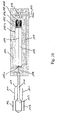
- pressurized fluid F from the inflation/deflation device 213 enters the balloon 203 via the line 214, the channels 216a and 216b and the line 210 ( Figs 15 to 17 ).
- a vacuum is applied in order to purge air from the catheter and the sheath retraction apparatus by means of the inflation/deflation device 213.
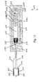
- the unidirectional valve 212 is opened and the unidirectional valve 211 is closed so that space 215a at the distal end of the cylinder 215 at the left-hand side of the piston 205 remains open ( Fig. 12 ).
- pressurized fluid F from the inflation/deflation device 213 enters the space 215a of the cylinder 215 behind the piston 205 via the line 214 and the unidirectional valve 211, while the unidirectional valve 212 and the channels 216a and 216b are closed.
- the piston 205 moves in proximal direction (to the right in Fig. 14 ) and withdraws the protective cover sheath 201 from the stent 202 in the direction of arrows A ( Fig. 14 ).
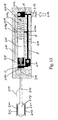
- the piston 205 pushes the valve 207 against the force of the spring 207a into an open position, and the connection between the line 214 and the line 210 via the channels 216a and 216b is opened ( Fig. 15 ).
- pressurized fluid F flows via the line 214, the channels 216a and 216b and the line 210 to the balloon 203.
- the unidirectional valve 211 While the unidirectional valve 211 remains open and pressurized fluid F acts against the piston 205 and pushes it to the right in Fig. 17 , the two-position valve 207 remains in its open position.
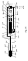
- the balloon 203 expands in the direction of arrows B and the stent is deployed ( Fig. 17 ) and contacts the wall of the blood vessel (not shown). Thereafter, vacuum is again applied from the inflation/deflation device 213 and the balloon 203 deflates in the direction of arrows C ( Fig. 18 ).
- the unidirectional valve 211 is closed and the pressurized fluid behind the piston 205 acts on the piston 205 such that the piston 205 and the sheath 201 remain fixed ( Fig. 18 ). In the final state shown in Fig.
- the catheter is fully purged and the balloon can be re-inflated if necessary.
- the pressurized fluid F holds the two-position valve 207 open and locks the sheath 201 in the retracted position. If the retraction apparatus will be used one time only, it can be removed. If the retraction apparatus will be re-used, the fluid F is purged from the cylinder 215 by opening the unidirectional valve 211 and pulling the piston 205 to the distal end 215a.
- the fluid pressure for operating the retraction device and the expandable means can be controlled in such a manner that the retraction device and the expandable means work concurrently or sequentially, e.g. in order to control the correct position of the stent.
- An operator can easily deploy a stent with a protection sheath simply by activating the inflation/deflation device.
Landscapes
- Health & Medical Sciences (AREA)
- Engineering & Computer Science (AREA)
- Biomedical Technology (AREA)
- Cardiology (AREA)
- Oral & Maxillofacial Surgery (AREA)
- Transplantation (AREA)
- Heart & Thoracic Surgery (AREA)
- Vascular Medicine (AREA)
- Life Sciences & Earth Sciences (AREA)
- Animal Behavior & Ethology (AREA)
- General Health & Medical Sciences (AREA)
- Public Health (AREA)
- Veterinary Medicine (AREA)
- Media Introduction/Drainage Providing Device (AREA)
- Prostheses (AREA)
Claims (11)
- Appareil pour la pose et le déploiement d'un stent expansible (2 ; 102 ; 202) à l'intérieur d'un vaisseau, l'appareil comprenant :(a) un cathéter ayant une extrémité proximale et une extrémité distale,(b) des moyens expansibles (3 ; 103 ; 203) montés au niveau de l'extrémité distale du cathéter et étant expansibles au moyen d'un dispositif de pression de fluide (10, 12- 14; 110, 113-115;210,213,214,216),(c) le stent expansible (2 ; 102 ; 202) étant expansible d'un diamètre de pose à un diamètre de déploiement et étant monté sur le cathéter sur les moyens expansibles (3 ; 103 ; 203),(d) une gaine (1 ; 101 ; 201) étant montée de manière coulissante sur le stent (2 ; 102 ; 202) et étant agencée pour le rétraction afin d'exposer le stent (2 ; 102 ; 202) au moyen d'un dispositif de rétraction (4 - 9, 11, 13-15 ; 104, 105, 113 -115 ; 204, 211, 213 - 215), caractérisé en ce que :(e) le dispositif de pression de fluide (10, 13 - 14 ; 110, 113 - 115 ; 210, 213, 214, 216) est en outre agencé pour faire fonctionner le dispositif de rétraction (4 - 9, 11, 13 - 15 ; 104, 105, 113 - 115 ; 204, 211, 213 - 215) de sorte que les moyens expansibles (3 ; 103 ; 203) sont expansés en réponse à la rétraction de la gaine (1 ; 101 ; 201).
- Appareil selon la revendication 1, dans lequel le dispositif de rétraction comprend un agencement de cylindre - piston (5, 7, 9, 15 ; 105, 115 ; 205, 207, 215) actionné par la pression de fluide.
- Appareil selon la revendication 1 ou 2, comprenant des moyens de commande (7, 5, 11, 12 ; 105, 112 ; 205, 211, 212, 207) pour commander la pression de fluide actionnant le dispositif de rétraction et les moyens expansibles, de manière simultanée ou séquentielle.
- Appareil selon la revendication 2 ou 3, dans lequel un premier piston (5 ; 105 ; 205) de l'agencement de cylindre - piston (5, 7, 15 ; 105, 115 ; 205, 207, 215) est raccordé à la gaine (101 ; 201) via un fil (4 ; 104 ; 204).
- Appareil selon l'une quelconque des revendications 2 à 4, dans lequel l'agencement de cylindre - piston (5, 7, 15 ; 105, 115) comprend une sortie (17 ; 110a) raccordée à une conduite de pression de fluide (16, 10 ; 110) pour appliquer la pression de fluide sur les moyens expansibles (3 ; 103).
- Appareil selon la revendication 5, dans lequel l'agencement de cylindre - piston (5, 7, 15) comprend un second piston flottant (7) pour commander l'ouverture / fermeture de la sortie (17).
- Appareil selon la revendication 5 ou 6, dans lequel pendant la rétraction de la gaine (1), le premier piston (5) ou le second piston (7) ferme la sortie (17), et après la rétraction au moins partielle de la gaine (1), les premier et second pistons (5, 7) sont dans une position au niveau de l'extrémité proximale du cylindre (15) et la sortie (17) est ouverte.
- Appareil selon la revendication 7, dans lequel le premier piston (5) comprend un crochet (6), le second piston (7) comprend une première ouverture centrale (18), le cylindre (15) comprend une seconde ouverture (19) et un support de crochet (8) au niveau de son extrémité proximale, de sorte que pendant la rétraction de la gaine (1), le premier piston qui se décale (5) déplace le crochet (6) à travers la première ouverture (18) et la seconde ouverture (19) jusqu'à ce que le crochet (6) mette en prise le support de crochet (8).
- Appareil selon la revendication 5, dans lequel le premier agencement de piston (105) comprend des moyens de connecteur (106) et le cylindre (115) comprend au niveau de son extrémité proximale, des moyens de réception (108) pour les moyens de connecteur (106), de sorte qu'après la rétraction de la gaine (101), le moyens de connecteur (106) mettent en prise les moyens de réception (108) et la sortie (110a) est raccordée à la pression de fluide agissant sur le premier piston (105).
- Appareil selon la revendication 4, dans lequel l'agencement de cylindre - piston comprend le premier piston (205) et une soupape à deux positions (207) venant en butée, via un ressort (207a) au niveau de l'extrémité proximale (215b) du cylindre (215), dans lequel dans une position fermée, la soupape (207) se ferme par les canaux à ressort (216a, 216b) pénétrant dans la paroi du cylindre (215), et
dans une position ouverte, la soupape (207) ouvre les canaux (216a, 216b) après qu'elle a été poussée par le piston (205) lorsque la gaine (201) est rétractée et raccorde une conduite de pression de fluide (214) à partir du dispositif de pression de fluide (213) avec une conduite de pression de fluide (210) de sorte que la pression de fluide est appliquée sur les moyens expansibles (203). - Appareil selon l'une quelconque des revendications 1 à 10, dans lequel le fluide est du liquide.
Priority Applications (2)
| Application Number | Priority Date | Filing Date | Title |
|---|---|---|---|
| EP10004649A EP2210571A1 (fr) | 2002-08-07 | 2003-08-07 | Dispositif de mise en place et le déploiement d'un stent dans un vaisseau sanguin |
| EP03784199A EP1551336B1 (fr) | 2002-08-07 | 2003-08-07 | Dispositif de mise en place et de deploiement d'un stent gonflable dans un vaisseau sanguin |
Applications Claiming Priority (4)
| Application Number | Priority Date | Filing Date | Title |
|---|---|---|---|
| EP02017696A EP1388328A1 (fr) | 2002-08-07 | 2002-08-07 | Dispositif de mise en place et le déploiement d'un stent dans un vaisseau sanguin |
| EP02017696 | 2002-08-07 | ||
| PCT/EP2003/008795 WO2004014256A1 (fr) | 2002-08-07 | 2003-08-07 | Dispositif de mise en place et de deploiement d'un stent gonflable dans un vaisseau sanguin |
| EP03784199A EP1551336B1 (fr) | 2002-08-07 | 2003-08-07 | Dispositif de mise en place et de deploiement d'un stent gonflable dans un vaisseau sanguin |
Publications (2)
| Publication Number | Publication Date |
|---|---|
| EP1551336A1 EP1551336A1 (fr) | 2005-07-13 |
| EP1551336B1 true EP1551336B1 (fr) | 2010-05-05 |
Family
ID=30129204
Family Applications (3)
| Application Number | Title | Priority Date | Filing Date |
|---|---|---|---|
| EP02017696A Withdrawn EP1388328A1 (fr) | 2002-08-07 | 2002-08-07 | Dispositif de mise en place et le déploiement d'un stent dans un vaisseau sanguin |
| EP03784199A Expired - Lifetime EP1551336B1 (fr) | 2002-08-07 | 2003-08-07 | Dispositif de mise en place et de deploiement d'un stent gonflable dans un vaisseau sanguin |
| EP10004649A Withdrawn EP2210571A1 (fr) | 2002-08-07 | 2003-08-07 | Dispositif de mise en place et le déploiement d'un stent dans un vaisseau sanguin |
Family Applications Before (1)
| Application Number | Title | Priority Date | Filing Date |
|---|---|---|---|
| EP02017696A Withdrawn EP1388328A1 (fr) | 2002-08-07 | 2002-08-07 | Dispositif de mise en place et le déploiement d'un stent dans un vaisseau sanguin |
Family Applications After (1)
| Application Number | Title | Priority Date | Filing Date |
|---|---|---|---|
| EP10004649A Withdrawn EP2210571A1 (fr) | 2002-08-07 | 2003-08-07 | Dispositif de mise en place et le déploiement d'un stent dans un vaisseau sanguin |
Country Status (8)
| Country | Link |
|---|---|
| US (2) | US7875067B2 (fr) |
| EP (3) | EP1388328A1 (fr) |
| JP (1) | JP2005534439A (fr) |
| AT (1) | ATE466544T1 (fr) |
| AU (1) | AU2003260388A1 (fr) |
| CA (1) | CA2493118C (fr) |
| DE (1) | DE60332470D1 (fr) |
| WO (1) | WO2004014256A1 (fr) |
Cited By (15)
| Publication number | Priority date | Publication date | Assignee | Title |
|---|---|---|---|---|
| US8052749B2 (en) | 2003-12-23 | 2011-11-08 | Sadra Medical, Inc. | Methods and apparatus for endovascular heart valve replacement comprising tissue grasping elements |
| US8231670B2 (en) | 2003-12-23 | 2012-07-31 | Sadra Medical, Inc. | Repositionable heart valve and method |
| US8246678B2 (en) | 2003-12-23 | 2012-08-21 | Sadra Medicl, Inc. | Methods and apparatus for endovascularly replacing a patient's heart valve |
| US8252052B2 (en) | 2003-12-23 | 2012-08-28 | Sadra Medical, Inc. | Methods and apparatus for endovascularly replacing a patient's heart valve |
| US8328868B2 (en) | 2004-11-05 | 2012-12-11 | Sadra Medical, Inc. | Medical devices and delivery systems for delivering medical devices |
| US8623078B2 (en) | 2003-12-23 | 2014-01-07 | Sadra Medical, Inc. | Replacement valve and anchor |
| US8623076B2 (en) | 2003-12-23 | 2014-01-07 | Sadra Medical, Inc. | Low profile heart valve and delivery system |
| US8668733B2 (en) | 2004-06-16 | 2014-03-11 | Sadra Medical, Inc. | Everting heart valve |
| US8858620B2 (en) | 2003-12-23 | 2014-10-14 | Sadra Medical Inc. | Methods and apparatus for endovascularly replacing a heart valve |
| US8894703B2 (en) | 2003-12-23 | 2014-11-25 | Sadra Medical, Inc. | Systems and methods for delivering a medical implant |
| US8998976B2 (en) | 2011-07-12 | 2015-04-07 | Boston Scientific Scimed, Inc. | Coupling system for medical devices |
| US9005273B2 (en) | 2003-12-23 | 2015-04-14 | Sadra Medical, Inc. | Assessing the location and performance of replacement heart valves |
| US9011521B2 (en) | 2003-12-23 | 2015-04-21 | Sadra Medical, Inc. | Methods and apparatus for endovascularly replacing a patient's heart valve |
| US9393113B2 (en) | 2003-12-23 | 2016-07-19 | Boston Scientific Scimed Inc. | Retrievable heart valve anchor and method |
| CN110123405A (zh) * | 2019-05-09 | 2019-08-16 | 吉林大学中日联谊医院 | 一种新型血管外科用血管吻合装置 |
Families Citing this family (99)
| Publication number | Priority date | Publication date | Assignee | Title |
|---|---|---|---|---|
| IL154433A0 (en) | 2000-08-18 | 2003-09-17 | Atritech Inc | Expandable implant devices for filtering blood flow from atrial appendages |
| EP1388328A1 (fr) | 2002-08-07 | 2004-02-11 | Abbott Laboratories Vascular Enterprises Limited | Dispositif de mise en place et le déploiement d'un stent dans un vaisseau sanguin |
| US7635382B2 (en) * | 2003-10-22 | 2009-12-22 | Medtronic Vascular, Inc. | Delivery system for long self-expanding stents |
| US8287584B2 (en) | 2005-11-14 | 2012-10-16 | Sadra Medical, Inc. | Medical implant deployment tool |
| US7748389B2 (en) | 2003-12-23 | 2010-07-06 | Sadra Medical, Inc. | Leaflet engagement elements and methods for use thereof |
| US8343213B2 (en) | 2003-12-23 | 2013-01-01 | Sadra Medical, Inc. | Leaflet engagement elements and methods for use thereof |
| US8840663B2 (en) | 2003-12-23 | 2014-09-23 | Sadra Medical, Inc. | Repositionable heart valve method |
| US20050137687A1 (en) | 2003-12-23 | 2005-06-23 | Sadra Medical | Heart valve anchor and method |
| US8579962B2 (en) | 2003-12-23 | 2013-11-12 | Sadra Medical, Inc. | Methods and apparatus for performing valvuloplasty |
| US7824442B2 (en) | 2003-12-23 | 2010-11-02 | Sadra Medical, Inc. | Methods and apparatus for endovascularly replacing a heart valve |
| US20120041550A1 (en) | 2003-12-23 | 2012-02-16 | Sadra Medical, Inc. | Methods and Apparatus for Endovascular Heart Valve Replacement Comprising Tissue Grasping Elements |
| US9526609B2 (en) | 2003-12-23 | 2016-12-27 | Boston Scientific Scimed, Inc. | Methods and apparatus for endovascularly replacing a patient's heart valve |
| US11278398B2 (en) | 2003-12-23 | 2022-03-22 | Boston Scientific Scimed, Inc. | Methods and apparatus for endovascular heart valve replacement comprising tissue grasping elements |
| US7824443B2 (en) | 2003-12-23 | 2010-11-02 | Sadra Medical, Inc. | Medical implant delivery and deployment tool |
| DE102005003632A1 (de) | 2005-01-20 | 2006-08-17 | Fraunhofer-Gesellschaft zur Förderung der angewandten Forschung e.V. | Katheter für die transvaskuläre Implantation von Herzklappenprothesen |
| US8025694B2 (en) | 2005-02-25 | 2011-09-27 | Abbott Laboratories Vascular Enterprises Limited | Modular vascular prosthesis and methods of use |
| US8002818B2 (en) | 2005-02-25 | 2011-08-23 | Abbott Laboratories Vascular Enterprises Limited | Modular vascular prosthesis having axially variable properties and improved flexibility and methods of use |
| US7962208B2 (en) | 2005-04-25 | 2011-06-14 | Cardiac Pacemakers, Inc. | Method and apparatus for pacing during revascularization |
| US7712606B2 (en) | 2005-09-13 | 2010-05-11 | Sadra Medical, Inc. | Two-part package for medical implant |
| US7569071B2 (en) | 2005-09-21 | 2009-08-04 | Boston Scientific Scimed, Inc. | Venous valve, system, and method with sinus pocket |
| US20070213813A1 (en) | 2005-12-22 | 2007-09-13 | Symetis Sa | Stent-valves for valve replacement and associated methods and systems for surgery |
| US8556925B2 (en) * | 2007-10-11 | 2013-10-15 | Vibrynt, Inc. | Devices and methods for treatment of obesity |
| US7896915B2 (en) | 2007-04-13 | 2011-03-01 | Jenavalve Technology, Inc. | Medical device for treating a heart valve insufficiency |
| US9119742B2 (en) * | 2007-07-16 | 2015-09-01 | Cook Medical Technologies Llc | Prosthesis delivery and deployment device |
| US20090275971A1 (en) * | 2007-10-30 | 2009-11-05 | Boston Scientific Scimed, Inc. | Energy activated preloaded detachment mechanisms for implantable devices |
| WO2011104269A1 (fr) | 2008-02-26 | 2011-09-01 | Jenavalve Technology Inc. | Stent pour le positionnement et l'ancrage d'une prothèse valvulaire dans un site d'implantation dans le cœur d'un patient |
| US9044318B2 (en) | 2008-02-26 | 2015-06-02 | Jenavalve Technology Gmbh | Stent for the positioning and anchoring of a valvular prosthesis |
| US8888834B2 (en) | 2008-07-02 | 2014-11-18 | Cook Medical Technologies Llc | Deployment assembly and introducer |
| US10856978B2 (en) | 2010-05-20 | 2020-12-08 | Jenavalve Technology, Inc. | Catheter system |
| WO2011147849A1 (fr) | 2010-05-25 | 2011-12-01 | Jenavalve Technology Inc. | Valvule prothétique et endoprothèse mise en place par cathétérisme comprenant une valvule prothétique et un stent |
| RU139021U1 (ru) | 2010-09-10 | 2014-04-10 | Симетис Са | Устройства для замены клапана, системы, содержащие устройство для замены клапана, устройства для замены сердечного клапана и доставляющая система для доставки устройства для замены сердечного клапана |
| EP4119095A1 (fr) | 2011-03-21 | 2023-01-18 | Cephea Valve Technologies, Inc. | Appareil à soupape basé sur disque |
| EP2520251A1 (fr) | 2011-05-05 | 2012-11-07 | Symetis SA | Procédé et appareil pour compresser des valvules d'endoprothèse |
| US9131926B2 (en) | 2011-11-10 | 2015-09-15 | Boston Scientific Scimed, Inc. | Direct connect flush system |
| US8940014B2 (en) | 2011-11-15 | 2015-01-27 | Boston Scientific Scimed, Inc. | Bond between components of a medical device |
| US8951243B2 (en) | 2011-12-03 | 2015-02-10 | Boston Scientific Scimed, Inc. | Medical device handle |
| US9510945B2 (en) | 2011-12-20 | 2016-12-06 | Boston Scientific Scimed Inc. | Medical device handle |
| US9277993B2 (en) | 2011-12-20 | 2016-03-08 | Boston Scientific Scimed, Inc. | Medical device delivery systems |
| US10172708B2 (en) | 2012-01-25 | 2019-01-08 | Boston Scientific Scimed, Inc. | Valve assembly with a bioabsorbable gasket and a replaceable valve implant |
| US9579198B2 (en) | 2012-03-01 | 2017-02-28 | Twelve, Inc. | Hydraulic delivery systems for prosthetic heart valve devices and associated methods |
| US9271855B2 (en) * | 2012-05-09 | 2016-03-01 | Abbott Cardiovascular Systems Inc. | Catheter having hydraulic actuator with tandem chambers |
| US20130304180A1 (en) | 2012-05-09 | 2013-11-14 | Michael L. Green | Catheter having dual balloon hydraulic actuator |
| US9011513B2 (en) | 2012-05-09 | 2015-04-21 | Abbott Cardiovascular Systems Inc. | Catheter having hydraulic actuator |
| US9883941B2 (en) | 2012-06-19 | 2018-02-06 | Boston Scientific Scimed, Inc. | Replacement heart valve |
| US10531971B2 (en) | 2013-03-12 | 2020-01-14 | Abbott Cardiovascular System Inc. | Balloon catheter having hydraulic actuator |
| US10420662B2 (en) | 2013-03-12 | 2019-09-24 | Abbott Cardiovascular Systems Inc. | Catheter having movable tubular structure and proximal stopper |
| US9283101B2 (en) | 2013-03-12 | 2016-03-15 | Abbott Cardiovascular Systems Inc. | Catheter having hydraulic actuator and locking system |
| US9561103B2 (en) | 2013-07-17 | 2017-02-07 | Cephea Valve Technologies, Inc. | System and method for cardiac valve repair and replacement |
| WO2015028209A1 (fr) | 2013-08-30 | 2015-03-05 | Jenavalve Technology Gmbh | Cadre radialement repliable pour valvule prothétique et procédé de fabrication dudit cadre |
| ES2777225T3 (es) * | 2014-08-27 | 2020-08-04 | Becton Dickinson Holdings Pte Ltd | Aparato de limitación de presión |
| US9901445B2 (en) | 2014-11-21 | 2018-02-27 | Boston Scientific Scimed, Inc. | Valve locking mechanism |
| AU2015361260B2 (en) | 2014-12-09 | 2020-04-23 | Cephea Valve Technologies, Inc. | Replacement cardiac valves and methods of use and manufacture |
| US10449043B2 (en) | 2015-01-16 | 2019-10-22 | Boston Scientific Scimed, Inc. | Displacement based lock and release mechanism |
| US9861477B2 (en) | 2015-01-26 | 2018-01-09 | Boston Scientific Scimed Inc. | Prosthetic heart valve square leaflet-leaflet stitch |
| WO2016126524A1 (fr) | 2015-02-03 | 2016-08-11 | Boston Scientific Scimed, Inc. | Valve cardiaque prothétique à joint tubulaire |
| US9788942B2 (en) | 2015-02-03 | 2017-10-17 | Boston Scientific Scimed Inc. | Prosthetic heart valve having tubular seal |
| US10426617B2 (en) | 2015-03-06 | 2019-10-01 | Boston Scientific Scimed, Inc. | Low profile valve locking mechanism and commissure assembly |
| US10285809B2 (en) | 2015-03-06 | 2019-05-14 | Boston Scientific Scimed Inc. | TAVI anchoring assist device |
| US10080652B2 (en) | 2015-03-13 | 2018-09-25 | Boston Scientific Scimed, Inc. | Prosthetic heart valve having an improved tubular seal |
| EP3270825B1 (fr) | 2015-03-20 | 2020-04-22 | JenaValve Technology, Inc. | Système de pose de prothèse de valvule cardiaque |
| EP3288495B1 (fr) | 2015-05-01 | 2019-09-25 | JenaValve Technology, Inc. | Dispositif à débit réduit de stimulateur cardiaque lors d'un remplacement de valvules cardiaques |
| AU2016262564B2 (en) | 2015-05-14 | 2020-11-05 | Cephea Valve Technologies, Inc. | Replacement mitral valves |
| WO2016183523A1 (fr) | 2015-05-14 | 2016-11-17 | Cephea Valve Technologies, Inc. | Dispositifs et systèmes de mise en place de valve cardiaque |
| WO2018136959A1 (fr) | 2017-01-23 | 2018-07-26 | Cephea Valve Technologies, Inc. | Valves mitrales de remplacement |
| US10335277B2 (en) | 2015-07-02 | 2019-07-02 | Boston Scientific Scimed Inc. | Adjustable nosecone |
| US10195392B2 (en) | 2015-07-02 | 2019-02-05 | Boston Scientific Scimed, Inc. | Clip-on catheter |
| BR112018002720B1 (pt) | 2015-08-11 | 2022-08-23 | Mokita Medical Gmbh I.Gr | Sistemas e métodos para remover o ar de dispositivos médicos |
| US10610394B2 (en) | 2015-08-11 | 2020-04-07 | Mokita Medical Gmbh | Systems and methods for using perfluorocarbons to remove gases from medical devices |
| US10136991B2 (en) | 2015-08-12 | 2018-11-27 | Boston Scientific Scimed Inc. | Replacement heart valve implant |
| US10179041B2 (en) | 2015-08-12 | 2019-01-15 | Boston Scientific Scimed Icn. | Pinless release mechanism |
| US10779940B2 (en) | 2015-09-03 | 2020-09-22 | Boston Scientific Scimed, Inc. | Medical device handle |
| US10342660B2 (en) | 2016-02-02 | 2019-07-09 | Boston Scientific Inc. | Tensioned sheathing aids |
| WO2017195125A1 (fr) | 2016-05-13 | 2017-11-16 | Jenavalve Technology, Inc. | Système d'implantation de prothèse de valve cardiaque et procédé pour la pose d'une prothèse de valve cardiaque avec une gaine d'introduction et système de chargement |
| US10245136B2 (en) | 2016-05-13 | 2019-04-02 | Boston Scientific Scimed Inc. | Containment vessel with implant sheathing guide |
| US10583005B2 (en) | 2016-05-13 | 2020-03-10 | Boston Scientific Scimed, Inc. | Medical device handle |
| US10201416B2 (en) | 2016-05-16 | 2019-02-12 | Boston Scientific Scimed, Inc. | Replacement heart valve implant with invertible leaflets |
| US11331187B2 (en) | 2016-06-17 | 2022-05-17 | Cephea Valve Technologies, Inc. | Cardiac valve delivery devices and systems |
| EP4209196A1 (fr) | 2017-01-23 | 2023-07-12 | Cephea Valve Technologies, Inc. | Valvules mitrales de remplacement |
| US11197754B2 (en) | 2017-01-27 | 2021-12-14 | Jenavalve Technology, Inc. | Heart valve mimicry |
| US10575950B2 (en) | 2017-04-18 | 2020-03-03 | Twelve, Inc. | Hydraulic systems for delivering prosthetic heart valve devices and associated methods |
| US10646338B2 (en) | 2017-06-02 | 2020-05-12 | Twelve, Inc. | Delivery systems with telescoping capsules for deploying prosthetic heart valve devices and associated methods |
| US10828154B2 (en) | 2017-06-08 | 2020-11-10 | Boston Scientific Scimed, Inc. | Heart valve implant commissure support structure |
| EP3661458A1 (fr) | 2017-08-01 | 2020-06-10 | Boston Scientific Scimed, Inc. | Mécanisme de verrouillage d'implant médical |
| CN111225633B (zh) | 2017-08-16 | 2022-05-31 | 波士顿科学国际有限公司 | 置换心脏瓣膜接合组件 |
| WO2019144069A2 (fr) | 2018-01-19 | 2019-07-25 | Boston Scientific Scimed, Inc. | Capteurs de déploiement de mode d'inductance de système de valve transcathéter |
| US11246625B2 (en) | 2018-01-19 | 2022-02-15 | Boston Scientific Scimed, Inc. | Medical device delivery system with feedback loop |
| WO2019157156A1 (fr) | 2018-02-07 | 2019-08-15 | Boston Scientific Scimed, Inc. | Système de pose de dispositif médical avec élément d'alignement |
| EP3758651B1 (fr) | 2018-02-26 | 2022-12-07 | Boston Scientific Scimed, Inc. | Marqueur radio-opaque intégré dans un joint adaptatif |
| WO2019222367A1 (fr) | 2018-05-15 | 2019-11-21 | Boston Scientific Scimed, Inc. | Ensemble commissure de valvule cardiaque de remplacement |
| US10441449B1 (en) | 2018-05-30 | 2019-10-15 | Vesper Medical, Inc. | Rotary handle stent delivery system and method |
| WO2019241477A1 (fr) | 2018-06-13 | 2019-12-19 | Boston Scientific Scimed, Inc. | Dispositif de pose de valvule cardiaque de remplacement |
| US10449073B1 (en) | 2018-09-18 | 2019-10-22 | Vesper Medical, Inc. | Rotary handle stent delivery system and method |
| WO2020123486A1 (fr) | 2018-12-10 | 2020-06-18 | Boston Scientific Scimed, Inc. | Système d'administration de dispositif médical comprenant un élément de résistance |
| US11439504B2 (en) | 2019-05-10 | 2022-09-13 | Boston Scientific Scimed, Inc. | Replacement heart valve with improved cusp washout and reduced loading |
| US11219541B2 (en) | 2020-05-21 | 2022-01-11 | Vesper Medical, Inc. | Wheel lock for thumbwheel actuated device |
| CN115177402B (zh) * | 2021-04-06 | 2025-06-27 | 上海微创心通医疗科技有限公司 | 医疗植入体的输送系统 |
| CN115177417B (zh) * | 2021-04-06 | 2025-05-09 | 上海微创心通医疗科技有限公司 | 用于输送植入体的输送系统 |
| CN117120002A (zh) | 2021-04-09 | 2023-11-24 | 波士顿科学国际有限公司 | 医疗植入物的旋转对准 |
| US12171658B2 (en) | 2022-11-09 | 2024-12-24 | Jenavalve Technology, Inc. | Catheter system for sequential deployment of an expandable implant |
Family Cites Families (19)
| Publication number | Priority date | Publication date | Assignee | Title |
|---|---|---|---|---|
| US3605745A (en) * | 1969-12-15 | 1971-09-20 | Milton Hodosh | Dental injection apparatus |
| US4116201A (en) * | 1976-12-20 | 1978-09-26 | The Kendall Company | Catheter with inflation control device |
| US5113608A (en) | 1987-11-19 | 1992-05-19 | Just One Good Idea | Fishing line connecting system and method of connecting a fishing line to a lure or weight to be moved through the water and components of such a system |
| US5445646A (en) * | 1993-10-22 | 1995-08-29 | Scimed Lifesystems, Inc. | Single layer hydraulic sheath stent delivery apparatus and method |
| JP3566963B2 (ja) * | 1993-10-22 | 2004-09-15 | シメッド ライフ システムズ インコーポレイテッド | 改良されたステント配送装置及び方法 |
| US5571135A (en) * | 1993-10-22 | 1996-11-05 | Scimed Life Systems Inc. | Stent delivery apparatus and method |
| US5817101A (en) * | 1997-03-13 | 1998-10-06 | Schneider (Usa) Inc | Fluid actuated stent delivery system |
| WO2000018330A1 (fr) * | 1998-09-30 | 2000-04-06 | Impra, Inc. | Mecanisme de mise en place d'extenseur implantable |
| US6059813A (en) * | 1998-11-06 | 2000-05-09 | Scimed Life Systems, Inc. | Rolling membrane stent delivery system |
| US6113608A (en) * | 1998-11-20 | 2000-09-05 | Scimed Life Systems, Inc. | Stent delivery device |
| US6168617B1 (en) | 1999-06-14 | 2001-01-02 | Scimed Life Systems, Inc. | Stent delivery system |
| US6702843B1 (en) * | 2000-04-12 | 2004-03-09 | Scimed Life Systems, Inc. | Stent delivery means with balloon retraction means |
| US7163552B2 (en) * | 2000-10-13 | 2007-01-16 | Medtronic Vascular, Inc. | Stent delivery system with hydraulic deployment |
| US6547804B2 (en) * | 2000-12-27 | 2003-04-15 | Scimed Life Systems, Inc. | Selectively permeable highly distensible occlusion balloon |
| US6736839B2 (en) * | 2001-02-01 | 2004-05-18 | Charles Cummings | Medical device delivery system |
| US20030125764A1 (en) * | 2001-06-27 | 2003-07-03 | Eamon Brady | Catheter |
| EP1388328A1 (fr) | 2002-08-07 | 2004-02-11 | Abbott Laboratories Vascular Enterprises Limited | Dispositif de mise en place et le déploiement d'un stent dans un vaisseau sanguin |
| US7613503B2 (en) * | 2002-08-09 | 2009-11-03 | Boston Scientific Scimed, Inc. | Device with infusion holes for imaging inside a blood vessel |
| US20040267110A1 (en) * | 2003-06-12 | 2004-12-30 | Patrice Tremble | Method for detection of vulnerable plaque |
-
2002
- 2002-08-07 EP EP02017696A patent/EP1388328A1/fr not_active Withdrawn
-
2003
- 2003-08-07 EP EP03784199A patent/EP1551336B1/fr not_active Expired - Lifetime
- 2003-08-07 DE DE60332470T patent/DE60332470D1/de not_active Expired - Lifetime
- 2003-08-07 JP JP2004526907A patent/JP2005534439A/ja active Pending
- 2003-08-07 EP EP10004649A patent/EP2210571A1/fr not_active Withdrawn
- 2003-08-07 WO PCT/EP2003/008795 patent/WO2004014256A1/fr not_active Ceased
- 2003-08-07 AT AT03784199T patent/ATE466544T1/de not_active IP Right Cessation
- 2003-08-07 AU AU2003260388A patent/AU2003260388A1/en not_active Abandoned
- 2003-08-07 US US10/523,596 patent/US7875067B2/en not_active Expired - Fee Related
- 2003-08-07 CA CA2493118A patent/CA2493118C/fr not_active Expired - Fee Related
-
2011
- 2011-01-24 US US13/012,587 patent/US8979916B2/en not_active Expired - Fee Related
Cited By (27)
| Publication number | Priority date | Publication date | Assignee | Title |
|---|---|---|---|---|
| US8894703B2 (en) | 2003-12-23 | 2014-11-25 | Sadra Medical, Inc. | Systems and methods for delivering a medical implant |
| US10925724B2 (en) | 2003-12-23 | 2021-02-23 | Boston Scientific Scimed, Inc. | Replacement valve and anchor |
| US8246678B2 (en) | 2003-12-23 | 2012-08-21 | Sadra Medicl, Inc. | Methods and apparatus for endovascularly replacing a patient's heart valve |
| US8252052B2 (en) | 2003-12-23 | 2012-08-28 | Sadra Medical, Inc. | Methods and apparatus for endovascularly replacing a patient's heart valve |
| US11696825B2 (en) | 2003-12-23 | 2023-07-11 | Boston Scientific Scimed, Inc. | Replacement valve and anchor |
| US9532872B2 (en) | 2003-12-23 | 2017-01-03 | Boston Scientific Scimed, Inc. | Systems and methods for delivering a medical implant |
| US8623078B2 (en) | 2003-12-23 | 2014-01-07 | Sadra Medical, Inc. | Replacement valve and anchor |
| US8623076B2 (en) | 2003-12-23 | 2014-01-07 | Sadra Medical, Inc. | Low profile heart valve and delivery system |
| US9393113B2 (en) | 2003-12-23 | 2016-07-19 | Boston Scientific Scimed Inc. | Retrievable heart valve anchor and method |
| US8828078B2 (en) | 2003-12-23 | 2014-09-09 | Sadra Medical, Inc. | Methods and apparatus for endovascular heart valve replacement comprising tissue grasping elements |
| US8840662B2 (en) | 2003-12-23 | 2014-09-23 | Sadra Medical, Inc. | Repositionable heart valve and method |
| US9358110B2 (en) | 2003-12-23 | 2016-06-07 | Boston Scientific Scimed, Inc. | Medical devices and delivery systems for delivering medical devices |
| US8231670B2 (en) | 2003-12-23 | 2012-07-31 | Sadra Medical, Inc. | Repositionable heart valve and method |
| US8052749B2 (en) | 2003-12-23 | 2011-11-08 | Sadra Medical, Inc. | Methods and apparatus for endovascular heart valve replacement comprising tissue grasping elements |
| US8858620B2 (en) | 2003-12-23 | 2014-10-14 | Sadra Medical Inc. | Methods and apparatus for endovascularly replacing a heart valve |
| US9005273B2 (en) | 2003-12-23 | 2015-04-14 | Sadra Medical, Inc. | Assessing the location and performance of replacement heart valves |
| US9011521B2 (en) | 2003-12-23 | 2015-04-21 | Sadra Medical, Inc. | Methods and apparatus for endovascularly replacing a patient's heart valve |
| US9277991B2 (en) | 2003-12-23 | 2016-03-08 | Boston Scientific Scimed, Inc. | Low profile heart valve and delivery system |
| US9308085B2 (en) | 2003-12-23 | 2016-04-12 | Boston Scientific Scimed, Inc. | Repositionable heart valve and method |
| US9320599B2 (en) | 2003-12-23 | 2016-04-26 | Boston Scientific Scimed, Inc. | Methods and apparatus for endovascularly replacing a heart valve |
| US8668733B2 (en) | 2004-06-16 | 2014-03-11 | Sadra Medical, Inc. | Everting heart valve |
| US8992608B2 (en) | 2004-06-16 | 2015-03-31 | Sadra Medical, Inc. | Everting heart valve |
| US8617236B2 (en) | 2004-11-05 | 2013-12-31 | Sadra Medical, Inc. | Medical devices and delivery systems for delivering medical devices |
| US8328868B2 (en) | 2004-11-05 | 2012-12-11 | Sadra Medical, Inc. | Medical devices and delivery systems for delivering medical devices |
| US8998976B2 (en) | 2011-07-12 | 2015-04-07 | Boston Scientific Scimed, Inc. | Coupling system for medical devices |
| CN110123405A (zh) * | 2019-05-09 | 2019-08-16 | 吉林大学中日联谊医院 | 一种新型血管外科用血管吻合装置 |
| CN110123405B (zh) * | 2019-05-09 | 2021-04-30 | 吉林大学中日联谊医院 | 一种新型血管外科用血管吻合装置 |
Also Published As
| Publication number | Publication date |
|---|---|
| US7875067B2 (en) | 2011-01-25 |
| DE60332470D1 (de) | 2010-06-17 |
| JP2005534439A (ja) | 2005-11-17 |
| EP2210571A1 (fr) | 2010-07-28 |
| EP1388328A1 (fr) | 2004-02-11 |
| EP1551336A1 (fr) | 2005-07-13 |
| ATE466544T1 (de) | 2010-05-15 |
| AU2003260388A1 (en) | 2004-02-25 |
| CA2493118A1 (fr) | 2004-02-19 |
| CA2493118C (fr) | 2011-02-01 |
| WO2004014256A1 (fr) | 2004-02-19 |
| US20060142833A1 (en) | 2006-06-29 |
| US8979916B2 (en) | 2015-03-17 |
| US20110160847A1 (en) | 2011-06-30 |
Similar Documents
| Publication | Publication Date | Title |
|---|---|---|
| EP1551336B1 (fr) | Dispositif de mise en place et de deploiement d'un stent gonflable dans un vaisseau sanguin | |
| US6042589A (en) | Reversible-action endoprosthesis delivery device | |
| US6174327B1 (en) | Stent deployment apparatus and method | |
| US10166043B2 (en) | Support apparatus for surgical tube | |
| US5078720A (en) | Stent placement instrument and method | |
| US6113608A (en) | Stent delivery device | |
| US6471672B1 (en) | Selective high pressure dilation balloon | |
| JP3773351B2 (ja) | 流体駆動式ステント供給システム | |
| US5820595A (en) | Adjustable inflatable catheter and method for adjusting the relative position of multiple inflatable portions of a catheter within a body passageway | |
| US4318410A (en) | Double lumen dilatation catheter | |
| US6602226B1 (en) | Low-profile stent delivery system and apparatus | |
| US9119742B2 (en) | Prosthesis delivery and deployment device | |
| WO1998007390B1 (fr) | Systeme d'acheminement d'un stent, dote d'un appareil d'arrimage dudit stent | |
| EP2107331B1 (fr) | Dispositif de lancement de torpilles | |
| JPH10137344A (ja) | ステント供給装置 | |
| JPH10328296A (ja) | 大動脈バルーンポンプのオーバードライブ装置および方法 | |
| SK16932002A3 (sk) | Dvojbalónikový expanzný stent | |
| US10744014B2 (en) | Stent delivery device | |
| AU2756502A (en) | Fluid actuated stent delivery system |
Legal Events
| Date | Code | Title | Description |
|---|---|---|---|
| PUAI | Public reference made under article 153(3) epc to a published international application that has entered the european phase |
Free format text: ORIGINAL CODE: 0009012 |
|
| 17P | Request for examination filed |
Effective date: 20050203 |
|
| AK | Designated contracting states |
Kind code of ref document: A1 Designated state(s): AT BE BG CH CY CZ DE DK EE ES FI FR GB GR HU IE IT LI LU MC NL PT RO SE SI SK TR |
|
| AX | Request for extension of the european patent |
Extension state: AL LT LV MK |
|
| DAX | Request for extension of the european patent (deleted) | ||
| RIN1 | Information on inventor provided before grant (corrected) |
Inventor name: STOPPER, ARMIN Inventor name: BALFE, LOUISE Inventor name: MARX, VOLKER Inventor name: VON OEPEN, RANDOLF Inventor name: COFFEY, LORCAN Inventor name: TROESKEN, VOLKER |
|
| GRAP | Despatch of communication of intention to grant a patent |
Free format text: ORIGINAL CODE: EPIDOSNIGR1 |
|
| GRAS | Grant fee paid |
Free format text: ORIGINAL CODE: EPIDOSNIGR3 |
|
| GRAA | (expected) grant |
Free format text: ORIGINAL CODE: 0009210 |
|
| AK | Designated contracting states |
Kind code of ref document: B1 Designated state(s): AT BE BG CH CY CZ DE DK EE ES FI FR GB GR HU IE IT LI LU MC NL PT RO SE SI SK TR |
|
| REG | Reference to a national code |
Ref country code: GB Ref legal event code: FG4D |
|
| REG | Reference to a national code |
Ref country code: CH Ref legal event code: EP |
|
| REG | Reference to a national code |
Ref country code: IE Ref legal event code: FG4D |
|
| REF | Corresponds to: |
Ref document number: 60332470 Country of ref document: DE Date of ref document: 20100617 Kind code of ref document: P |
|
| REG | Reference to a national code |
Ref country code: NL Ref legal event code: T3 |
|
| PG25 | Lapsed in a contracting state [announced via postgrant information from national office to epo] |
Ref country code: SE Free format text: LAPSE BECAUSE OF FAILURE TO SUBMIT A TRANSLATION OF THE DESCRIPTION OR TO PAY THE FEE WITHIN THE PRESCRIBED TIME-LIMIT Effective date: 20100505 Ref country code: ES Free format text: LAPSE BECAUSE OF FAILURE TO SUBMIT A TRANSLATION OF THE DESCRIPTION OR TO PAY THE FEE WITHIN THE PRESCRIBED TIME-LIMIT Effective date: 20100816 |
|
| PG25 | Lapsed in a contracting state [announced via postgrant information from national office to epo] |
Ref country code: AT Free format text: LAPSE BECAUSE OF FAILURE TO SUBMIT A TRANSLATION OF THE DESCRIPTION OR TO PAY THE FEE WITHIN THE PRESCRIBED TIME-LIMIT Effective date: 20100505 Ref country code: FI Free format text: LAPSE BECAUSE OF FAILURE TO SUBMIT A TRANSLATION OF THE DESCRIPTION OR TO PAY THE FEE WITHIN THE PRESCRIBED TIME-LIMIT Effective date: 20100505 Ref country code: SI Free format text: LAPSE BECAUSE OF FAILURE TO SUBMIT A TRANSLATION OF THE DESCRIPTION OR TO PAY THE FEE WITHIN THE PRESCRIBED TIME-LIMIT Effective date: 20100505 |
|
| REG | Reference to a national code |
Ref country code: CH Ref legal event code: NV Representative=s name: PATENTANWALTSKANZLEI NUECKEL |
|
| PG25 | Lapsed in a contracting state [announced via postgrant information from national office to epo] |
Ref country code: CY Free format text: LAPSE BECAUSE OF FAILURE TO SUBMIT A TRANSLATION OF THE DESCRIPTION OR TO PAY THE FEE WITHIN THE PRESCRIBED TIME-LIMIT Effective date: 20100505 Ref country code: GR Free format text: LAPSE BECAUSE OF FAILURE TO SUBMIT A TRANSLATION OF THE DESCRIPTION OR TO PAY THE FEE WITHIN THE PRESCRIBED TIME-LIMIT Effective date: 20100806 |
|
| PG25 | Lapsed in a contracting state [announced via postgrant information from national office to epo] |
Ref country code: PT Free format text: LAPSE BECAUSE OF FAILURE TO SUBMIT A TRANSLATION OF THE DESCRIPTION OR TO PAY THE FEE WITHIN THE PRESCRIBED TIME-LIMIT Effective date: 20100906 Ref country code: EE Free format text: LAPSE BECAUSE OF FAILURE TO SUBMIT A TRANSLATION OF THE DESCRIPTION OR TO PAY THE FEE WITHIN THE PRESCRIBED TIME-LIMIT Effective date: 20100505 Ref country code: DK Free format text: LAPSE BECAUSE OF FAILURE TO SUBMIT A TRANSLATION OF THE DESCRIPTION OR TO PAY THE FEE WITHIN THE PRESCRIBED TIME-LIMIT Effective date: 20100505 |
|
| PG25 | Lapsed in a contracting state [announced via postgrant information from national office to epo] |
Ref country code: RO Free format text: LAPSE BECAUSE OF FAILURE TO SUBMIT A TRANSLATION OF THE DESCRIPTION OR TO PAY THE FEE WITHIN THE PRESCRIBED TIME-LIMIT Effective date: 20100505 Ref country code: SK Free format text: LAPSE BECAUSE OF FAILURE TO SUBMIT A TRANSLATION OF THE DESCRIPTION OR TO PAY THE FEE WITHIN THE PRESCRIBED TIME-LIMIT Effective date: 20100505 Ref country code: BE Free format text: LAPSE BECAUSE OF FAILURE TO SUBMIT A TRANSLATION OF THE DESCRIPTION OR TO PAY THE FEE WITHIN THE PRESCRIBED TIME-LIMIT Effective date: 20100505 Ref country code: CZ Free format text: LAPSE BECAUSE OF FAILURE TO SUBMIT A TRANSLATION OF THE DESCRIPTION OR TO PAY THE FEE WITHIN THE PRESCRIBED TIME-LIMIT Effective date: 20100505 |
|
| PLBE | No opposition filed within time limit |
Free format text: ORIGINAL CODE: 0009261 |
|
| STAA | Information on the status of an ep patent application or granted ep patent |
Free format text: STATUS: NO OPPOSITION FILED WITHIN TIME LIMIT |
|
| PG25 | Lapsed in a contracting state [announced via postgrant information from national office to epo] |
Ref country code: IT Free format text: LAPSE BECAUSE OF FAILURE TO SUBMIT A TRANSLATION OF THE DESCRIPTION OR TO PAY THE FEE WITHIN THE PRESCRIBED TIME-LIMIT Effective date: 20100505 Ref country code: MC Free format text: LAPSE BECAUSE OF NON-PAYMENT OF DUE FEES Effective date: 20100831 |
|
| 26N | No opposition filed |
Effective date: 20110208 |
|
| REG | Reference to a national code |
Ref country code: DE Ref legal event code: R097 Ref document number: 60332470 Country of ref document: DE Effective date: 20110207 |
|
| PG25 | Lapsed in a contracting state [announced via postgrant information from national office to epo] |
Ref country code: LU Free format text: LAPSE BECAUSE OF NON-PAYMENT OF DUE FEES Effective date: 20100807 Ref country code: BG Free format text: LAPSE BECAUSE OF FAILURE TO SUBMIT A TRANSLATION OF THE DESCRIPTION OR TO PAY THE FEE WITHIN THE PRESCRIBED TIME-LIMIT Effective date: 20100505 Ref country code: HU Free format text: LAPSE BECAUSE OF FAILURE TO SUBMIT A TRANSLATION OF THE DESCRIPTION OR TO PAY THE FEE WITHIN THE PRESCRIBED TIME-LIMIT Effective date: 20101106 |
|
| PG25 | Lapsed in a contracting state [announced via postgrant information from national office to epo] |
Ref country code: TR Free format text: LAPSE BECAUSE OF FAILURE TO SUBMIT A TRANSLATION OF THE DESCRIPTION OR TO PAY THE FEE WITHIN THE PRESCRIBED TIME-LIMIT Effective date: 20100505 |
|
| PG25 | Lapsed in a contracting state [announced via postgrant information from national office to epo] |
Ref country code: BG Free format text: LAPSE BECAUSE OF FAILURE TO SUBMIT A TRANSLATION OF THE DESCRIPTION OR TO PAY THE FEE WITHIN THE PRESCRIBED TIME-LIMIT Effective date: 20100805 |
|
| REG | Reference to a national code |
Ref country code: FR Ref legal event code: PLFP Year of fee payment: 13 |
|
| REG | Reference to a national code |
Ref country code: FR Ref legal event code: PLFP Year of fee payment: 14 |
|
| REG | Reference to a national code |
Ref country code: FR Ref legal event code: PLFP Year of fee payment: 15 |
|
| REG | Reference to a national code |
Ref country code: CH Ref legal event code: PCAR Free format text: NEW ADDRESS: OBERDORFSTRASSE 16, 8820 WAEDENSWIL (CH) |
|
| REG | Reference to a national code |
Ref country code: FR Ref legal event code: PLFP Year of fee payment: 16 |
|
| PGFP | Annual fee paid to national office [announced via postgrant information from national office to epo] |
Ref country code: NL Payment date: 20190730 Year of fee payment: 17 |
|
| PGFP | Annual fee paid to national office [announced via postgrant information from national office to epo] |
Ref country code: IE Payment date: 20190726 Year of fee payment: 17 Ref country code: DE Payment date: 20190715 Year of fee payment: 17 Ref country code: FR Payment date: 20190717 Year of fee payment: 17 |
|
| PGFP | Annual fee paid to national office [announced via postgrant information from national office to epo] |
Ref country code: GB Payment date: 20190728 Year of fee payment: 17 |
|
| PGFP | Annual fee paid to national office [announced via postgrant information from national office to epo] |
Ref country code: CH Payment date: 20190725 Year of fee payment: 17 |
|
| REG | Reference to a national code |
Ref country code: DE Ref legal event code: R119 Ref document number: 60332470 Country of ref document: DE |
|
| REG | Reference to a national code |
Ref country code: CH Ref legal event code: PL |
|
| REG | Reference to a national code |
Ref country code: NL Ref legal event code: MM Effective date: 20200901 |
|
| GBPC | Gb: european patent ceased through non-payment of renewal fee |
Effective date: 20200807 |
|
| PG25 | Lapsed in a contracting state [announced via postgrant information from national office to epo] |
Ref country code: LI Free format text: LAPSE BECAUSE OF NON-PAYMENT OF DUE FEES Effective date: 20200831 Ref country code: CH Free format text: LAPSE BECAUSE OF NON-PAYMENT OF DUE FEES Effective date: 20200831 |
|
| PG25 | Lapsed in a contracting state [announced via postgrant information from national office to epo] |
Ref country code: FR Free format text: LAPSE BECAUSE OF NON-PAYMENT OF DUE FEES Effective date: 20200831 Ref country code: DE Free format text: LAPSE BECAUSE OF NON-PAYMENT OF DUE FEES Effective date: 20210302 |
|
| PG25 | Lapsed in a contracting state [announced via postgrant information from national office to epo] |
Ref country code: IE Free format text: LAPSE BECAUSE OF NON-PAYMENT OF DUE FEES Effective date: 20200807 Ref country code: GB Free format text: LAPSE BECAUSE OF NON-PAYMENT OF DUE FEES Effective date: 20200807 |
|
| PG25 | Lapsed in a contracting state [announced via postgrant information from national office to epo] |
Ref country code: NL Free format text: LAPSE BECAUSE OF NON-PAYMENT OF DUE FEES Effective date: 20200901 |