EP1551340B1 - Expansionsgerät für einstellbares wirbelimplantat - Google Patents
Expansionsgerät für einstellbares wirbelimplantat Download PDFInfo
- Publication number
- EP1551340B1 EP1551340B1 EP03759465A EP03759465A EP1551340B1 EP 1551340 B1 EP1551340 B1 EP 1551340B1 EP 03759465 A EP03759465 A EP 03759465A EP 03759465 A EP03759465 A EP 03759465A EP 1551340 B1 EP1551340 B1 EP 1551340B1
- Authority
- EP
- European Patent Office
- Prior art keywords
- axle
- assembly
- section
- vertebral
- outer casing
- Prior art date
- Legal status (The legal status is an assumption and is not a legal conclusion. Google has not performed a legal analysis and makes no representation as to the accuracy of the status listed.)
- Expired - Lifetime
Links
- 239000007943 implant Substances 0.000 title claims abstract description 51
- 230000000712 assembly Effects 0.000 claims abstract description 22
- 238000000429 assembly Methods 0.000 claims abstract description 22
- 230000007246 mechanism Effects 0.000 claims description 20
- 230000037431 insertion Effects 0.000 abstract 1
- 238000003780 insertion Methods 0.000 abstract 1
- 208000027418 Wounds and injury Diseases 0.000 description 5
- 230000006378 damage Effects 0.000 description 4
- 208000014674 injury Diseases 0.000 description 4
- 206010023509 Kyphosis Diseases 0.000 description 3
- 238000000034 method Methods 0.000 description 3
- 239000011800 void material Substances 0.000 description 3
- 206010058907 Spinal deformity Diseases 0.000 description 2
- 210000000988 bone and bone Anatomy 0.000 description 2
- 230000008733 trauma Effects 0.000 description 2
- 238000011282 treatment Methods 0.000 description 2
- 206010010356 Congenital anomaly Diseases 0.000 description 1
- 206010028980 Neoplasm Diseases 0.000 description 1
- 208000012287 Prolapse Diseases 0.000 description 1
- 208000020339 Spinal injury Diseases 0.000 description 1
- 238000002679 ablation Methods 0.000 description 1
- 230000006835 compression Effects 0.000 description 1
- 238000007906 compression Methods 0.000 description 1
- 230000003247 decreasing effect Effects 0.000 description 1
- 230000007850 degeneration Effects 0.000 description 1
- 201000010099 disease Diseases 0.000 description 1
- 208000037265 diseases, disorders, signs and symptoms Diseases 0.000 description 1
- 238000006073 displacement reaction Methods 0.000 description 1
- 230000000694 effects Effects 0.000 description 1
- 238000002513 implantation Methods 0.000 description 1
- 238000011065 in-situ storage Methods 0.000 description 1
- 238000009434 installation Methods 0.000 description 1
- 210000004705 lumbosacral region Anatomy 0.000 description 1
- 239000000463 material Substances 0.000 description 1
- 238000001356 surgical procedure Methods 0.000 description 1
- 210000000115 thoracic cavity Anatomy 0.000 description 1
- 210000001519 tissue Anatomy 0.000 description 1
- 230000000472 traumatic effect Effects 0.000 description 1
Images


Classifications
-
- A—HUMAN NECESSITIES
- A61—MEDICAL OR VETERINARY SCIENCE; HYGIENE
- A61F—FILTERS IMPLANTABLE INTO BLOOD VESSELS; PROSTHESES; DEVICES PROVIDING PATENCY TO, OR PREVENTING COLLAPSING OF, TUBULAR STRUCTURES OF THE BODY, e.g. STENTS; ORTHOPAEDIC, NURSING OR CONTRACEPTIVE DEVICES; FOMENTATION; TREATMENT OR PROTECTION OF EYES OR EARS; BANDAGES, DRESSINGS OR ABSORBENT PADS; FIRST-AID KITS
- A61F2/00—Filters implantable into blood vessels; Prostheses, i.e. artificial substitutes or replacements for parts of the body; Appliances for connecting them with the body; Devices providing patency to, or preventing collapsing of, tubular structures of the body, e.g. stents
- A61F2/02—Prostheses implantable into the body
- A61F2/30—Joints
- A61F2/46—Special tools for implanting artificial joints
- A61F2/4603—Special tools for implanting artificial joints for insertion or extraction of endoprosthetic joints or of accessories thereof
- A61F2/4611—Special tools for implanting artificial joints for insertion or extraction of endoprosthetic joints or of accessories thereof of spinal prostheses
-
- A—HUMAN NECESSITIES
- A61—MEDICAL OR VETERINARY SCIENCE; HYGIENE
- A61F—FILTERS IMPLANTABLE INTO BLOOD VESSELS; PROSTHESES; DEVICES PROVIDING PATENCY TO, OR PREVENTING COLLAPSING OF, TUBULAR STRUCTURES OF THE BODY, e.g. STENTS; ORTHOPAEDIC, NURSING OR CONTRACEPTIVE DEVICES; FOMENTATION; TREATMENT OR PROTECTION OF EYES OR EARS; BANDAGES, DRESSINGS OR ABSORBENT PADS; FIRST-AID KITS
- A61F2/00—Filters implantable into blood vessels; Prostheses, i.e. artificial substitutes or replacements for parts of the body; Appliances for connecting them with the body; Devices providing patency to, or preventing collapsing of, tubular structures of the body, e.g. stents
- A61F2/02—Prostheses implantable into the body
- A61F2/30—Joints
- A61F2/44—Joints for the spine, e.g. vertebrae, spinal discs
-
- A—HUMAN NECESSITIES
- A61—MEDICAL OR VETERINARY SCIENCE; HYGIENE
- A61F—FILTERS IMPLANTABLE INTO BLOOD VESSELS; PROSTHESES; DEVICES PROVIDING PATENCY TO, OR PREVENTING COLLAPSING OF, TUBULAR STRUCTURES OF THE BODY, e.g. STENTS; ORTHOPAEDIC, NURSING OR CONTRACEPTIVE DEVICES; FOMENTATION; TREATMENT OR PROTECTION OF EYES OR EARS; BANDAGES, DRESSINGS OR ABSORBENT PADS; FIRST-AID KITS
- A61F2/00—Filters implantable into blood vessels; Prostheses, i.e. artificial substitutes or replacements for parts of the body; Appliances for connecting them with the body; Devices providing patency to, or preventing collapsing of, tubular structures of the body, e.g. stents
- A61F2/02—Prostheses implantable into the body
- A61F2/30—Joints
- A61F2/46—Special tools for implanting artificial joints
- A61F2/4603—Special tools for implanting artificial joints for insertion or extraction of endoprosthetic joints or of accessories thereof
-
- A—HUMAN NECESSITIES
- A61—MEDICAL OR VETERINARY SCIENCE; HYGIENE
- A61F—FILTERS IMPLANTABLE INTO BLOOD VESSELS; PROSTHESES; DEVICES PROVIDING PATENCY TO, OR PREVENTING COLLAPSING OF, TUBULAR STRUCTURES OF THE BODY, e.g. STENTS; ORTHOPAEDIC, NURSING OR CONTRACEPTIVE DEVICES; FOMENTATION; TREATMENT OR PROTECTION OF EYES OR EARS; BANDAGES, DRESSINGS OR ABSORBENT PADS; FIRST-AID KITS
- A61F2/00—Filters implantable into blood vessels; Prostheses, i.e. artificial substitutes or replacements for parts of the body; Appliances for connecting them with the body; Devices providing patency to, or preventing collapsing of, tubular structures of the body, e.g. stents
- A61F2/02—Prostheses implantable into the body
- A61F2/30—Joints
- A61F2002/30001—Additional features of subject-matter classified in A61F2/28, A61F2/30 and subgroups thereof
- A61F2002/30108—Shapes
- A61F2002/30199—Three-dimensional shapes
- A61F2002/30224—Three-dimensional shapes cylindrical
- A61F2002/30235—Three-dimensional shapes cylindrical tubular, e.g. sleeves
-
- A—HUMAN NECESSITIES
- A61—MEDICAL OR VETERINARY SCIENCE; HYGIENE
- A61F—FILTERS IMPLANTABLE INTO BLOOD VESSELS; PROSTHESES; DEVICES PROVIDING PATENCY TO, OR PREVENTING COLLAPSING OF, TUBULAR STRUCTURES OF THE BODY, e.g. STENTS; ORTHOPAEDIC, NURSING OR CONTRACEPTIVE DEVICES; FOMENTATION; TREATMENT OR PROTECTION OF EYES OR EARS; BANDAGES, DRESSINGS OR ABSORBENT PADS; FIRST-AID KITS
- A61F2/00—Filters implantable into blood vessels; Prostheses, i.e. artificial substitutes or replacements for parts of the body; Appliances for connecting them with the body; Devices providing patency to, or preventing collapsing of, tubular structures of the body, e.g. stents
- A61F2/02—Prostheses implantable into the body
- A61F2/30—Joints
- A61F2002/30001—Additional features of subject-matter classified in A61F2/28, A61F2/30 and subgroups thereof
- A61F2002/30316—The prosthesis having different structural features at different locations within the same prosthesis; Connections between prosthetic parts; Special structural features of bone or joint prostheses not otherwise provided for
- A61F2002/30329—Connections or couplings between prosthetic parts, e.g. between modular parts; Connecting elements
- A61F2002/30405—Connections or couplings between prosthetic parts, e.g. between modular parts; Connecting elements made by screwing complementary threads machined on the parts themselves
- A61F2002/30411—Connections or couplings between prosthetic parts, e.g. between modular parts; Connecting elements made by screwing complementary threads machined on the parts themselves having two threaded end parts connected by a threaded central part with opposite threads at its opposite ends, i.e. for adjusting the distance between both end parts by rotating the central part
-
- A—HUMAN NECESSITIES
- A61—MEDICAL OR VETERINARY SCIENCE; HYGIENE
- A61F—FILTERS IMPLANTABLE INTO BLOOD VESSELS; PROSTHESES; DEVICES PROVIDING PATENCY TO, OR PREVENTING COLLAPSING OF, TUBULAR STRUCTURES OF THE BODY, e.g. STENTS; ORTHOPAEDIC, NURSING OR CONTRACEPTIVE DEVICES; FOMENTATION; TREATMENT OR PROTECTION OF EYES OR EARS; BANDAGES, DRESSINGS OR ABSORBENT PADS; FIRST-AID KITS
- A61F2/00—Filters implantable into blood vessels; Prostheses, i.e. artificial substitutes or replacements for parts of the body; Appliances for connecting them with the body; Devices providing patency to, or preventing collapsing of, tubular structures of the body, e.g. stents
- A61F2/02—Prostheses implantable into the body
- A61F2/30—Joints
- A61F2002/30001—Additional features of subject-matter classified in A61F2/28, A61F2/30 and subgroups thereof
- A61F2002/30316—The prosthesis having different structural features at different locations within the same prosthesis; Connections between prosthetic parts; Special structural features of bone or joint prostheses not otherwise provided for
- A61F2002/30329—Connections or couplings between prosthetic parts, e.g. between modular parts; Connecting elements
- A61F2002/30518—Connections or couplings between prosthetic parts, e.g. between modular parts; Connecting elements with possibility of relative movement between the prosthetic parts
- A61F2002/30523—Connections or couplings between prosthetic parts, e.g. between modular parts; Connecting elements with possibility of relative movement between the prosthetic parts by means of meshing gear teeth
- A61F2002/30525—Worm gears
-
- A—HUMAN NECESSITIES
- A61—MEDICAL OR VETERINARY SCIENCE; HYGIENE
- A61F—FILTERS IMPLANTABLE INTO BLOOD VESSELS; PROSTHESES; DEVICES PROVIDING PATENCY TO, OR PREVENTING COLLAPSING OF, TUBULAR STRUCTURES OF THE BODY, e.g. STENTS; ORTHOPAEDIC, NURSING OR CONTRACEPTIVE DEVICES; FOMENTATION; TREATMENT OR PROTECTION OF EYES OR EARS; BANDAGES, DRESSINGS OR ABSORBENT PADS; FIRST-AID KITS
- A61F2/00—Filters implantable into blood vessels; Prostheses, i.e. artificial substitutes or replacements for parts of the body; Appliances for connecting them with the body; Devices providing patency to, or preventing collapsing of, tubular structures of the body, e.g. stents
- A61F2/02—Prostheses implantable into the body
- A61F2/30—Joints
- A61F2002/30001—Additional features of subject-matter classified in A61F2/28, A61F2/30 and subgroups thereof
- A61F2002/30316—The prosthesis having different structural features at different locations within the same prosthesis; Connections between prosthetic parts; Special structural features of bone or joint prostheses not otherwise provided for
- A61F2002/30535—Special structural features of bone or joint prostheses not otherwise provided for
- A61F2002/30537—Special structural features of bone or joint prostheses not otherwise provided for adjustable
- A61F2002/3055—Special structural features of bone or joint prostheses not otherwise provided for adjustable for adjusting length
-
- A—HUMAN NECESSITIES
- A61—MEDICAL OR VETERINARY SCIENCE; HYGIENE
- A61F—FILTERS IMPLANTABLE INTO BLOOD VESSELS; PROSTHESES; DEVICES PROVIDING PATENCY TO, OR PREVENTING COLLAPSING OF, TUBULAR STRUCTURES OF THE BODY, e.g. STENTS; ORTHOPAEDIC, NURSING OR CONTRACEPTIVE DEVICES; FOMENTATION; TREATMENT OR PROTECTION OF EYES OR EARS; BANDAGES, DRESSINGS OR ABSORBENT PADS; FIRST-AID KITS
- A61F2/00—Filters implantable into blood vessels; Prostheses, i.e. artificial substitutes or replacements for parts of the body; Appliances for connecting them with the body; Devices providing patency to, or preventing collapsing of, tubular structures of the body, e.g. stents
- A61F2/02—Prostheses implantable into the body
- A61F2/30—Joints
- A61F2002/30001—Additional features of subject-matter classified in A61F2/28, A61F2/30 and subgroups thereof
- A61F2002/30316—The prosthesis having different structural features at different locations within the same prosthesis; Connections between prosthetic parts; Special structural features of bone or joint prostheses not otherwise provided for
- A61F2002/30535—Special structural features of bone or joint prostheses not otherwise provided for
- A61F2002/30593—Special structural features of bone or joint prostheses not otherwise provided for hollow
-
- A—HUMAN NECESSITIES
- A61—MEDICAL OR VETERINARY SCIENCE; HYGIENE
- A61F—FILTERS IMPLANTABLE INTO BLOOD VESSELS; PROSTHESES; DEVICES PROVIDING PATENCY TO, OR PREVENTING COLLAPSING OF, TUBULAR STRUCTURES OF THE BODY, e.g. STENTS; ORTHOPAEDIC, NURSING OR CONTRACEPTIVE DEVICES; FOMENTATION; TREATMENT OR PROTECTION OF EYES OR EARS; BANDAGES, DRESSINGS OR ABSORBENT PADS; FIRST-AID KITS
- A61F2/00—Filters implantable into blood vessels; Prostheses, i.e. artificial substitutes or replacements for parts of the body; Appliances for connecting them with the body; Devices providing patency to, or preventing collapsing of, tubular structures of the body, e.g. stents
- A61F2/02—Prostheses implantable into the body
- A61F2/30—Joints
- A61F2002/30001—Additional features of subject-matter classified in A61F2/28, A61F2/30 and subgroups thereof
- A61F2002/30316—The prosthesis having different structural features at different locations within the same prosthesis; Connections between prosthetic parts; Special structural features of bone or joint prostheses not otherwise provided for
- A61F2002/30535—Special structural features of bone or joint prostheses not otherwise provided for
- A61F2002/30601—Special structural features of bone or joint prostheses not otherwise provided for telescopic
-
- A—HUMAN NECESSITIES
- A61—MEDICAL OR VETERINARY SCIENCE; HYGIENE
- A61F—FILTERS IMPLANTABLE INTO BLOOD VESSELS; PROSTHESES; DEVICES PROVIDING PATENCY TO, OR PREVENTING COLLAPSING OF, TUBULAR STRUCTURES OF THE BODY, e.g. STENTS; ORTHOPAEDIC, NURSING OR CONTRACEPTIVE DEVICES; FOMENTATION; TREATMENT OR PROTECTION OF EYES OR EARS; BANDAGES, DRESSINGS OR ABSORBENT PADS; FIRST-AID KITS
- A61F2/00—Filters implantable into blood vessels; Prostheses, i.e. artificial substitutes or replacements for parts of the body; Appliances for connecting them with the body; Devices providing patency to, or preventing collapsing of, tubular structures of the body, e.g. stents
- A61F2/02—Prostheses implantable into the body
- A61F2/30—Joints
- A61F2/30767—Special external or bone-contacting surface, e.g. coating for improving bone ingrowth
- A61F2/30771—Special external or bone-contacting surface, e.g. coating for improving bone ingrowth applied in original prostheses, e.g. holes or grooves
- A61F2002/30772—Apertures or holes, e.g. of circular cross section
- A61F2002/30784—Plurality of holes
- A61F2002/30787—Plurality of holes inclined obliquely with respect to each other
-
- A—HUMAN NECESSITIES
- A61—MEDICAL OR VETERINARY SCIENCE; HYGIENE
- A61F—FILTERS IMPLANTABLE INTO BLOOD VESSELS; PROSTHESES; DEVICES PROVIDING PATENCY TO, OR PREVENTING COLLAPSING OF, TUBULAR STRUCTURES OF THE BODY, e.g. STENTS; ORTHOPAEDIC, NURSING OR CONTRACEPTIVE DEVICES; FOMENTATION; TREATMENT OR PROTECTION OF EYES OR EARS; BANDAGES, DRESSINGS OR ABSORBENT PADS; FIRST-AID KITS
- A61F2/00—Filters implantable into blood vessels; Prostheses, i.e. artificial substitutes or replacements for parts of the body; Appliances for connecting them with the body; Devices providing patency to, or preventing collapsing of, tubular structures of the body, e.g. stents
- A61F2/02—Prostheses implantable into the body
- A61F2/30—Joints
- A61F2/46—Special tools for implanting artificial joints
- A61F2/4603—Special tools for implanting artificial joints for insertion or extraction of endoprosthetic joints or of accessories thereof
- A61F2002/4622—Special tools for implanting artificial joints for insertion or extraction of endoprosthetic joints or of accessories thereof having the shape of a forceps or a clamp
-
- A—HUMAN NECESSITIES
- A61—MEDICAL OR VETERINARY SCIENCE; HYGIENE
- A61F—FILTERS IMPLANTABLE INTO BLOOD VESSELS; PROSTHESES; DEVICES PROVIDING PATENCY TO, OR PREVENTING COLLAPSING OF, TUBULAR STRUCTURES OF THE BODY, e.g. STENTS; ORTHOPAEDIC, NURSING OR CONTRACEPTIVE DEVICES; FOMENTATION; TREATMENT OR PROTECTION OF EYES OR EARS; BANDAGES, DRESSINGS OR ABSORBENT PADS; FIRST-AID KITS
- A61F2/00—Filters implantable into blood vessels; Prostheses, i.e. artificial substitutes or replacements for parts of the body; Appliances for connecting them with the body; Devices providing patency to, or preventing collapsing of, tubular structures of the body, e.g. stents
- A61F2/02—Prostheses implantable into the body
- A61F2/30—Joints
- A61F2/46—Special tools for implanting artificial joints
- A61F2/4603—Special tools for implanting artificial joints for insertion or extraction of endoprosthetic joints or of accessories thereof
- A61F2002/4625—Special tools for implanting artificial joints for insertion or extraction of endoprosthetic joints or of accessories thereof with relative movement between parts of the instrument during use
- A61F2002/4627—Special tools for implanting artificial joints for insertion or extraction of endoprosthetic joints or of accessories thereof with relative movement between parts of the instrument during use with linear motion along or rotating motion about the instrument axis or the implantation direction, e.g. telescopic, along a guiding rod, screwing inside the instrument
-
- A—HUMAN NECESSITIES
- A61—MEDICAL OR VETERINARY SCIENCE; HYGIENE
- A61F—FILTERS IMPLANTABLE INTO BLOOD VESSELS; PROSTHESES; DEVICES PROVIDING PATENCY TO, OR PREVENTING COLLAPSING OF, TUBULAR STRUCTURES OF THE BODY, e.g. STENTS; ORTHOPAEDIC, NURSING OR CONTRACEPTIVE DEVICES; FOMENTATION; TREATMENT OR PROTECTION OF EYES OR EARS; BANDAGES, DRESSINGS OR ABSORBENT PADS; FIRST-AID KITS
- A61F2/00—Filters implantable into blood vessels; Prostheses, i.e. artificial substitutes or replacements for parts of the body; Appliances for connecting them with the body; Devices providing patency to, or preventing collapsing of, tubular structures of the body, e.g. stents
- A61F2/02—Prostheses implantable into the body
- A61F2/30—Joints
- A61F2/46—Special tools for implanting artificial joints
- A61F2/4603—Special tools for implanting artificial joints for insertion or extraction of endoprosthetic joints or of accessories thereof
- A61F2002/4625—Special tools for implanting artificial joints for insertion or extraction of endoprosthetic joints or of accessories thereof with relative movement between parts of the instrument during use
- A61F2002/4628—Special tools for implanting artificial joints for insertion or extraction of endoprosthetic joints or of accessories thereof with relative movement between parts of the instrument during use with linear motion along or rotating motion about an axis transverse to the instrument axis or to the implantation direction, e.g. clamping
-
- A—HUMAN NECESSITIES
- A61—MEDICAL OR VETERINARY SCIENCE; HYGIENE
- A61F—FILTERS IMPLANTABLE INTO BLOOD VESSELS; PROSTHESES; DEVICES PROVIDING PATENCY TO, OR PREVENTING COLLAPSING OF, TUBULAR STRUCTURES OF THE BODY, e.g. STENTS; ORTHOPAEDIC, NURSING OR CONTRACEPTIVE DEVICES; FOMENTATION; TREATMENT OR PROTECTION OF EYES OR EARS; BANDAGES, DRESSINGS OR ABSORBENT PADS; FIRST-AID KITS
- A61F2/00—Filters implantable into blood vessels; Prostheses, i.e. artificial substitutes or replacements for parts of the body; Appliances for connecting them with the body; Devices providing patency to, or preventing collapsing of, tubular structures of the body, e.g. stents
- A61F2/02—Prostheses implantable into the body
- A61F2/30—Joints
- A61F2/46—Special tools for implanting artificial joints
- A61F2/4637—Special tools for implanting artificial joints for connecting or disconnecting two parts of a prosthesis
- A61F2002/4638—Tools for performing screwing, e.g. nut or screwdrivers, or particular adaptations therefor
-
- A—HUMAN NECESSITIES
- A61—MEDICAL OR VETERINARY SCIENCE; HYGIENE
- A61F—FILTERS IMPLANTABLE INTO BLOOD VESSELS; PROSTHESES; DEVICES PROVIDING PATENCY TO, OR PREVENTING COLLAPSING OF, TUBULAR STRUCTURES OF THE BODY, e.g. STENTS; ORTHOPAEDIC, NURSING OR CONTRACEPTIVE DEVICES; FOMENTATION; TREATMENT OR PROTECTION OF EYES OR EARS; BANDAGES, DRESSINGS OR ABSORBENT PADS; FIRST-AID KITS
- A61F2220/00—Fixations or connections for prostheses classified in groups A61F2/00 - A61F2/26 or A61F2/82 or A61F9/00 or A61F11/00 or subgroups thereof
- A61F2220/0025—Connections or couplings between prosthetic parts, e.g. between modular parts; Connecting elements
-
- A—HUMAN NECESSITIES
- A61—MEDICAL OR VETERINARY SCIENCE; HYGIENE
- A61F—FILTERS IMPLANTABLE INTO BLOOD VESSELS; PROSTHESES; DEVICES PROVIDING PATENCY TO, OR PREVENTING COLLAPSING OF, TUBULAR STRUCTURES OF THE BODY, e.g. STENTS; ORTHOPAEDIC, NURSING OR CONTRACEPTIVE DEVICES; FOMENTATION; TREATMENT OR PROTECTION OF EYES OR EARS; BANDAGES, DRESSINGS OR ABSORBENT PADS; FIRST-AID KITS
- A61F2230/00—Geometry of prostheses classified in groups A61F2/00 - A61F2/26 or A61F2/82 or A61F9/00 or A61F11/00 or subgroups thereof
- A61F2230/0063—Three-dimensional shapes
- A61F2230/0069—Three-dimensional shapes cylindrical
Definitions
- the present invention concerns medical instruments used during surgery. More particularly, a novel apparatus is provided for adjusting an adjustable vertebral implant.
- spinal deformity involves a prolapse of the vertebral column towards the front of the body, often caused by the destruction of the vertebral body itself. This destruction can be in the form of a trauma type injury, such as a fracture or burst injury to the vertebral body, or a non-traumatic deformity caused by a tumor or a degeneration of the bone in the vertebral body.
- Treatment of a kyphosis in the thoracic or lumbar spine appears now to be best achieved through an anterior approach, particularly in order to avoid some of the more severe complications associated with support or replacement of a damaged vertebral body.
- a high degree of anterior reconstruction of the spine is required, most frequently involving total removal of the damaged vertebral body.
- partial or total ablation of the vertebral body and the two adjacent vertebral discs is carried out.
- a vertebral implant assembly may be used to restore the vertebral column to the correct orientation.
- One implant that may be used is disclosed in U.S. Patent No. 6,344,057 to Rabbe et al. ("Rabbe patent").
- the implant disclosed in the Rabbe patent is an adjustable vertebral implant assembly configured to span the void created by the removed vertebral body and discs.
- the assembly includes a thin-walled tubular body which defines a hollow interior and further includes endplates with end surfaces configured to engage the tubular body between the adjacent vertebrae.
- the end surfaces define a bore through the endplate.
- Current surgical spinal reconstruction techniques can use a plurality of wrenches to expand or otherwise manipulate rotationally adjustable implants, such as the assembly disclosed in the Rabbe patent.
- a wrench requires lateral translation which, in the confined area of the wound, can require an enlarged wound and increased labor and time. It must also relocate and reattach to the implant after each turn, which is both difficult and time consuming.
- US 6,190,414 discloses a prosthetic implant and displacement member for displacing the engaging plates to support adjacent vertebrae, and having a gear mechanism.
- US 2002/082695 discloses a setting tool for setting a vertebral implant, also having a gear mechanism.
- the present invention provides an apparatus for installing a vertebral implant assembly, having a tubular body and a pair of endplate assemblies, between two vertebral endplates, the apparatus comprising: an axle having a proximal end and a distal end; a set of gears connected to the proximal end of the axle; and an engager device (58) connected to the set of gears and adapted to rotate the tubular body when the axle is rotated, and wherein, in use, the rotation of the tubular body expands the vertebral implant assembly; characterized by a plurality of gears selectively engaged with the axle.
- the engager device comprises a toothed section configured to engage apertures on the vertebral implant assembly.
- the engager device comprises a positioning mechanism for at least partially surrounding the vertebral implant assembly.
- the apparatus further comprises a holding instrument to resist movement of the vertebral implant assembly during expansion.
- a vertebral column 10 includes a damaged vertebra 12a (shown in phantom) extending between a vertebra 12b and a vertebra 12c.
- An intervertebral disc 14a (shown in phantom) extends between vertebrae 12a and 12b, and an intervertebral disc 14b (shown in phantom) extends between vertebrae 12a and 12c.
- the vertebra 12a can be removed together with discs 14a and 14b creating a void between the two intact vertebra 12b and 12c. This procedure may be performed using an anterior, anterolateral, or other approach known to one skilled in the art.
- a vertebral implant assembly 20 as described in the Rabbe patent can then be provided to fill the void between the two intact vertebrae 12b and 12c.
- the implant assembly 20 generally includes a threaded tubular body 22 extending between threaded endplate assemblies 24 and 26.
- the threaded tubular body 22 is provided with a plurality of apertures 28 that may be used for installation of the assembly 20 and that may also provide an avenue for bone or tissue ingrowth to further enhance the stability of the replacement assembly after implantation.
- the opposite ends of the tubular body 22 are formed into external threads 30.
- the threads 30 may extend from each opposite end over most or all of the length of the tubular body 22 and may be configured to threadedly engage endplate assemblies 24 and 26.
- the endplate assembly 24 may include a flange 32, which may cover a substantial load-bearing area of the endplates of the adjacent intact vertebral bodies.
- a cylinder 34 may be integrally formed with flange 32 to extend toward the threaded tubular body 22 when the endplate assembly 24 is placed within the excised vertebral space.
- the cylinder 34 and flange 32 define a bore 36 there through.
- the inside surface of the bore 36 is provided with internal threads 38 which are configured to mate with the external threads 30 of the tubular body 22.
- the threads 38 extend along the entire length of the cylinder 34 and into the flange 32.
- Endplate assembly 26 may be configured similar or identical to endplate assembly 24 and therefore will not be described in detail.
- the endplate assemblies 24 and 26 may further include one or more apertures 40 configured to engage a holding instrument (as described below for Figs. 6a and 6b ).
- the external threads 30 on the threaded tubular body 22 may be cut in opposite directions (e.g., right handed and left handed) so that the endplates can be drawn together or apart by rotating only the body.
- the threads 30 at each of the ends engage the internal threads 38 of each of the end caps 24 and 26 in the proper direction to draw the end caps together.
- the handedness of the threads 30 can be the same at each end so that it is necessary to individually thread each end cap in opposite directions onto the tubular body 22.
- the assembly 20 may be inserted into the vertebral column (as shown in Fig. 1 ) and then expanded to achieve the desired fit and alignment between the adjacent intact vertebrae.
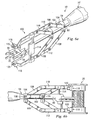
- expansion of the assembly can be achieved by rotating the tubular body 22 using an expander apparatus 50 as shown in Fig. 3 .
- the expander apparatus 50 includes a handle section 52, an extension section 54, a main gear box 56 and an engager 58.
- the expander apparatus 50 may allow the assembly 20 to be adjusted without the use of lateral movement, thereby reducing the size of a patient's wound and decreasing the time and labor involved to complete the procedure. Referring to both Fig. 3 and Fig.
- the handle section 52 can receive and enclose a portion of the extension section 54.
- the extension section 54 may comprise an outer casing 60 through which an interior axle 62 may extend.
- the handle section 52 may include a handle 64 that receives, surrounds and rotationally engages the outer casing 60 of the extension section 54 through one or more bushings 66. It is understood that in other embodiments, the rotational engagement of the outer casing 60 may be accomplished using ball bearing assemblies and/or the material comprising the handle 64.
- the handle 64 may be separated into two independent portions, with one portion being fixed to the outer casing 60 to secure and position the expander apparatus 50 during use, and the other portion being free to rotate for providing the rotational force discussed below.
- the handle section 52 may further include a distally located selector gear box 70.
- the selector gear box 70 may include a set or plurality of gears 72a, 72b, 72c configured to selectively engage with the distal end of the interior axle 62 of the extension section 54.
- Each of the gears 72a, 72b, and 72c may be of a different size so that a user of the expander apparatus 50 may choose from a range of selectable gear ratios, enabling the user to achieve a desired speed or torque for adjusting the vertebral implant assembly 20.
- the selector gear box 70 may be configured to engage with a cap member 74.
- the cap member 74 can be both axially and rotationally movable about the handle 64 and can further include a gear selection member 76 which, as the cap member 74 is moved, can engage any of the different gears 72a, 72b, or 72c to create the desired gear ratio.
- the present embodiment depicts three gears, it is understood that in other embodiments a fewer or a greater number of gears may be used. Further, any of a variety of gear train systems may be employed incorporating a variety of gear components such as a planetary gear system , a layshaft, a clutch, a worm gear system, a bevel gear system, a rack and pinion system, or other gear based systems.
- the cap member 74 rotates or translates about the handle 64 to select a particular gear, but other gear selection mechanisms can also be used.
- the selector gear box may not be located in the handle section 52, but rather, may be included in the extension section 54 or elsewhere in the expander tool 50.
- the selector gear box 70 may be omitted and the distal end of the axle 62 may be fixedly engaged with the gear selection cap 74 and/or a rotating portion of the handle section 52.
- the rotation of the axle 62 may be directly driven by rotation of the gear selection cap 74.
- the axle 62 may be driven by a motor coupled to the axle 62 or to the selector gear box 70.
- the main gear box 56 may include a main gear/tooth assembly 80 and a secondary gear assembly 82.
- the main gear/tooth assembly 80 can be partially enclosed and secured within a casing 83, and can include a gear section 84 coaxially attached to a toothed section 86.
- the casing 83 may include a pin 88 about which the main gear/tooth assembly 80 can rotate.
- the rotational axis of the pin 88 and the gear section 84 may be aligned perpendicular to the rotational axis of the axel 62, although different embodiments may have different arrangements.
- the secondary gear assembly 82 may be attached to the proximate end of the interior axle 62, opposite from the end engaged with the selector gear box 70, and may rotate about the axis of the axle 62.
- the secondary gear assembly 82 may engage with the gear section 84 of the main gear/tooth assembly 80 causing any rotational force from the axle 62 to be transferred to the main gear/tooth assembly 80.
- the main gear box 56 can be further connected to the engager 58.
- the casing 83 of the main gear box 56 may be attached to a positioning mechanism 90, which in the embodiment of Fig. 2 is shaped like a semi-circle with opposing arc portions 92a and 92b.
- the arc portions 92a and 92b can define a cross-section of an engagement area 91 into which the implant assembly 20 may be positioned.
- the positioning mechanism 90 is shaped to mate with the tubular body 22 of the implant assembly 20, allowing the tubular body 22 to rotate while assisting in maintaining the general position and proximity of the engager 58 to the tubular body 22.
- the casing 83 may cover only a portion of the main gear/tooth assembly 80.
- the other portion which can include the tooth section 86, may extend into the engagement area 91 of the engager 58.
- the tooth section 86 may include a plurality of teeth 93 that are sized, spaced, and shaped to engage the apertures 28 on the tubular body 22 when the tubular body 22 is positioned in the engagement area 91.
- the positioning mechanism 90 and the arrangement of the apertures 28 can minimize any translation of the tubular body 22, ensuring that the next tooth 93 easily locates and engages the next aperture 28, to thereby maintain the rotation.
- the teeth 93 are radially arranged on the tooth section 86 in a gear-like configuration.
- a toothed belt or another gripping mechanism can be used to drive the rotation of the tubular body 22.
- the positioning mechanism 90 is shaped more like a "C.” In these embodiments, the positioning mechanism 90 also helps to prevent the engager 58 from accidentally disengaging from the replacement assembly 20.
- the opposing arc portions 92a, 92b are selectively pivotable about pins 94a and 94b with friction keeping the arc portions 92a, 92b either open or closed. In the open position, the tubular body 22 can be positioned in or removed from the engagement area 91. In the closed position, the arc portions 92a and 92b aid in keeping the positioning mechanism 90 engaged to the tubular body 22 while the body rotates. It is understood, that other embodiments may use a clip, a spring, or some other means of engagement to selectively allow the positioning mechanism 90 to remain engaged.
- the positioning mechanism 90 may be configured to more securely maintain the desired position of implant assembly 20.
- the positioning mechanism 90 may extend laterally along the tubular body 22 to restrain the assembly 20 from pivoting about its longitudinal axis.
- Another example e.g. FIG. 6a and 6b ) may include a second positioning mechanism 90 extending from the casing 83 in which case the assembly 20 can be held in position by arc positions both above and below the tooth section 86.
- the expander apparatus 50 may be positioned within the surgical area proximate to the implant assembly 20. It is understood, however, that in some instances the expander apparatus 50 can be used to facilitate the placement of the assembly 20 inside the vertebral column 10.
- the expander apparatus 50 is positioned so that the engager 58 is engaged with the tubular body 22 of the implant assembly 20. Specifically, at least one of the teeth 93 may engage one of the apertures 28.
- the handle 60 can extend away from the vertebral column 10, for example, in an anterior surgical approach, the handle may be positioned in the anterior area of the patient, within easy reach of the surgeon.
- the surgeon can rotate or axially translate the cap member 74 to engage the appropriate gear 72a, 72b, 72c to achieve the desired gear ratio.
- the surgeon can then turn either the handle 64 or the rotatably movable portion of the handle 64 around the axis of the interior axle 62 to expand (or contract, if necessary) the implant assembly 20.
- the rotation of the handle 64 or handle portion is transferred through the gear box 70 to rotate the axle 62.
- the axle rotates the secondary gear assembly 82, which rotates the gear section 84.
- the rotation of the gear section 84 causes the fixedly attached tooth section 86 to rotate which, in turn moves the teeth 93.
- a holding instrument 100 may be coupled to the expander apparatus 50 to hold the implant assembly 20 in position during the expansion, all the while minimizing backlash or lateral movement of the assembly 20.
- the holding instrument can be attached to the extension section 54 by an attachment device 102 which may include one or more rings 104 configured for fastening to the outer casing 60.
- the one or more rings 104 may be fixedly attached to the extension section with one or more fastening mechanisms 106 which can be, for example, screws.
- the fastening mechanisms 106 may engage a protrusion (not shown) extending from the outer casing 60.
- a plurality of expansion members 108 may connect the attachment device 102 to a pair of alignment arms 110 and 112.
- Each expansion member 108 may be a rigid bar pivotally connected at one end to the attachment device 102 and at the opposite end to one of the alignment arms 110 or 112.
- the expansion member may be a spring, an elastic member, or another mechanism capable of expanding with the alignment arms 110 and 112 as the implant 20 is expanded.
- An alignment member 114 may further extend between the alignment arms 110 and 112 and may be adjustable to maintain a relatively parallel alignment of the alignment arms.
- Each of the alignment arms 110 and 112 extend toward the engagement area 91 where the ends of each alignment arm 110 and 112 are configured with holding assemblies 116 and 118, respectively.
- the holding assemblies 116 and 118 may be arc-shaped to accept the assembly 20 and may further include fasteners 120 for engaging the apertures 40 on the endplate assemblies 24 and 26 to maintain the assembly 20 in a generally rigid vertical position while the assembly 20 is expanded.
- the fasteners may be, for example, pins, screws, or clamps.
- the holding assemblies 116 and 118 may fasten to the endplate assemblies 24 and 26 without engaging the apertures 40.
- the expander apparatus 50 with the attached holding instrument 100 may be positioned within the surgical area proximate to the implant assembly 20. It is understood, however, that in some instances the expander apparatus 50 and holding instrument 100 can be used to facilitate the placement of the assembly 20 inside the vertebral column 10.
- the expander apparatus 50 is positioned so that the engager 58 is engaged with the tubular body 22 of the implant assembly 20. Specifically, at least one of the teeth 93 may engage one of the apertures 28.
- the pins 120 may be engaged with the apertures 40 on the endplate assemblies 24 and 26.
- the handle 60 can extend away from the vertebral column 10, for example, in an anterior surgical approach, the handle may be positioned in the anterior area of the patient, within easy reach of the surgeon.
- the surgeon can rotate or axially translate the cap member 74 to engage the appropriate gear 72a, 72b, 72c to achieve the desired gear ratio.
- the surgeon can then rotate either the handle 64 or the rotatably movable portion of the handle 64 along the axis of the interior axle 62 to expand (or contract, if necessary) the implant assembly 20.
- the rotation of the handle 64 or handle portion is transferred through the gear box 70 to rotate the axle 62.
- the axle rotates the secondary gear assembly 82, which rotates the gear section 84.
- the rotation of the gear section 84 causes the fixedly attached tooth section 86 to rotate which, in turn moves the teeth 93.
- the movement of the teeth 93 can cause the tubular body 20 to rotate, which in turn can cause the endplate assemblies 24 and 26 to move relative to one another, thereby expanding (or contracting, if necessary) the implant assembly 20.
- the expansion members 108 may pivot to allow the alignment arms 110 and 112 to move apart while remaining in relatively parallel alignment.
- the alignment member 114 may adjust to further preserve the parallel alignment of the alignment arms 110 and 112.
Landscapes
- Health & Medical Sciences (AREA)
- Engineering & Computer Science (AREA)
- Biomedical Technology (AREA)
- Orthopedic Medicine & Surgery (AREA)
- Transplantation (AREA)
- Oral & Maxillofacial Surgery (AREA)
- Cardiology (AREA)
- Neurology (AREA)
- Heart & Thoracic Surgery (AREA)
- Vascular Medicine (AREA)
- Life Sciences & Earth Sciences (AREA)
- Animal Behavior & Ethology (AREA)
- General Health & Medical Sciences (AREA)
- Public Health (AREA)
- Veterinary Medicine (AREA)
- Physical Education & Sports Medicine (AREA)
- Prostheses (AREA)
- Heating, Cooling, Or Curing Plastics Or The Like In General (AREA)
Claims (11)
- Vorrichtung zum Installieren einer einen rohrförmigen Körper (22) und ein Paar von Endplatten-Einrichtungen (24, 26) aufweisenden Wirbelimplantat-Einrichtung zwischen zwei Wirbel-Endplatten, wobei die Vorrichtung aufweist:eine Achse (62) mit einem proximalen Ende und einem distalen Ende,einen Satz von Zahnrädern (80, 82), die mit dem proximalen Ende der Welle verbunden sind, undeine Eingriffsvorrichtung (58), die mit dem Zahnradsatz verbunden und eingerichtet ist, den rohrförmigen Körper zu drehen, wenn die Welle gedreht wird, undwobei im Gebrauch das Drehen des rohrförmigen Körpers die Wirbelimplantat-Einrichtung erweitert, gekennzeichnet durch eine Mehrzahl von Zahnrädern (70, 72a, b, c), die selektiv mit der Welle in Eingriff sind.
- Vorrichtung gemäß Anspruch 1, ferner aufweisend:ein äußeres Gehäuse (60) undeinen Griff-Abschnitt (52), der mit dem distalen Ende der Welle verbunden ist,wobei sich die Welle durch das äußere Gehäuse hindurch und zumindest teilweise in den Griff hinein erstreckt.
- Vorrichtung gemäß Anspruch 2, wobei der Griff-Abschnitt drehbar mit dem äußeren Gehäuse in Eingriff ist.
- Vorrichtung gemäß Anspruch 2, wobei der Griff-Abschnitt aufweist: einen ersten Abschnitt, der an dem äußeren Gehäuse fixiert ist, und einen zweiten Abschnitt, der geeignet ist, um die Welle zu drehen.
- Vorrichtung gemäß Anspruch 1, ferner ein Kappen-Element (74) aufweisend, das um den Griff-Abschnitt bewegbar ist, wobei das Kappen-Element geeignet ist, um eines oder mehrere aus der Mehrzahl von Zahnrädern auszuwählen, um mit der Welle in Eingriff zu sein.
- Vorrichtung gemäß einem der vorhergehenden Ansprüche, wobei die Eingriffsvorrichtung einen Zahnabschnitt aufweist, der eingerichtet ist, um im Gebrauch in Öffnungen an der Wirbelimplantat-Einrichtung einzugreifen.
- Vorrichtung gemäß Anspruch 1, wobei die Eingriffsvorrichtung einen Positionier-Mechanismus aufweist, um im Gebrauch zumindest teilweise die Wirbelimplantat-Einrichtung zu umgeben.
- Vorrichtung gemäß Anspruch 7, wobei der Positionier-Mechanismus ein Paar von selektiv schwenkbaren Bogenabschnitten aufweist.
- Vorrichtung gemäß Anspruch 6, 7 oder 8, wobei der Zahnradsatz aufweist:eine sekundäre Zahnrad-Einrichtung (82), die an der Welle angebracht ist, undeinen Zahnradabschnitt (84), der an dem Zahnabschnitt angebracht ist,wobei die sekundäre Zahnrad-Einrichtung mit dem ZahnradAbschnitt in Eingriff ist, um die Drehung der Welle in eine Drehung des Zahnabschnitts zu übertragen.
- Vorrichtung gemäß Anspruch 1, ferner aufweisend:ein äußeres Gehäuse, durch das sich die Welle erstreckt, undein an den Endplatten-Einrichtungen der Wirbelimplantat-Einrichtung anzubringendes und ferner an dem äußeren Gehäuse angebrachtes Halte-Instrument.
- Vorrichtung gemäß Anspruch 10, wobei das Halte-Instrument ferner aufweist:ein Paar von parallelen Ausrichtungs-Armen (110, 112) für das Anbringen an den Endplatten-Einrichtungen,eine Anbringungs-Vorrichtung (102) für das Anbringen an dem äußeren Gehäuse,ein oder mehrere Expansions-Elemente (108), die sich zwischen der Anbringungs-Vorrichtung und jedem Ausrichtungs-Arm erstrecken, undein Ausrichtungs-Element (114), das sich zwischen den Ausrichtungs-Armen erstreckt, um die parallele Ausrichtung der Ausrichtungs-Arme zu halten, wenn die Wirbelimplantat-Einrichtung expandiert.
Applications Claiming Priority (3)
| Application Number | Priority Date | Filing Date | Title |
|---|---|---|---|
| US41273002P | 2002-09-23 | 2002-09-23 | |
| US412730P | 2002-09-23 | ||
| PCT/US2003/030018 WO2004026157A2 (en) | 2002-09-23 | 2003-09-20 | Expansion apparatus for adjustable spinal implant |
Publications (2)
| Publication Number | Publication Date |
|---|---|
| EP1551340A2 EP1551340A2 (de) | 2005-07-13 |
| EP1551340B1 true EP1551340B1 (de) | 2008-12-17 |
Family
ID=32030926
Family Applications (1)
| Application Number | Title | Priority Date | Filing Date |
|---|---|---|---|
| EP03759465A Expired - Lifetime EP1551340B1 (de) | 2002-09-23 | 2003-09-20 | Expansionsgerät für einstellbares wirbelimplantat |
Country Status (7)
| Country | Link |
|---|---|
| US (3) | US7588573B2 (de) |
| EP (1) | EP1551340B1 (de) |
| AT (1) | ATE417580T1 (de) |
| AU (1) | AU2003275196A1 (de) |
| CA (1) | CA2500326A1 (de) |
| DE (1) | DE60325401D1 (de) |
| WO (1) | WO2004026157A2 (de) |
Families Citing this family (102)
| Publication number | Priority date | Publication date | Assignee | Title |
|---|---|---|---|---|
| US7291173B2 (en) * | 2003-05-06 | 2007-11-06 | Aesculap Ii, Inc. | Artificial intervertebral disc |
| DE10357926B3 (de) * | 2003-12-11 | 2005-09-01 | Deltacor Gmbh | Längenverstellbares Wirbelsäulen-Implantat |
| DE102004043995A1 (de) * | 2004-09-08 | 2006-03-30 | Aesculap Ag & Co. Kg | Chirurgisches Instrument |
| WO2006044428A2 (en) * | 2004-10-14 | 2006-04-27 | Inventio Llc | Endoscopic multiple biopsy forceps with swing member |
| EP1652479B1 (de) * | 2004-10-27 | 2008-02-20 | BrainLAB AG | Wirbelspreizinstrument mit Markern |
| US8597360B2 (en) | 2004-11-03 | 2013-12-03 | Neuropro Technologies, Inc. | Bone fusion device |
| US20060149284A1 (en) * | 2004-12-15 | 2006-07-06 | Sdgi Holdings, Inc. | Insertion device and method for inserting a member within the body |
| US7942903B2 (en) | 2005-04-12 | 2011-05-17 | Moskowitz Ahmnon D | Bi-directional fixating transvertebral body screws and posterior cervical and lumbar interarticulating joint calibrated stapling devices for spinal fusion |
| US11903849B2 (en) | 2005-04-12 | 2024-02-20 | Moskowitz Family Llc | Intervertebral implant and tool assembly |
| US7811327B2 (en) * | 2005-04-21 | 2010-10-12 | Globus Medical Inc. | Expandable vertebral prosthesis |
| KR20090007690A (ko) * | 2006-03-22 | 2009-01-20 | 알파스파인, 아이엔씨. | 피벗 회전 가능한 내부 몸통 스페이서 |
| US8657882B2 (en) | 2006-04-24 | 2014-02-25 | Warsaw Orthopedic, Inc. | Expandable intervertebral devices and methods of use |
| US7758648B2 (en) * | 2006-04-27 | 2010-07-20 | Warsaw Orthopedic, Inc. | Stabilized, adjustable expandable implant and method |
| US8187331B2 (en) | 2006-04-27 | 2012-05-29 | Warsaw Orthopedic, Inc. | Expandable vertebral implant and methods of use |
| US7794501B2 (en) | 2006-04-27 | 2010-09-14 | Wasaw Orthopedic, Inc. | Expandable intervertebral spacers and methods of use |
| US7914581B2 (en) | 2006-04-27 | 2011-03-29 | Warsaw Orthopedic, Inc. | Expandable implant, instrument, and method |
| US7981157B2 (en) * | 2006-04-27 | 2011-07-19 | Warsaw Orthopedic, Inc. | Self-contained expandable implant and method |
| US7575601B2 (en) * | 2006-04-27 | 2009-08-18 | Warsaw Orthopedic, Inc. | Locking expandable implant and method |
| US7879096B2 (en) | 2006-04-27 | 2011-02-01 | Warsaw Orthopedic, Inc. | Centrally driven expandable implant |
| US7708779B2 (en) | 2006-05-01 | 2010-05-04 | Warsaw Orthopedic, Inc. | Expandable intervertebral spacers and methods of use |
| CA2697784A1 (en) * | 2006-07-07 | 2008-01-10 | Bioassets Development Corporation | Novel regimens for treating diseases and disorders |
| US8062303B2 (en) | 2006-08-16 | 2011-11-22 | K2M, Inc. | Apparatus and methods for inserting an implant |
| WO2008033457A2 (en) * | 2006-09-14 | 2008-03-20 | The University Of Toledo | Variable height vertebral body replacement implant |
| CN101631516A (zh) | 2007-03-13 | 2010-01-20 | 新特斯有限责任公司 | 可调节椎间植入物 |
| WO2008121312A2 (en) | 2007-03-29 | 2008-10-09 | Life Spine, Inc. | Height adjustable spinal prostheses |
| US12539219B2 (en) | 2007-08-21 | 2026-02-03 | Moskowitz Family Llc | Intervertebral implant and tool assembly |
| US8142441B2 (en) * | 2008-10-16 | 2012-03-27 | Aesculap Implant Systems, Llc | Surgical instrument and method of use for inserting an implant between two bones |
| US20090112325A1 (en) * | 2007-10-30 | 2009-04-30 | Biospine, Llc | Footplate member and a method for use in a vertebral body replacement device |
| US8591587B2 (en) | 2007-10-30 | 2013-11-26 | Aesculap Implant Systems, Llc | Vertebral body replacement device and method for use to maintain a space between two vertebral bodies within a spine |
| US8182537B2 (en) * | 2007-10-30 | 2012-05-22 | Aesculap Implant Systems, Llc | Vertebral body replacement device and method for use to maintain a space between two vertebral bodies within a spine |
| SE533231C2 (sv) * | 2008-05-28 | 2010-07-27 | Ortoviva Ab | Förflyttningsanordning, dess användning och ett system därför |
| KR101496197B1 (ko) | 2008-09-04 | 2015-02-26 | 신세스 게엠바하 | 조절가능한 추간 임플란트 |
| US8382767B2 (en) * | 2008-10-31 | 2013-02-26 | K2M, Inc. | Implant insertion tool |
| TWI460722B (zh) * | 2009-01-11 | 2014-11-11 | Orbotech Ltd | 光學系統及校準複數選擇性引導面鏡之方法 |
| US8721723B2 (en) | 2009-01-12 | 2014-05-13 | Globus Medical, Inc. | Expandable vertebral prosthesis |
| US8137357B2 (en) | 2009-01-22 | 2012-03-20 | Ebi, Llc | Rod coercer |
| US8128629B2 (en) * | 2009-01-22 | 2012-03-06 | Ebi, Llc | Rod coercer |
| WO2010092893A1 (ja) * | 2009-02-10 | 2010-08-19 | 学校法人自治医科大学 | 椎体間固定外科手術システム及び椎体間固定外科手術用椎体間スペース保持装置 |
| US8142435B2 (en) * | 2009-02-19 | 2012-03-27 | Aesculap Implant Systems, Llc | Multi-functional surgical instrument and method of use for inserting an implant between two bones |
| US9387090B2 (en) * | 2009-03-12 | 2016-07-12 | Nuvasive, Inc. | Vertebral body replacement |
| DE202009004686U1 (de) * | 2009-04-07 | 2009-06-10 | Weber Instrumente Gmbh & Co. Kg | Chirurgisches Instrument |
| EP2324787A1 (de) * | 2009-04-07 | 2011-05-25 | BIEDERMANN MOTECH GmbH | Werkzeug zur Verwendung mit einem Knochenanker, insbesondere für die Wirbelsäulenchirurgie |
| USD627460S1 (en) * | 2009-12-08 | 2010-11-16 | Horton Kenneth L | Spinous process sizer distractor |
| USD622843S1 (en) * | 2009-12-08 | 2010-08-31 | Horton Kenneth L | Spinous process inserter |
| USD629896S1 (en) * | 2009-12-10 | 2010-12-28 | Horton Kenneth L | Spinous process tapered dilator |
| US9579211B2 (en) | 2010-04-12 | 2017-02-28 | Globus Medical, Inc. | Expandable vertebral implant |
| US8870880B2 (en) * | 2010-04-12 | 2014-10-28 | Globus Medical, Inc. | Angling inserter tool for expandable vertebral implant |
| US9271842B2 (en) * | 2010-04-12 | 2016-03-01 | Globus Medical, Inc. | Expandable trial assembly for expandable vertebral implant |
| US8282683B2 (en) | 2010-04-12 | 2012-10-09 | Globus Medical, Inc. | Expandable vertebral implant |
| US11426287B2 (en) | 2010-04-12 | 2022-08-30 | Globus Medical Inc. | Expandable vertebral implant |
| US9301850B2 (en) | 2010-04-12 | 2016-04-05 | Globus Medical, Inc. | Expandable vertebral implant |
| US8591585B2 (en) | 2010-04-12 | 2013-11-26 | Globus Medical, Inc. | Expandable vertebral implant |
| US8771359B2 (en) | 2010-12-01 | 2014-07-08 | Daniel Dongwahn Lee | Spinal implant device |
| US20120179258A1 (en) * | 2010-12-28 | 2012-07-12 | Paul Glazer | Spinal spacer devices, tools, and methods |
| US8377140B2 (en) | 2011-01-12 | 2013-02-19 | Ebi, Llc | Expandable spinal implant device |
| US8540721B2 (en) | 2011-04-04 | 2013-09-24 | Amicus Design Group, Llc | Adjustable apparatus and methods for inserting an implant |
| DE102011002076A1 (de) * | 2011-04-15 | 2012-10-18 | Z.-Medical Gmbh & Co. Kg | Zwischenwirbelimplantat und Vorrichtung zum Einbringen |
| US8500749B2 (en) * | 2011-04-19 | 2013-08-06 | Prescient Surgical Designs, Llc | Apparatus and method for inserting intervertebral implants |
| US8585763B2 (en) | 2011-06-30 | 2013-11-19 | Blackstone Medical, Inc. | Spring device for locking an expandable support device |
| US8690886B2 (en) * | 2011-06-30 | 2014-04-08 | Blackston Medical, Inc. | Posterior insertion instrument for an expandable support device |
| US10420654B2 (en) | 2011-08-09 | 2019-09-24 | Neuropro Technologies, Inc. | Bone fusion device, system and method |
| WO2013023096A1 (en) | 2011-08-09 | 2013-02-14 | Neuropro Technologies, Inc. | Bone fusion device, system and method |
| WO2013023098A1 (en) | 2011-08-09 | 2013-02-14 | Neuropro Spinal Jaxx Inc. | Bone fusion device, apparatus and method |
| US10159583B2 (en) | 2012-04-13 | 2018-12-25 | Neuropro Technologies, Inc. | Bone fusion device |
| US9532883B2 (en) | 2012-04-13 | 2017-01-03 | Neuropro Technologies, Inc. | Bone fusion device |
| US11896446B2 (en) * | 2012-06-21 | 2024-02-13 | Globus Medical, Inc | Surgical robotic automation with tracking markers |
| US8998906B2 (en) | 2012-07-09 | 2015-04-07 | X-Spine Systems, Inc. | Surgical implant inserter compressor |
| EP2724692B1 (de) * | 2012-10-24 | 2015-05-20 | WALDEMAR LINK GmbH & Co. KG | Halter für ein medizinisches Implantat |
| US9782265B2 (en) * | 2013-02-15 | 2017-10-10 | Globus Medical, Inc | Articulating and expandable vertebral implant |
| US9456908B2 (en) | 2013-03-12 | 2016-10-04 | Coorstek Medical Llc | Fusion cage |
| WO2014144570A2 (en) | 2013-03-15 | 2014-09-18 | Medsmart Innovation, Inc. | Dynamic spinal segment replacement |
| WO2014151934A1 (en) | 2013-03-15 | 2014-09-25 | Neuropro Technologies, Inc. | Bodiless bone fusion device, apparatus and method |
| EP2999438B1 (de) | 2013-05-20 | 2022-05-18 | K2M, Inc. | Einstellbares implantat und einsetzwerkzeug |
| US9566167B2 (en) | 2013-08-22 | 2017-02-14 | K2M, Inc. | Expandable spinal implant |
| JP6487432B2 (ja) * | 2013-11-11 | 2019-03-20 | 41メディカル アーゲー41medical AG | 拡張型脊椎インプラント |
| US9808354B2 (en) | 2014-01-17 | 2017-11-07 | Stryker European Holdings I, Llc | Implant insertion tool |
| JP2016531614A (ja) * | 2014-08-19 | 2016-10-13 | ライト メディカル テクノロジー インコーポレイテッドWright Medical Technology, Inc. | 脛骨のステムのリーミング又は除去のための歯車付き器具 |
| US9585762B2 (en) | 2014-10-09 | 2017-03-07 | K2M, Inc. | Expandable spinal interbody spacer and method of use |
| US10363142B2 (en) | 2014-12-11 | 2019-07-30 | K2M, Inc. | Expandable spinal implants |
| US9775719B2 (en) | 2015-03-23 | 2017-10-03 | Musc Foundation For Research Development | Expandable vertebral body replacement device and method |
| US9889018B2 (en) * | 2015-03-23 | 2018-02-13 | Musc Foundation For Research Development | Expandable vertebral body replacement device and method |
| US9883952B2 (en) * | 2015-10-02 | 2018-02-06 | Warsaw Orthopedic, Inc. | Spinal construct and method |
| US10004608B2 (en) | 2016-02-26 | 2018-06-26 | K2M, Inc. | Insertion instrument for expandable spinal implants |
| US10231849B2 (en) * | 2016-10-13 | 2019-03-19 | Warsaw Orthopedic, Inc. | Surgical instrument system and method |
| WO2018097857A1 (en) | 2016-11-28 | 2018-05-31 | Musc Foundation For Research Development | Expandable vertebral body replacement device and method |
| US10729560B2 (en) | 2017-01-18 | 2020-08-04 | Neuropro Technologies, Inc. | Bone fusion system, device and method including an insertion instrument |
| US10111760B2 (en) | 2017-01-18 | 2018-10-30 | Neuropro Technologies, Inc. | Bone fusion system, device and method including a measuring mechanism |
| US10973657B2 (en) | 2017-01-18 | 2021-04-13 | Neuropro Technologies, Inc. | Bone fusion surgical system and method |
| US10213321B2 (en) | 2017-01-18 | 2019-02-26 | Neuropro Technologies, Inc. | Bone fusion system, device and method including delivery apparatus |
| US10952714B1 (en) | 2017-07-14 | 2021-03-23 | OrtoWay AB | Apparatus, methods and systems for spine surgery |
| US10441430B2 (en) | 2017-07-24 | 2019-10-15 | K2M, Inc. | Expandable spinal implants |
| US11266449B2 (en) | 2017-12-19 | 2022-03-08 | Orthopediatrics Corp | Osteotomy device and methods |
| GB201910668D0 (en) * | 2019-07-25 | 2019-09-11 | Axis Spine Tech Ltd | Assemblies for and methods of determing height and angle of an intervertebral device |
| US11554025B1 (en) * | 2019-08-19 | 2023-01-17 | Nuvasive, Inc. | Expandable implant expansion driver |
| US12109130B2 (en) | 2020-01-14 | 2024-10-08 | Shukla Medical | Surgical extractor |
| US12109129B2 (en) * | 2020-01-14 | 2024-10-08 | Shukla Medical | Surgical extractor |
| EP4110234B1 (de) | 2020-02-24 | 2026-01-07 | Musc Foundation for Research Development | Expandierbare wirbelkörperersatzvorrichtung |
| WO2022212694A1 (en) * | 2021-04-02 | 2022-10-06 | Nuvasive, Inc. | Expansion driver |
| CN113599029B (zh) * | 2021-07-26 | 2023-08-22 | 北京纳通医疗科技控股有限公司 | 推送器 |
| US12458506B2 (en) | 2022-04-05 | 2025-11-04 | Spine Wave, Inc. | Steerable and expandable interbody fusion device and associated instrumentation |
| US12544234B2 (en) | 2022-04-07 | 2026-02-10 | Linares Spinal Devices, Llc | Expandable worm screw jack for installation between upper and lower succeeding articular processes and having enhanced bone gripping geometry and teeth profiles |
| WO2025085634A1 (en) * | 2023-10-17 | 2025-04-24 | Mb Innovations, Inc. | Implants, systems and methods for installing implants |
Family Cites Families (35)
| Publication number | Priority date | Publication date | Assignee | Title |
|---|---|---|---|---|
| US1362550A (en) * | 1920-12-14 | Calculator | ||
| US608220A (en) * | 1898-08-02 | Mechanical movement | ||
| US359378A (en) * | 1887-03-15 | Graduating-machine | ||
| US273340A (en) * | 1883-03-06 | Automatic measurer for furs and other materials | ||
| US751606A (en) * | 1904-02-09 | Mechanical movement | ||
| US664911A (en) * | 1900-09-17 | 1901-01-01 | William H Voss | Mechanical movement. |
| US740868A (en) * | 1902-10-16 | 1903-10-06 | John D A Johnson | Mechanical movement. |
| US858292A (en) * | 1905-12-04 | 1907-06-25 | Walter Scott Jackson | Fireplace. |
| US858894A (en) * | 1906-12-21 | 1907-07-02 | Augustus Leicester Moss | Wrench. |
| US1117167A (en) * | 1913-02-28 | 1914-11-17 | Hiram D Swayze | Tool. |
| US1415731A (en) * | 1921-12-31 | 1922-05-09 | Merrill H Terry | Ratchet wrench |
| US2109696A (en) * | 1934-10-29 | 1938-03-01 | Aviat Mfg Corp | Propeller |
| US2400712A (en) * | 1943-07-03 | 1946-05-21 | Prather Charles | Drill pipe spinner |
| US3176908A (en) * | 1962-12-24 | 1965-04-06 | Meredith E Bowdish | Rotary compressor or engine having a variable compression ratio |
| DE3023942C2 (de) | 1980-06-26 | 1985-05-15 | Waldemar Link (Gmbh & Co), 2000 Hamburg | Implantat zum Einsetzen zwischen Wirbelkörper der Wirbelsäule und Zange zum Einsetzen und Distrahieren desselben |
| US4762031A (en) * | 1986-09-05 | 1988-08-09 | Ross Bradley | Ratchet wrenches |
| DE4423257C2 (de) * | 1994-07-02 | 2001-07-12 | Ulrich Heinrich | Implantat zum Einsetzen zwischen Wirbelkörper der Wirbelsäule als Platzhalter |
| US6344057B1 (en) * | 1994-11-22 | 2002-02-05 | Sdgi Holdings, Inc. | Adjustable vertebral body replacement |
| TW316844B (de) * | 1994-12-09 | 1997-10-01 | Sofamor Danek Group Inc | |
| DE69534978T2 (de) * | 1994-12-09 | 2007-01-04 | SDGI Holdings, Inc., Wilmington | Einstellbarer Wirbelkörper-Ersatz |
| DE19519101B4 (de) * | 1995-05-24 | 2009-04-23 | Harms, Jürgen, Prof. Dr. | Höhenverstellbarer Wirbelkörperersatz |
| US5702455A (en) * | 1996-07-03 | 1997-12-30 | Saggar; Rahul | Expandable prosthesis for spinal fusion |
| US6190414B1 (en) * | 1996-10-31 | 2001-02-20 | Surgical Dynamics Inc. | Apparatus for fusion of adjacent bone structures |
| US5732992A (en) * | 1996-12-26 | 1998-03-31 | Exactech, Incorporated | Medical appliance tool providing one hand actuation |
| DE19816782A1 (de) * | 1998-04-16 | 1999-10-28 | Ulrich Gmbh & Co Kg | Implantat zum Einsetzen zwischen Wirbelkörper der Wirbelsäule |
| US5989259A (en) * | 1998-08-25 | 1999-11-23 | Johnson & Johnson Professional, Inc. | Femoral calcar stop for use with femoral stem inserter |
| US6277123B1 (en) * | 1999-09-10 | 2001-08-21 | Depuy Orthopaedics, Inc. | Prosthesis positioning apparatus and method for implanting a prosthesis |
| FR2799638B1 (fr) * | 1999-10-14 | 2002-08-16 | Fred Zacouto | Fixateur et articulation vertebrale |
| US6478800B1 (en) * | 2000-05-08 | 2002-11-12 | Depuy Acromed, Inc. | Medical installation tool |
| US6692501B2 (en) * | 2000-12-14 | 2004-02-17 | Gary K. Michelson | Spinal interspace shaper |
| DE10065232C2 (de) * | 2000-12-27 | 2002-11-14 | Ulrich Gmbh & Co Kg | Implantat zum Einsetzen zwischen Wirbelkörper sowie Operationsinstrument zur Handhabung des Implantats |
| DE10065398C2 (de) * | 2000-12-27 | 2002-11-14 | Biedermann Motech Gmbh | Längenverstellbarer Platzhalter zum Einsetzen zwischen zwei Wirbelkörper |
| US6716218B2 (en) * | 2001-02-28 | 2004-04-06 | Hol-Med Corporation | Instrument for bone distraction and compression having ratcheting tips |
| AU2003233588A1 (en) * | 2002-05-21 | 2003-12-12 | Warsaw Orthopedic, Inc. | Device for distracing bone segments |
| US7169153B2 (en) * | 2002-06-10 | 2007-01-30 | Depuy Spine | Surgical instrument for inserting intervertebral prosthesis |
-
2003
- 2003-09-16 US US10/663,554 patent/US7588573B2/en not_active Expired - Lifetime
- 2003-09-20 EP EP03759465A patent/EP1551340B1/de not_active Expired - Lifetime
- 2003-09-20 AU AU2003275196A patent/AU2003275196A1/en not_active Abandoned
- 2003-09-20 CA CA002500326A patent/CA2500326A1/en not_active Abandoned
- 2003-09-20 DE DE60325401T patent/DE60325401D1/de not_active Expired - Fee Related
- 2003-09-20 WO PCT/US2003/030018 patent/WO2004026157A2/en not_active Ceased
- 2003-09-20 AT AT03759465T patent/ATE417580T1/de not_active IP Right Cessation
-
2005
- 2005-11-23 US US11/286,887 patent/US7608078B2/en not_active Expired - Fee Related
-
2009
- 2009-09-25 US US12/566,975 patent/US20100016971A1/en not_active Abandoned
Also Published As
| Publication number | Publication date |
|---|---|
| US20040059271A1 (en) | 2004-03-25 |
| US20060084975A1 (en) | 2006-04-20 |
| WO2004026157A2 (en) | 2004-04-01 |
| US20100016971A1 (en) | 2010-01-21 |
| US7608078B2 (en) | 2009-10-27 |
| US7588573B2 (en) | 2009-09-15 |
| EP1551340A2 (de) | 2005-07-13 |
| ATE417580T1 (de) | 2009-01-15 |
| AU2003275196A1 (en) | 2004-04-08 |
| DE60325401D1 (de) | 2009-01-29 |
| WO2004026157A3 (en) | 2004-04-29 |
| CA2500326A1 (en) | 2004-04-01 |
Similar Documents
| Publication | Publication Date | Title |
|---|---|---|
| EP1551340B1 (de) | Expansionsgerät für einstellbares wirbelimplantat | |
| TWI854004B (zh) | 平移雙軸可調式椎間融合脊柱系統 | |
| EP1011470B1 (de) | Instrument zum einsetzen eines Implantats | |
| EP1006955B1 (de) | Vorrichtung zum fusionieren von benachbarten knochenstrukturen | |
| US6436119B1 (en) | Adjustable surgical dilator | |
| JP5356509B2 (ja) | 椎間インプラントおよび設置器具 | |
| US9119725B2 (en) | Expandable vertebral body replacement system and method | |
| US6063088A (en) | Method and instrumentation for implant insertion | |
| CA2238117C (en) | Method and instrumentation for implant insertion | |
| EP1919380B1 (de) | Gerät zur Behandlung von Knochen | |
| US7416553B2 (en) | Drill guide and plate inserter | |
| JP4268728B2 (ja) | 人体脊椎にインプラントを位置決めする器具 | |
| US12447028B2 (en) | Devices and methods for spinal implantation | |
| US20070093828A1 (en) | Devices and methods for inter-vertebral orthopedic device placement | |
| JPH10200A (ja) | 移植体挿入のための方法と器械 | |
| CA2626687A1 (en) | Method and instruments to treat spondylolisthesis by an anterior minimally invasive approach of the spine | |
| WO2009143496A1 (en) | Devices and methods for spinal reduction, displacement and resection | |
| US20070191856A1 (en) | Adjustable height spinal distractor | |
| WO2023196246A1 (en) | Steerable and expandable interbody fusion device and associated instrumentation | |
| JP2008545488A (ja) | 人工補装具の位置決め装置およびそのシステム | |
| JP2022527368A (ja) | 手術器具 |
Legal Events
| Date | Code | Title | Description |
|---|---|---|---|
| PUAI | Public reference made under article 153(3) epc to a published international application that has entered the european phase |
Free format text: ORIGINAL CODE: 0009012 |
|
| 17P | Request for examination filed |
Effective date: 20050421 |
|
| AK | Designated contracting states |
Kind code of ref document: A2 Designated state(s): AT BE BG CH CY CZ DE DK EE ES FI FR GB GR HU IE IT LI LU MC NL PT RO SE SI SK TR |
|
| AX | Request for extension of the european patent |
Extension state: AL LT LV MK |
|
| DAX | Request for extension of the european patent (deleted) | ||
| RIN1 | Information on inventor provided before grant (corrected) |
Inventor name: BERRY, BRET, M. |
|
| RAP1 | Party data changed (applicant data changed or rights of an application transferred) |
Owner name: WARSAW ORTHOPEDIC, INC. |
|
| 17Q | First examination report despatched |
Effective date: 20070717 |
|
| GRAP | Despatch of communication of intention to grant a patent |
Free format text: ORIGINAL CODE: EPIDOSNIGR1 |
|
| GRAS | Grant fee paid |
Free format text: ORIGINAL CODE: EPIDOSNIGR3 |
|
| GRAS | Grant fee paid |
Free format text: ORIGINAL CODE: EPIDOSNIGR3 |
|
| GRAA | (expected) grant |
Free format text: ORIGINAL CODE: 0009210 |
|
| AK | Designated contracting states |
Kind code of ref document: B1 Designated state(s): AT BE BG CH CY CZ DE DK EE ES FI FR GB GR HU IE IT LI LU MC NL PT RO SE SI SK TR |
|
| REG | Reference to a national code |
Ref country code: GB Ref legal event code: FG4D |
|
| REG | Reference to a national code |
Ref country code: CH Ref legal event code: EP |
|
| REG | Reference to a national code |
Ref country code: IE Ref legal event code: FG4D |
|
| REF | Corresponds to: |
Ref document number: 60325401 Country of ref document: DE Date of ref document: 20090129 Kind code of ref document: P |
|
| PG25 | Lapsed in a contracting state [announced via postgrant information from national office to epo] |
Ref country code: SI Free format text: LAPSE BECAUSE OF FAILURE TO SUBMIT A TRANSLATION OF THE DESCRIPTION OR TO PAY THE FEE WITHIN THE PRESCRIBED TIME-LIMIT Effective date: 20081217 Ref country code: NL Free format text: LAPSE BECAUSE OF FAILURE TO SUBMIT A TRANSLATION OF THE DESCRIPTION OR TO PAY THE FEE WITHIN THE PRESCRIBED TIME-LIMIT Effective date: 20081217 Ref country code: FI Free format text: LAPSE BECAUSE OF FAILURE TO SUBMIT A TRANSLATION OF THE DESCRIPTION OR TO PAY THE FEE WITHIN THE PRESCRIBED TIME-LIMIT Effective date: 20081217 |
|
| NLV1 | Nl: lapsed or annulled due to failure to fulfill the requirements of art. 29p and 29m of the patents act | ||
| PG25 | Lapsed in a contracting state [announced via postgrant information from national office to epo] |
Ref country code: RO Free format text: LAPSE BECAUSE OF FAILURE TO SUBMIT A TRANSLATION OF THE DESCRIPTION OR TO PAY THE FEE WITHIN THE PRESCRIBED TIME-LIMIT Effective date: 20081217 Ref country code: BG Free format text: LAPSE BECAUSE OF FAILURE TO SUBMIT A TRANSLATION OF THE DESCRIPTION OR TO PAY THE FEE WITHIN THE PRESCRIBED TIME-LIMIT Effective date: 20090317 Ref country code: ES Free format text: LAPSE BECAUSE OF FAILURE TO SUBMIT A TRANSLATION OF THE DESCRIPTION OR TO PAY THE FEE WITHIN THE PRESCRIBED TIME-LIMIT Effective date: 20090328 Ref country code: EE Free format text: LAPSE BECAUSE OF FAILURE TO SUBMIT A TRANSLATION OF THE DESCRIPTION OR TO PAY THE FEE WITHIN THE PRESCRIBED TIME-LIMIT Effective date: 20081217 Ref country code: BE Free format text: LAPSE BECAUSE OF FAILURE TO SUBMIT A TRANSLATION OF THE DESCRIPTION OR TO PAY THE FEE WITHIN THE PRESCRIBED TIME-LIMIT Effective date: 20081217 |
|
| PG25 | Lapsed in a contracting state [announced via postgrant information from national office to epo] |
Ref country code: AT Free format text: LAPSE BECAUSE OF FAILURE TO SUBMIT A TRANSLATION OF THE DESCRIPTION OR TO PAY THE FEE WITHIN THE PRESCRIBED TIME-LIMIT Effective date: 20081217 Ref country code: SE Free format text: LAPSE BECAUSE OF FAILURE TO SUBMIT A TRANSLATION OF THE DESCRIPTION OR TO PAY THE FEE WITHIN THE PRESCRIBED TIME-LIMIT Effective date: 20090317 Ref country code: PT Free format text: LAPSE BECAUSE OF FAILURE TO SUBMIT A TRANSLATION OF THE DESCRIPTION OR TO PAY THE FEE WITHIN THE PRESCRIBED TIME-LIMIT Effective date: 20090518 Ref country code: CZ Free format text: LAPSE BECAUSE OF FAILURE TO SUBMIT A TRANSLATION OF THE DESCRIPTION OR TO PAY THE FEE WITHIN THE PRESCRIBED TIME-LIMIT Effective date: 20081217 |
|
| PG25 | Lapsed in a contracting state [announced via postgrant information from national office to epo] |
Ref country code: SK Free format text: LAPSE BECAUSE OF FAILURE TO SUBMIT A TRANSLATION OF THE DESCRIPTION OR TO PAY THE FEE WITHIN THE PRESCRIBED TIME-LIMIT Effective date: 20081217 |
|
| PLBE | No opposition filed within time limit |
Free format text: ORIGINAL CODE: 0009261 |
|
| STAA | Information on the status of an ep patent application or granted ep patent |
Free format text: STATUS: NO OPPOSITION FILED WITHIN TIME LIMIT |
|
| PG25 | Lapsed in a contracting state [announced via postgrant information from national office to epo] |
Ref country code: DK Free format text: LAPSE BECAUSE OF FAILURE TO SUBMIT A TRANSLATION OF THE DESCRIPTION OR TO PAY THE FEE WITHIN THE PRESCRIBED TIME-LIMIT Effective date: 20081217 |
|
| 26N | No opposition filed |
Effective date: 20090918 |
|
| PG25 | Lapsed in a contracting state [announced via postgrant information from national office to epo] |
Ref country code: MC Free format text: LAPSE BECAUSE OF NON-PAYMENT OF DUE FEES Effective date: 20090930 |
|
| REG | Reference to a national code |
Ref country code: CH Ref legal event code: PL |
|
| GBPC | Gb: european patent ceased through non-payment of renewal fee |
Effective date: 20090920 |
|
| REG | Reference to a national code |
Ref country code: FR Ref legal event code: ST Effective date: 20100531 |
|
| PG25 | Lapsed in a contracting state [announced via postgrant information from national office to epo] |
Ref country code: DE Free format text: LAPSE BECAUSE OF NON-PAYMENT OF DUE FEES Effective date: 20100401 Ref country code: IE Free format text: LAPSE BECAUSE OF NON-PAYMENT OF DUE FEES Effective date: 20090920 Ref country code: FR Free format text: LAPSE BECAUSE OF NON-PAYMENT OF DUE FEES Effective date: 20090930 |
|
| PG25 | Lapsed in a contracting state [announced via postgrant information from national office to epo] |
Ref country code: LI Free format text: LAPSE BECAUSE OF NON-PAYMENT OF DUE FEES Effective date: 20090930 Ref country code: CH Free format text: LAPSE BECAUSE OF NON-PAYMENT OF DUE FEES Effective date: 20090930 Ref country code: GR Free format text: LAPSE BECAUSE OF FAILURE TO SUBMIT A TRANSLATION OF THE DESCRIPTION OR TO PAY THE FEE WITHIN THE PRESCRIBED TIME-LIMIT Effective date: 20090318 |
|
| PG25 | Lapsed in a contracting state [announced via postgrant information from national office to epo] |
Ref country code: GB Free format text: LAPSE BECAUSE OF NON-PAYMENT OF DUE FEES Effective date: 20090920 |
|
| PG25 | Lapsed in a contracting state [announced via postgrant information from national office to epo] |
Ref country code: IT Free format text: LAPSE BECAUSE OF FAILURE TO SUBMIT A TRANSLATION OF THE DESCRIPTION OR TO PAY THE FEE WITHIN THE PRESCRIBED TIME-LIMIT Effective date: 20081217 |
|
| PG25 | Lapsed in a contracting state [announced via postgrant information from national office to epo] |
Ref country code: LU Free format text: LAPSE BECAUSE OF NON-PAYMENT OF DUE FEES Effective date: 20090920 |
|
| PG25 | Lapsed in a contracting state [announced via postgrant information from national office to epo] |
Ref country code: HU Free format text: LAPSE BECAUSE OF FAILURE TO SUBMIT A TRANSLATION OF THE DESCRIPTION OR TO PAY THE FEE WITHIN THE PRESCRIBED TIME-LIMIT Effective date: 20090618 |
|
| PG25 | Lapsed in a contracting state [announced via postgrant information from national office to epo] |
Ref country code: TR Free format text: LAPSE BECAUSE OF FAILURE TO SUBMIT A TRANSLATION OF THE DESCRIPTION OR TO PAY THE FEE WITHIN THE PRESCRIBED TIME-LIMIT Effective date: 20081217 |
|
| PG25 | Lapsed in a contracting state [announced via postgrant information from national office to epo] |
Ref country code: CY Free format text: LAPSE BECAUSE OF FAILURE TO SUBMIT A TRANSLATION OF THE DESCRIPTION OR TO PAY THE FEE WITHIN THE PRESCRIBED TIME-LIMIT Effective date: 20081217 |