EP1551532B1 - Verbesserte vorrichtung zum teilen von strömen - Google Patents
Verbesserte vorrichtung zum teilen von strömen Download PDFInfo
- Publication number
- EP1551532B1 EP1551532B1 EP03763280A EP03763280A EP1551532B1 EP 1551532 B1 EP1551532 B1 EP 1551532B1 EP 03763280 A EP03763280 A EP 03763280A EP 03763280 A EP03763280 A EP 03763280A EP 1551532 B1 EP1551532 B1 EP 1551532B1
- Authority
- EP
- European Patent Office
- Prior art keywords
- regenerator
- solvent
- plant
- semi
- absorber
- Prior art date
- Legal status (The legal status is an assumption and is not a legal conclusion. Google has not performed a legal analysis and makes no representation as to the accuracy of the status listed.)
- Expired - Lifetime
Links
Images



Classifications
-
- B—PERFORMING OPERATIONS; TRANSPORTING
- B01—PHYSICAL OR CHEMICAL PROCESSES OR APPARATUS IN GENERAL
- B01D—SEPARATION
- B01D53/00—Separation of gases or vapours; Recovering vapours of volatile solvents from gases; Chemical or biological purification of waste gases, e.g. engine exhaust gases, smoke, fumes, flue gases, aerosols
- B01D53/14—Separation of gases or vapours; Recovering vapours of volatile solvents from gases; Chemical or biological purification of waste gases, e.g. engine exhaust gases, smoke, fumes, flue gases, aerosols by absorption
- B01D53/1425—Regeneration of liquid absorbents
-
- B—PERFORMING OPERATIONS; TRANSPORTING
- B01—PHYSICAL OR CHEMICAL PROCESSES OR APPARATUS IN GENERAL
- B01D—SEPARATION
- B01D53/00—Separation of gases or vapours; Recovering vapours of volatile solvents from gases; Chemical or biological purification of waste gases, e.g. engine exhaust gases, smoke, fumes, flue gases, aerosols
- B01D53/14—Separation of gases or vapours; Recovering vapours of volatile solvents from gases; Chemical or biological purification of waste gases, e.g. engine exhaust gases, smoke, fumes, flue gases, aerosols by absorption
- B01D53/1406—Multiple stage absorption
-
- B—PERFORMING OPERATIONS; TRANSPORTING
- B01—PHYSICAL OR CHEMICAL PROCESSES OR APPARATUS IN GENERAL
- B01D—SEPARATION
- B01D53/00—Separation of gases or vapours; Recovering vapours of volatile solvents from gases; Chemical or biological purification of waste gases, e.g. engine exhaust gases, smoke, fumes, flue gases, aerosols
- B01D53/14—Separation of gases or vapours; Recovering vapours of volatile solvents from gases; Chemical or biological purification of waste gases, e.g. engine exhaust gases, smoke, fumes, flue gases, aerosols by absorption
- B01D53/1456—Removing acid components
-
- B—PERFORMING OPERATIONS; TRANSPORTING
- B01—PHYSICAL OR CHEMICAL PROCESSES OR APPARATUS IN GENERAL
- B01D—SEPARATION
- B01D2257/00—Components to be removed
- B01D2257/50—Carbon oxides
- B01D2257/504—Carbon dioxide
-
- B—PERFORMING OPERATIONS; TRANSPORTING
- B01—PHYSICAL OR CHEMICAL PROCESSES OR APPARATUS IN GENERAL
- B01D—SEPARATION
- B01D2259/00—Type of treatment
- B01D2259/65—Employing advanced heat integration, e.g. Pinch technology
- B01D2259/652—Employing advanced heat integration, e.g. Pinch technology using side coolers
Definitions
- the field of the invention is gas processing, especially as it relates to removal of acid gas components of various feed gases, and particularly flue gases.
- regenerator-absorber systems gas is contacted in an absorber in a countercurrent fashion and the acid gas (or other gaseous component) is at least partially absorbed by a lean solvent to produce a rich solvent and a purified process gas.
- the rich solvent is then typically heated in a cross heat exchanger and subsequently stripped at low pressure in a regenerator.
- the so stripped solvent i . e ., lean solvent
- the temperature in the regenerator may be increased.
- increased corrosivity and solvent degradation often limit the degree of optimization for this process.
- a split-flow absorption cycle may be employed in which the bulk of the solvent is removed from an intermediate stage of the regenerator column and recycled to an intermediate stage of the absorber.
- a typical split-flow process is described by Shoeld in U.S. Pat. No. 1,971,798 .
- Shoeld in U.S. Pat. No. 1,971,798 .
- a split-flow process is described by Shoeld in U.S. Pat. No. 1,971,798 .
- the solvent is stripped to the lowest concentration, and a high vapor to liquid ratio for stripping is achieved in the bottom trays of the regenerator, resulting in somewhat lower energy use at relatively low outlet concentrations.
- the reduction in energy consumption is relatively low due to thermodynamic inefficiencies in stripping (mainly because of variations in the solvent composition as it circulates within the split loop).
- one improvement to the split-flow process is to more accurately control the concentration of solvents.
- the first modification comprises an intermediate reboiler, which may be installed to a main regenerator to boil off water from the semi-lean solvent to adjust the concentration of the semi-lean solvent stream to the concentration of the lean solvent.
- the second modification comprises a side-regenerator to regenerate condensate from the main regenerator.
- the condensate from the main regenerator is sent to the top section of the main regenerator, where it undergoes partial stripping, and is then further stripped to a very low concentration of dissolved gas in the side-regenerator, before being returned to the bottom reboiler of the main regenerator.
- the use of a heated process gas instead of a reboiled solvent at the secondary regenerator advantageously lowers the partial pressure of the solvent vapor in the secondary regenerator, and allows the secondary regenerator to operate a lower temperature than the primary regenerator column.
- Operating the secondary regenerator at a reduced temperature typically results in a reduced corrosivity of the solvent, which in turn may allow for the use of cheaper materials such as carbon steel in place of the conventional stainless steel.
- a split-flow process using vapor substitution may be combined with fixed-bed irreversible absorption technology, e.g. to remove H 2 S and or COS from the recycle gas in a bed of solid sorbent, thereby ensuring a relatively long bed life of the absorber.
- recycle gas and the use of a secondary regenerator column retrofitting of existing absorber-regenerator combinations may be relatively expensive and time consuming.
- Document US-A-3 962 404 describes a plant and process for regenerating absorbent solutions used for removing gaseous impurities from gaseous mixtures by stripping with stream. This plant and process has operational and economical disadvantages.
- the present invention is generally directed to configurations for acid gas removal from various feed gases, and especially low-pressure flue gases, wherein an absorber receives a lean and a semi-lean solvent stream, wherein each of the solvent streams is formed from a rich solvent by a first and second regenerator.
- first and second regenerators are heat-integrated, and additional heat integration between certain configurations and a power plant are also contemplated.
- a plant in one aspect of the inventive subject matter, includes an absorber that removes an acid gas from a feed gas using a lean solvent and a semi-lean solvent, thereby producing a semi-rich solvent and a rich solvent.
- a first regenerator receives a first portion of the rich solvent, thereby producing the lean solvent and a first regenerator overhead
- a second regenerator receives a second portion of the rich solvent, thereby producing the semi-lean solvent and a second regenerator overhead, wherein the second regenerator overhead and the semi-lean solvent are substantially exclusively produced from the second portion of the rich solvent.
- the second portion of the rich solvent is preheated in a heat exchanger against the lean solvent from the first regenerator, and/or the second regenerator receives steam from a component in the plant (e . g ., flashed steam condensate from a steam reboiler of the first regenerator).
- a component in the plant e . g ., flashed steam condensate from a steam reboiler of the first regenerator.
- the absorber will operate at a pressure that is lower than the pressure of the first and/or second regenerator.
- the feed gas is a flue gas with relatively low pressure ( e . g ., less than 207 kPa 30 psia), and/or significant oxygen content ( e . g. , between 0.25% (vol.) and 20% (vol.)) at moderate carbon dioxide levels ( e . g ., between 0.25% (vol.) and 30% (vol.)).
- Especially contemplated absorbers may include an intercooler that cools at least one of the semi-lean solvent and the semi-rich solvent (or a mixture thereof).
- an intercooler that cools at least one of the semi-lean solvent and the semi-rich solvent (or a mixture thereof).
- the acid gas removal configuration may receive high-level heat from a power plant as well as the flue gas, and may further provide low level heat to the power plant ( e . g ., from the lean solvent cooler, the semi-lean solvent cooler, the regenerator condenser, and/or the intercooler).
- contemplated plants will preferably include an absorber that removes an acid gas from a low-pressure flue gas using a lean solvent and a semi-lean solvent, wherein the lean solvent is produced by a first regenerator operating at a first pressure, the semi-lean solvent is produced by a second regenerator operating at a second pressure, and wherein each of the first and second pressures are greater than a pressure of the low-pressure flue gas.
- contemplated configurations may be even further improved when (a) the semi-lean solvent regenerator is stripped with steam flashed from condensate produced in the lean regenerator reboiler, (b) an absorber intercooler is employed that maintains a lower solvent temperature across the absorber, and/or (c) where the heat energy in- and output is integrated with another plant (e.g., power plant, reformer plant, etc.).
- another plant e.g., power plant, reformer plant, etc.
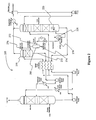
- FIG. 1 One exemplary configuration is depicted in Figure 1 in which a plant 100 in which a feed gas 102 enters the absorber 110 at feed gas pressure.
- Lean solvent 122 enters an upper portion of the absorber 110 and contacts the feed gas within the absorber to form semi-rich solvent 124, which is fed to a lower portion of the absorber 110.
- the semi-rich solvent 124 may be mixed with the semi-lean solvent 132 to form a mixed solvent (not shown).
- the semi-rich solvent 124 and the semi-lean solvent 132 may also enter the lower portion of the absorber separately.
- semi-rich solvent 124, the semi-lean solvent 132, and/or the mixed solvent may be cooled by an absorber intercooler 150.
- each of the intercoolers may cool a side draw of the absorber. Therefore, and in this context, multiple semi-rich solvent streams may be cooled. Consequently, a semi-lean cooler as shown in Figures 1 and 2 may be omitted.
- Rich solvent 106 will leave the absorber 110 at or near the bottom of the absorber, and the processed feed gas will leave the absorber 110 as lean gas 104.
- the rich solvent 106 is then split into a first and second portion (106A and 106B, respectively), wherein both portions are heated in a solvent cross exchanger 140 against the lean solvent from the first regenerator 120 and the semi-lean solvent 132 from the second regenerator 130.
- the rich solvent may be first heated in the cross exchanger (or other suitable heat source) before the rich solvent is divided into the first and second portions.
- the first regenerator 120 removes the gaseous component (e . g ., acid gas) from the solvent 106A with heat provided by the steam reboiler 128.
- First regenerator overhead 126 is further cooled in regenerator condenser 160 and separated into condensate and acid gas in accumulator 162.
- the lean solvent 122 from the first regenerator 120 is re-introduced into the absorber 110 after heat exchange in cross exchanger 140 ( supra ).
- the second regenerator 130 removes from the second portion 106B at least part of the gaseous component to generate semi-lean solvent 132 and second regenerator overhead 136, which is then combined with the first regenerator overhead 126.
- Stream 136 may also be washed in a top wash section of the first regenerator. It should be especially appreciated that the second portion of the rich solvent 106B is heated in the cross exchanger ( e . g ., against the lean solvent 122 and/or the semi-lean solvent 132) to promote regeneration of the semi-lean solvent without additional expenditure of heat energy.
- regeneration of the semi-lean solvent 232 in the second regenerator 230 may also be assisted by steam 276 that is generated within the gas treatment plant 200 (or elsewhere).
- steam 276 is derived from the steam reboiler 228 of the first regenerator 220, wherein the condensate 272 from reboiler 228 is flashed to the operating pressure of the second regenerator, and separated in the flash drum 280 into condensate flash liquid 274 and condensate flash steam 276 (with respect to the remaining configuration, the same considerations as for Figure 1 apply).
- suitable feed gases may vary considerably, and the particular composition, pressure, temperature, etc. will predominantly depend on the particular source.
- especially preferred feed gases include flue gases from reformer burner or gas turbine exhausts.
- gases other than flue gases from a combustion turbine are also contemplated, including natural gas, or various refinery gases, combustion gases, or combined gases from multiple sources, all of which may or may not be pretreated (contemplated pretreatment may include fractionation, filtration, scrubbing, and combination or dilution with other gases).
- the chemical composition may vary substantially, but suitable feed gases preferably have relatively low carbon dioxide (typically between 0.25 and 30 vol%) and relatively high oxygen content (typically between 0.25 and 20 vol%). Consequently, depending on the nature of the process gas and the physico-chemical properties of the solvent, the gaseous compound is not necessarily limited to carbon dioxide, but may also include hydrogen sulfide, nitrogen, oxygen, hydrogen, and/or helium, etc.
- the pressure of the feed gas is typically relatively low and will generally be in the range of between 1 kPa (0.1 psia) and 2.07 kPa (30 psia). However, contemplated higher pressures include pressures of between about 207 kPa (30 psia) and 1034 kPa (150 psia) and less typically between about than 1034 kPa (150 psia) and 2068 kPa (300 psia). Similarly, the temperature of contemplated feed gases may vary and will predominantly depend on the particular source and/or use of a heat recovery unit.
- contemplated absorbers include random packed-bed absorbers with a capacity of up to 30 million standard cubic feet per hour (and even more), but may include various alternative types, sizes, and capacities.
- contemplated absorbers may include structured packed-bed absorbers or trayed-type absorbers.
- Contemplated feed gas capacities include flow rates of between 1-50 million standard cubic feet per hour (MMSCF/hr), and even higher flow rates between 50-100 MMSCF/hr are also contemplated.
- flow rates of between 0.1-50 MMSCF/hr and less are also deemed suitable.
- the absorber operates at a pressure that is substantially identical (+/- 34 kPa 5 psi) to the pressure of the feed gas (which may be directly provided to the absorber as exhaust with or without a blower). Therefore, suitable absorber pressures will typically be in the range of between about 34 kPa (5 psia) to (25 172 kPa psia) more typically in the range of about 69 kPa (10) to 138 kPa (20 psia) and most typically in the range of about 96 kPa-117 kPa (14-17 psia). Alternatively, the absorber pressure may also exceed 138 kPa (20 psia), and suitable pressures of up to 2068 kPa (300 psia) (and even higher) are not excluded.
- first and second regenerators may vary substantially in type and volume, and the type and volume of suitable regenerators will depend at least in part on the absorber and nature of the feed gas. Therefore, it is generally contemplated that all conventional configurations are deemed suitable for use in conjunction herein so long as a first and second regenerator receive a first and second portion of a rich solvent directly or indirectly from the absorber, respectively, and so long as the overhead and the semi-lean solvent of the second regenerator are substantially exclusively produced from the second portion of the rich solvent.
- substantially exclusively produced from the second portion of the rich solvent means that the rich gaseous stream leaving the top of the first regenerator is typically not (or if so, then no more than 20 vol%) routed into the semi-lean solvent regenerator, and/or that the feed to the second regenerator comprises at least 80% of the second portion of the rich solvent.
- Optionally added stripping gas or steam is not included in this definition.
- the second regenerator may be operated as a flash drum that receives heated rich solvent and that may further receive steam to reduce the acid gas partial pressure above the solvent in the flash drum.
- the pressure in at least one of the first and second regenerator is higher than in the absorber, and it should be recognized that a particular pressure in the first and/or second regenerator will predominantly depend on the particular solvent and solvent concentration, temperature, and/or (residual) carbon dioxide loading in the solvent.
- contemplated pressure differences between at least one of the regenerators and the absorber will be at least 14kPa (2 psi), more typically at least 34kPa (5 psi), and most typically between 69-103 kPa (10-15 psi).
- the amount of steam provided to the second regenerator it should be recognized that the steam quantities may vary considerably.
- the reboiler of the first regenerator is not restricted to a steam operated reboiler, but may also be alternative reboilers, including oil-heated, or flame heated, or electrically heated reboilers.
- suitable pumps, valves, and piping will be readily available to a person of ordinary skill in the art, and that their implementation into the configurations according to the inventive subj ect matter will not require undue experimentation.
- the solvent is an aqueous amine-containing solvent (chemical solvent), and particularly preferred solvents include those comprising monoethanolamine (MEA).
- chemical solvents include SELEXOL TM (a dimethyl ether of polyethylene glycol) and methanol
- chemical solvents include organic amines and mixed amines.
- Suitable solvents are generally commercially available, or may be prepared to specification for selected purposes.
- contemplated solvents may additionally include corrosion inhibitors.
- corrosion inhibitors There are numerous corrosion inhibitors known in the art, and exemplary inhibitors are described, for example, in U.S. Pat. Nos. 6,036,888 , 4,596,849 , or 4,372,873 .
- suitable reagents that may be added or included to contemplated solvents are anti-foam agents, buffers, metal salts, etc.
- the rich solvent stream may be heated utilizing residual heat from the steam reboiler, or from heat sources other than a heat exchanger, including hot fluids, hot gases, and electricity.
- the cooling of the lean solvent stream and semi-lean solvent stream may be performed with a single, or two independent cooling devices that employ water, air, or other refrigerants as coolants. The cooling devices may thereby be energetically coupled or independent from the gas purification process.
- side coolers are preferably employed for such cooling
- various alternative configurations are also contemplated, including multiple side coolers or a single side cooler with two independent channels for the two solvent streams.
- the intercooler may be employed to cool the mixed solvent, and/or the semi-rich and/or semi-lean solvent stream.
- Contemplated coolers preferably reduce the temperature of the lean solvent stream and the semi-lean solvent stream more than 10°C, more preferably more than 25°C, and most preferably more than 50°C.
- Alternative cooling systems include coil-cooled trays, or internal heat exchangers.
- the semi-rich solvent stream need not be limited to a single semi-rich solvent stream with a particular carbon dioxide loading (e . g ., greater than 0.3), but may include multiple semi-rich solvent streams with identical or different carbon dioxide loading, so long as at least part of the semi-rich solvent stream is fed back to a lower portion of the absorber.
- appropriate semi-rich solvent streams may be drawn off the absorber at different positions that may or may not have the same vertical distance from the top of the absorber.
- the low pressure steam 270 for the reboiler may also be provided by a source other than the gas treatment plant, and especially suitable sources include heat recovery units of various plants ( infra ).
- suitable sources include heat recovery units of various plants ( infra ).
- contemplated plant configurations include those in which a recovery plant (e . g ., gas treatment plant for recovery of carbon dioxide) is heat-integrated with a power plant, wherein low-level heat is provided by the recovery plant to the power plant, while high-level heat is provided from the power plant to the recovery plant.
- a recovery plant may provide heating for boiler feed water of a power plant from recovery plant heat sources that include solvent coolers ( e .
- gas treatment plant gas processing plant
- recovery plant recovery plant
- gaseous component typically acid gas, most typically carbon dioxide
- FIG. 4A depicts a configuration in which flue gas ( e . g ., from a reformer) is directed through a heat recovery unit in which boiler feed water is converted to low pressure steam that can be used to operate the first regenerator of a plant having a configuration of Figure 1 .
- extra fuel may be used to raise the temperature in the heat recovery unit ( e . g ., via duct firing).
- Such heat integration configurations are particularly advantageous where the flue gas contains oxygen in an amount sufficient to support combustion of additional fuel (typically oxygen concentration of 4% (vol.), or more). Therefore, especially suitable flue gases include gas turbine exhausts and reformer flue gases.
- a heat recovery unit is positioned upstream of a flue gas treating unit (e . g ., desulfurization and/or carbon dioxide removal) in which duct firing is performed via injection of natural gas or other fuel to the flue gas.
- the combustion of the natural gas or other fuel with the remaining oxygen of the flue gas increases the flue gas temperature to the point that steam can be raised and sent to the reboiler of the first regenerator of Figures 1 or 2 .
- the Econamine FG Plus process was designed with split flow configuration, intercooled absorber, 35 wt% aqueous MEA as solvent, and with -9°C (15°F) minimum cross exchanger approach temperature.
- the heat recovery unit was designed with a minimum approach temperature of -9°C (15°F).
- the temperature of the flue gas in the desulfurization/DCC unit was set to 40°C (104°F.)
- the flue gas carbon dioxide concentration increases from 6.0 to 7.2%, thus increasing the MEA solvent capacity.
- the same removal can be obtained with a lower circulation rate and the increased rich loading makes stripping easier.
- the result is a reduction of reboiler duty of approximately 6.9%.
- the blower power increases, due to the pressure drop that the flue gas undergoes in the heat recovery unit (set to 10" H 2 O).
- power may be generated by production of higher pressure steam in the heat recovery unit (see Figure 4B ).
- the steam can be superheated and expanded in a turbine and the extraction steam 345 kPa ((50 psig) superheated) can be sent to the reboiler, while some power is produced to satisfy the demand of the Econamine FG Plus process.
- a third case (C) was run with the simulator to reproduce this configuration, with a steam pressure of 3103 kPa (450 psig).
- the Table below reports the results of that simulation, comparing the third case C to case B.
- the inventors generally contemplate a plant that includes an absorber that removes an acid gas from a feed gas using a lean solvent and a semi-lean solvent, thereby producing a semi-rich solvent and a rich solvent.
- Such plants will further comprise a first regenerator that receives a first portion of the rich solvent, thereby producing the lean solvent and a first regenerator overhead, and a second regenerator that receives a second portion of the rich solvent, thereby producing the semi-lean solvent and a second regenerator overhead, wherein the second regenerator overhead and the semi-lean solvent are substantially exclusively produced from the second portion of the rich solvent.
- the second portion of the rich solvent is preheated in a heat exchanger against the lean solvent from the first regenerator, and/or the second regenerator further receives steam from a component in the plant (e.g ., steam reboiler of the first regenerator; therefore, the steam may be a flashed steam condensate from the steam reboiler).
- a component in the plant e.g ., steam reboiler of the first regenerator; therefore, the steam may be a flashed steam condensate from the steam reboiler.
- the absorber (preferably further comprising an intercooler cooling the semi-lean, semi-rich, and/or a mixed solvent) will operate at a pressure that is lower than an operating pressure of the first regenerator and an operating pressure of the second regenerator.
- a suitable feed gas entering the absorber may be a flue gas at a pressure of no more than 138 kPa (20 psia) (e.g ., the acid gas in the feed gas is carbon dioxide and has a concentration of between 0.5% (vol.) and 3.5% (vol.) and wherein the feed gas further comprises oxygen at a concentration of between 5% (vol.) and 15% (vol.)).
- Contemplated plants may further be heat integrated with other plants (e . g ., ammonia gas production plants with a reformer, a power plant with a gas turbine, etc.) that may provide heat (typically high-level heart for steam reboiler) and advantageously the feed gas, while the other plant may also receive heat from contemplated plants (typically low level heat to preheat boiler feed water).
- other plants e . g ., ammonia gas production plants with a reformer, a power plant with a gas turbine, etc.
- heat typically high-level heart for steam reboiler
- contemplated plants typically low level heat to preheat boiler feed water
- contemplated plants will include an absorber that removes an acid gas from a low-pressure flue gas using a lean solvent and a semi-lean solvent, wherein the lean solvent is produced by a first regenerator operating at a first pressure, the semi-lean solvent is produced by a second regenerator operating at a second pressure, and wherein each of the first and second pressures are greater than a pressure of the low-pressure flue gas.
Landscapes
- Chemical & Material Sciences (AREA)
- Engineering & Computer Science (AREA)
- Analytical Chemistry (AREA)
- General Chemical & Material Sciences (AREA)
- Oil, Petroleum & Natural Gas (AREA)
- Chemical Kinetics & Catalysis (AREA)
- Gas Separation By Absorption (AREA)
- Industrial Gases (AREA)
- Treating Waste Gases (AREA)
- Vaporization, Distillation, Condensation, Sublimation, And Cold Traps (AREA)
- Organic Insulating Materials (AREA)
- Optical Communication System (AREA)
- Discharge Heating (AREA)
- Paper (AREA)
Claims (12)
- Eine Anlage umfassend: einen Absorber (110) der ausgestaltet ist zum Entfernen eines Sauergases von einem Zufuhrgas (102) unter Verwendung eines mageren Lösungsmittels (122) und eines halbmageren Lösungsmittels (132), um dadurch ein angereichertes Lösungsmittel (106) und ein halbangereichertes Lösungsmittel (124) zu erzeugen; einen ersten Regenerator (120) der ausgestaltet ist zum Aufnehmen eines ersten Anteils (106A) des angereicherten Lösungsmittels (106) und zum Erzeugen des mageren Lösungsmittels (122), das dem Absorber (110) zugeleitet ist, und eines ersten Regeneratorkopfproduktes (126); einen zweiten Regenerator (130) der ausgestaltet ist zum Aufnehmen eines zweiten Anteils (106B) des angereicherten Lösungsmittels (106) und zum Erzeugen des halbmageren Lösungsmittels (132), das dem Absorber (110) zugeleitet ist, und eines zweiten Regeneratorkopfproduktes (136);
dadurch gekennzeichnet, dass ein Wärmetauscher (140) ausgestaltet ist zum Vorheizen des zweiten Anteils (106B) des angereicherten Lösungsmittels (106) gegenüber dem mageren Lösungsmittels (122) des ersten Regenerators (120); und dass der zweite Regenerator (130) ausgestaltet ist zum exklusiven Produzieren des zweiten Regeneratorkopfproduktes (136) und des halbmageren Lösungsmittels (132) aus dem zweiten Anteil (106B) des angereicherten Lösungsmittels (106). - Anlage gemäss Anspruch 1, wobei der zweite Regenerator (130) zudem ausgestaltet ist zum Aufnehmen eines Stroms (276) von einer Komponente in der Anlage.
- Anlage gemäss Anspruch 2, wobei die Komponente ein Dampfwiedererwärmer (128) des ersten Regenerators (120) ist, und wobei der Dampf ein druckentspannter Kondensatdampf des Dampfwiedererwärmers (128) ist.
- Anlage gemäss Anspruch 1, wobei der Absorber (110) ausgestaltet ist zum Betrieb auf einem Druck der tiefer ist als ein Betriebsdruck des ersten Regenerators (120) und als ein Betriebsdruck des zweiten Regenerators (130).
- Anlage gemäss Anspruch 4, wobei das Zufuhrgas (102) Abgas umfasst, mit einem Druck von nicht mehr als 207 kPa (2.04 atm (Standard) (30 psia)).
- Anlage gemäss Anspruch 5, wobei das Sauergas im Zufuhrgas (102) Kohlendioxid ist und eine Konzentration von zwischen 0.25% (vol.) und 30% (vol.) aufweist, und wobei das Zufuhrgas (102) zudem Sauerstoff umfasst, mit einer Konzentration zwischen 0.25% (vol.) und 20% (vol.).
- Anlage gemäss Anspruch 1, wobei der Absorber (110) mit einem Zwischenkühler (150) verbunden ist, der zumindest einen Teil des halbangereicherten Lösungsmittels (124) erhält und kühlt, um ein gekühltes, halbangereichertes Lösungsmittel zu bilden, das wieder in den Absorber (110) eingeführt ist.
- Anlage gemäss Anspruch 7, weiter umfassend eine Vorrichtung die ausgestaltet ist um zumindest einen Teil des halbmageren Lösungsmittels (132) mit dem halbangereicherten Lösungsmittel (124) zu mischen, um ein gemischtes Lösungsmittel zu bilden, und wobei der Zwischenkühler (150) ausgestaltet ist zum Kühle des gemischten Lösungsmittels um ein gekühltes gemischtes Lösungsmittel zu bilden.
- Anlage gemäss Anspruch 1, wobei der Absorber (110) mit einem Zwischenkühler (150) verbunden ist, der ausgestaltet ist zum Empfangen und Kühlen von zumindest einem Teil des halbmageren Lösungsmittels (132) um ein gekühltes halbmageres Lösungsmittel auszubilden.
- Anlage gemäss Anspruch 1, optional umfassend einen Zwischenkühler (150) der optional mit dem Absorber (110) verbunden ist, wobei ein Kraftwerk oder eine Reformierungsanlage optional mit der Anlage verbunden ist, und wobei das Kraftwerk oder die Reformierungsanlage zur Verfügung stellt: (a) Energie für einen Wiedererwärmer des ersten Regenerators (120), (b) ein Zufuhrgas das in den Absorber (110) geführt ist, und (c) wobei die Energie optional durch eine Wärmerückgewinnungseinheit erzeugt ist, welche eine Rohrheizung verwendet.
- Anlage gemäss Anspruch 10, zudem umfassend zumindest eine der folgenden Einheiten; einen Magerlösungsmittelkühler, einen Halbmagerlösungsmittelkühler, und einen Regeneratorkondensator, und wobei Wärme dem Kraftwerk zugeführt ist, durch zumindest eine der folgenden Einheiten; den Magerlösungsmittelkühler, den Halbmagerlösungsmittelkühler, den Regeneratorkondensator, und den Zwischenkühler.
- Anlage gemäss Anspruch 1, optional umfassend einen Zwischenkühler der optional an den Absorber verbunden ist, und zudem umfassend zumindest eine der folgenden Einheiten: einen Magerlösungsmittelkühler, einen Halbmagerlösungsmittelkühler, und einen Regeneratorkondensator, wobei ein Kraftwerk optional mit der Anlage verbunden ist, und wobei Wärme dem Kraftwerk zugeführt ist, durch zumindest eine der folgenden Einheiten; den Magerlösungsmittelkühler, den Halbmagerlösungsmittelkühler, den Regeneratorkondensator, und den Zwischenkühler.
Applications Claiming Priority (5)
| Application Number | Priority Date | Filing Date | Title |
|---|---|---|---|
| US39359502P | 2002-07-03 | 2002-07-03 | |
| US393595P | 2002-07-03 | ||
| US46771903P | 2003-05-02 | 2003-05-02 | |
| US467719P | 2003-05-02 | ||
| PCT/US2003/021194 WO2004005818A2 (en) | 2002-07-03 | 2003-07-03 | Improved split flow process and apparatus |
Publications (3)
| Publication Number | Publication Date |
|---|---|
| EP1551532A2 EP1551532A2 (de) | 2005-07-13 |
| EP1551532A4 EP1551532A4 (de) | 2007-02-21 |
| EP1551532B1 true EP1551532B1 (de) | 2008-11-19 |
Family
ID=30118380
Family Applications (1)
| Application Number | Title | Priority Date | Filing Date |
|---|---|---|---|
| EP03763280A Expired - Lifetime EP1551532B1 (de) | 2002-07-03 | 2003-07-03 | Verbesserte vorrichtung zum teilen von strömen |
Country Status (11)
| Country | Link |
|---|---|
| US (1) | US7377967B2 (de) |
| EP (1) | EP1551532B1 (de) |
| JP (1) | JP4105689B2 (de) |
| AT (1) | ATE414564T1 (de) |
| AU (1) | AU2003251783B2 (de) |
| CA (1) | CA2491163C (de) |
| DE (1) | DE60324822D1 (de) |
| ES (1) | ES2316817T3 (de) |
| NO (1) | NO329103B1 (de) |
| WO (1) | WO2004005818A2 (de) |
| ZA (1) | ZA200500096B (de) |
Cited By (1)
| Publication number | Priority date | Publication date | Assignee | Title |
|---|---|---|---|---|
| WO2020106396A1 (en) * | 2018-11-19 | 2020-05-28 | Exxonmobil Upstream Research Company | Co-current gas absortion method and system with an enhanced absorbent |
Families Citing this family (100)
| Publication number | Priority date | Publication date | Assignee | Title |
|---|---|---|---|---|
| JP4690659B2 (ja) | 2004-03-15 | 2011-06-01 | 三菱重工業株式会社 | Co2回収装置 |
| CA2574633C (en) | 2004-08-06 | 2010-08-10 | Eig, Inc. | Ultra cleaning of combustion gas including the removal of co2 |
| JP4745682B2 (ja) * | 2005-02-23 | 2011-08-10 | 関西電力株式会社 | Co2回収装置および方法 |
| WO2006118795A1 (en) * | 2005-04-29 | 2006-11-09 | Fluor Technologies Corporation | Configurations and methods for acid gas absorption and solvent regeneration |
| JP5021917B2 (ja) * | 2005-09-01 | 2012-09-12 | 三菱重工業株式会社 | Co2回収装置及び方法 |
| CA2632425A1 (en) * | 2005-12-19 | 2007-07-05 | Fluor Technologies Corporation | Integrated compressor/stripper configurations and methods |
| WO2007104800A1 (de) * | 2006-03-16 | 2007-09-20 | Basf Se | Verfahren zum inkontaktbringen zweier phasen, deren kontakt von wärmeentwicklung begleitet ist |
| US20070221065A1 (en) * | 2006-03-23 | 2007-09-27 | Adisorn Aroonwilas | Heat recovery gas absorption process |
| EP2107930B1 (de) * | 2007-01-25 | 2012-04-18 | Shell Internationale Research Maatschappij B.V. | Verfahren zur verringerung der kohlendioxidemission in einem kraftwerk |
| WO2008090167A1 (en) * | 2007-01-25 | 2008-07-31 | Shell Internationale Research Maatschappij B.V. | Process for producing a pressurised co2 stream in a power plant integrated with a co2 capture unit |
| US7981196B2 (en) * | 2007-06-04 | 2011-07-19 | Posco | Apparatus and method for recovering carbon dioxide from flue gas using ammonia water |
| US8182577B2 (en) | 2007-10-22 | 2012-05-22 | Alstom Technology Ltd | Multi-stage CO2 removal system and method for processing a flue gas stream |
| US7862788B2 (en) | 2007-12-05 | 2011-01-04 | Alstom Technology Ltd | Promoter enhanced chilled ammonia based system and method for removal of CO2 from flue gas stream |
| US8192530B2 (en) * | 2007-12-13 | 2012-06-05 | Alstom Technology Ltd | System and method for regeneration of an absorbent solution |
| US20090151564A1 (en) * | 2007-12-13 | 2009-06-18 | Alstom Technology Ltd. | System and method for removal of an acidic component from a process stream |
| US20090151318A1 (en) * | 2007-12-13 | 2009-06-18 | Alstom Technology Ltd | System and method for regenerating an absorbent solution |
| BRPI0907784A8 (pt) * | 2008-02-18 | 2015-09-29 | Fluor Tech Corp | configuração de regenerador e métodos com reduzida demanda de vapor |
| WO2009112518A1 (en) * | 2008-03-13 | 2009-09-17 | Shell Internationale Research Maatschappij B.V. | Process for removal of carbon dioxide from a gas |
| EP2105187A1 (de) * | 2008-03-27 | 2009-09-30 | Siemens Aktiengesellschaft | Verfahren und Vorrichtung zum Abtrennen von Kohlendioxid aus einem Abgas einer fossilbefeuerten Kraftwerksanlage |
| EP2105190A1 (de) * | 2008-03-27 | 2009-09-30 | Siemens Aktiengesellschaft | Verfahren und Vorrichtung zum Abtrennen von Kohlendioxid aus einem Abgas einer fossilbefeuerten Kraftwerksanlage |
| EP2105188A1 (de) * | 2008-03-27 | 2009-09-30 | Siemens Aktiengesellschaft | Verfahren und Vorrichtung zum Abtrennen von Kohlendioxid aus einem Abgas einer fossilbefeuerten Kraftwerksanlage |
| EP2105191A1 (de) * | 2008-03-27 | 2009-09-30 | Siemens Aktiengesellschaft | Verfahren und Vorrichtung zum Abtrennen von Kohlendioxid aus einem Abgas einer fossilbefeuerten Kraftwerksanlage |
| US8080089B1 (en) * | 2008-04-14 | 2011-12-20 | Bechtel Power Corporation | Method and apparatus for efficient gas treating system |
| BRPI0910840B1 (pt) * | 2008-04-29 | 2018-05-08 | Celanese International Corporation | aparelho para produção de ácido acético, método de operação de uma torre absorvedora em uma unidade de carbonilação e método aperfeiçoado para operação de um aparelho para fabricação de ácido acético |
| EP2293862A1 (de) | 2008-06-19 | 2011-03-16 | Shell Internationale Research Maatschappij B.V. | Verfahren zur entfernung von kohlendioxid aus einem gas |
| EP2145667A1 (de) * | 2008-07-17 | 2010-01-20 | Siemens Aktiengesellschaft | Verfahren und Vorrichtung zum Abtrennen von Kohlendioxid aus einem Abgas einer fossilbefeuerten Kraftwerksanlage |
| FR2936165B1 (fr) * | 2008-09-23 | 2011-04-08 | Inst Francais Du Petrole | Procede de desacidification d'un gaz par solution absorbante avec controle de la demixtion |
| US7846240B2 (en) | 2008-10-02 | 2010-12-07 | Alstom Technology Ltd | Chilled ammonia based CO2 capture system with water wash system |
| US8404027B2 (en) | 2008-11-04 | 2013-03-26 | Alstom Technology Ltd | Reabsorber for ammonia stripper offgas |
| US9440182B2 (en) | 2008-12-24 | 2016-09-13 | General Electric Company | Liquid carbon dioxide absorbents, methods of using the same, and related systems |
| US20100154431A1 (en) * | 2008-12-24 | 2010-06-24 | General Electric Company | Liquid carbon dioxide absorbent and methods of using the same |
| US7785399B2 (en) * | 2009-01-16 | 2010-08-31 | Uop Llc | Heat integration for hot solvent stripping loop in an acid gas removal process |
| US8123842B2 (en) * | 2009-01-16 | 2012-02-28 | Uop Llc | Direct contact cooling in an acid gas removal process |
| BRPI0924205B1 (pt) * | 2009-01-28 | 2019-05-07 | Siemens Aktiengesellschaft | Método para a separação de dióxido de carbono de um gás de exaustão de uma usina de força alimentada a energia fóssil. |
| DE102009009753B4 (de) * | 2009-02-20 | 2014-01-30 | Mt-Biomethan Gmbh | Verfahren zur chemisorptiven Reinigung von Bio- oder Klärgas |
| US8292989B2 (en) | 2009-10-30 | 2012-10-23 | Alstom Technology Ltd | Gas stream processing |
| US8845789B2 (en) * | 2009-03-31 | 2014-09-30 | Alstom Technology Ltd | Process for CO2 capture with improved stripper performance |
| JP5383338B2 (ja) | 2009-06-17 | 2014-01-08 | 三菱重工業株式会社 | Co2回収装置及びco2回収方法 |
| US8790605B2 (en) | 2009-09-15 | 2014-07-29 | Alstom Technology Ltd | Method for removal of carbon dioxide from a process gas |
| US8784761B2 (en) | 2009-11-20 | 2014-07-22 | Alstom Technology Ltd | Single absorber vessel to capture CO2 |
| US8309047B2 (en) | 2009-09-15 | 2012-11-13 | Alstom Technology Ltd | Method and system for removal of carbon dioxide from a process gas |
| US8518156B2 (en) * | 2009-09-21 | 2013-08-27 | Alstom Technology Ltd | Method and system for regenerating a solution used in a wash vessel |
| EP2322265A1 (de) | 2009-11-12 | 2011-05-18 | Alstom Technology Ltd | Rauchgasbehandlungssystem |
| US8460436B2 (en) | 2009-11-24 | 2013-06-11 | Alstom Technology Ltd | Advanced intercooling and recycling in CO2 absorption |
| DE102009056660B4 (de) * | 2009-12-02 | 2014-09-25 | Mt-Biomethan Gmbh | Verfahren und Anlage zur chemisorptiven Abtrennung von Kohlendioxid aus Bio- oder Klärgas mittels einer aminhaltigen Waschlösung und Regeneration der beladenen Waschlösung |
| US8293200B2 (en) | 2009-12-17 | 2012-10-23 | Alstom Technology Ltd | Desulfurization of, and removal of carbon dioxide from, gas mixtures |
| FR2954178B1 (fr) * | 2009-12-21 | 2014-02-21 | Air Liquide | Procede d'epuration d'un gaz contenant du dioxyde de carbone |
| JP5737844B2 (ja) * | 2010-02-08 | 2015-06-17 | 三菱重工業株式会社 | Co2回収装置の熱回収設備および熱回収方法 |
| CA2787146C (en) * | 2010-02-17 | 2016-05-17 | Fluor Technologies Corporation | Configurations and methods of high pressure acid gas removal in the production of ultra-low sulfur gas |
| JP5665022B2 (ja) * | 2010-03-31 | 2015-02-04 | 新日鉄住金エンジニアリング株式会社 | 二酸化炭素ガス回収装置 |
| DE102010003676A1 (de) * | 2010-04-07 | 2011-10-13 | Siemens Aktiengesellschaft | Abscheidevorrichtung für CO2 und Kraftwerk |
| EP2383522B1 (de) | 2010-04-28 | 2016-11-02 | General Electric Technology GmbH | Thermische Integration der Kohlendioxiderfassung und Komprimiervorrichtung mit Dampf- oder kombinierter Zyklusanlage |
| CN102971508B (zh) | 2010-07-02 | 2016-06-01 | 埃克森美孚上游研究公司 | Co2分离系统和分离co2的方法 |
| US8728209B2 (en) | 2010-09-13 | 2014-05-20 | Alstom Technology Ltd | Method and system for reducing energy requirements of a CO2 capture system |
| US8623307B2 (en) | 2010-09-14 | 2014-01-07 | Alstom Technology Ltd. | Process gas treatment system |
| US20120064610A1 (en) * | 2010-09-15 | 2012-03-15 | Alstom Technology Ltd | Solvent and method for co2 capture from flue gas |
| WO2012038868A1 (en) * | 2010-09-20 | 2012-03-29 | Prateek Bumb | Solvent composition for carbon dioxide recovery |
| JP5697411B2 (ja) | 2010-11-17 | 2015-04-08 | 株式会社東芝 | 二酸化炭素回収装置および二酸化炭素回収方法 |
| JP5591083B2 (ja) * | 2010-12-01 | 2014-09-17 | 三菱重工業株式会社 | Co2回収システム |
| JP5737916B2 (ja) * | 2010-12-01 | 2015-06-17 | 三菱重工業株式会社 | Co2回収システム |
| JP5174194B2 (ja) * | 2011-01-04 | 2013-04-03 | 三菱重工業株式会社 | Co2回収装置及び方法 |
| US8329128B2 (en) | 2011-02-01 | 2012-12-11 | Alstom Technology Ltd | Gas treatment process and system |
| US9901860B2 (en) | 2011-02-02 | 2018-02-27 | General Electric Technology Gmbh | Apparatus for removing an acid gas from a gas stream |
| JP2014505593A (ja) | 2011-02-02 | 2014-03-06 | アルストム テクノロジー リミテッド | 再生エネルギーの低減方法 |
| US9028784B2 (en) | 2011-02-15 | 2015-05-12 | Alstom Technology Ltd | Process and system for cleaning a gas stream |
| US9133407B2 (en) | 2011-02-25 | 2015-09-15 | Alstom Technology Ltd | Systems and processes for removing volatile degradation products produced in gas purification |
| US9427695B2 (en) * | 2011-04-06 | 2016-08-30 | Alstom Technology Ltd | Carbon dioxide capture system |
| US8329125B2 (en) | 2011-04-27 | 2012-12-11 | Primex Process Specialists, Inc. | Flue gas recirculation system |
| US9259680B2 (en) | 2011-09-06 | 2016-02-16 | Frank Bela | Claus hydrocarbon destruction via staged solvent regeneration |
| US8864878B2 (en) | 2011-09-23 | 2014-10-21 | Alstom Technology Ltd | Heat integration of a cement manufacturing plant with an absorption based carbon dioxide capture process |
| US8911538B2 (en) | 2011-12-22 | 2014-12-16 | Alstom Technology Ltd | Method and system for treating an effluent stream generated by a carbon capture system |
| EP2609988A1 (de) * | 2011-12-29 | 2013-07-03 | Dreyer & Bosse Kraftwerke GmbH | Niedertemperaturverfahren zur Desorption beladener aminhaltiger Waschflüssigkeiten aus Gaswaschprozessen und Vorrichtung |
| US9162177B2 (en) | 2012-01-25 | 2015-10-20 | Alstom Technology Ltd | Ammonia capturing by CO2 product liquid in water wash liquid |
| US9021810B2 (en) * | 2012-01-27 | 2015-05-05 | The University Of Kentucky Research Foundation | Fossil-fuel-fired power plant |
| DE102013200755A1 (de) * | 2012-02-22 | 2013-08-22 | Siemens Aktiengesellschaft | Kohledioxidabscheidevorrichtung zur Abscheidung von Kohledioxid aus einem Verbrennungsabgas |
| US9028654B2 (en) | 2012-02-29 | 2015-05-12 | Alstom Technology Ltd | Method of treatment of amine waste water and a system for accomplishing the same |
| US8864879B2 (en) | 2012-03-30 | 2014-10-21 | Jalal Askander | System for recovery of ammonia from lean solution in a chilled ammonia process utilizing residual flue gas |
| KR101951047B1 (ko) * | 2012-09-20 | 2019-02-21 | 한국전력공사 | 화학적 흡수제를 이용한 이산화탄소의 흡수 및 탈거 장치 |
| GB201218949D0 (en) | 2012-10-22 | 2012-12-05 | Bp Alternative Energy Internat Ltd | Separatiion of components from a gas mixture |
| WO2014066539A1 (en) | 2012-10-24 | 2014-05-01 | Fluor Technologies Corporation | Integration methods of gas processing plant and nitrogen rejection unit for high nitrogen feed gases |
| US9101912B2 (en) | 2012-11-05 | 2015-08-11 | Alstom Technology Ltd | Method for regeneration of solid amine CO2 capture beds |
| US9447996B2 (en) | 2013-01-15 | 2016-09-20 | General Electric Technology Gmbh | Carbon dioxide removal system using absorption refrigeration |
| JP2015024398A (ja) | 2013-07-29 | 2015-02-05 | 株式会社東芝 | 二酸化炭素分離回収システム及びその運転方法 |
| US10000713B2 (en) | 2013-12-12 | 2018-06-19 | Fluor Technologies Corporation | Configurations and methods of flexible CO2 removal |
| US8986640B1 (en) | 2014-01-07 | 2015-03-24 | Alstom Technology Ltd | System and method for recovering ammonia from a chilled ammonia process |
| WO2015188166A2 (en) * | 2014-06-06 | 2015-12-10 | Virginia Tech Intellectual Properties, Inc. | Energy-efficient extraction of acid gas from flue gases |
| CN104389680B (zh) * | 2014-11-12 | 2016-01-20 | 山东大学 | 基于sofc/gt混合发电系统和膜分离的低碳排放功冷联供系统 |
| EP3031510B1 (de) * | 2014-12-11 | 2017-05-31 | Union Engineering A/S | Verfahren zur Gewinnung von Kohlendioxid aus einem Absorbtionsmittel mit reduzierter Zufuhr von Strippdampf |
| EP3250311A4 (de) * | 2015-01-28 | 2019-02-13 | Fluor Technologies Corporation | Verfahren und system zur verbesserung der energieeffizienz von kohlendioxidabscheidung |
| AU2016236357B2 (en) * | 2015-03-20 | 2019-03-28 | Shell Internationale Research Maatschappij B.V. | Process for producing a purified gas stream from natural gas wells |
| US10378763B2 (en) | 2015-12-03 | 2019-08-13 | General Electric Company | Method and apparatus to facilitate heating feedwater in a power generation system |
| EP3192984B1 (de) * | 2016-01-13 | 2020-06-17 | General Electric Technology GmbH | Verfahren zum betrieb einer dampfkraftanlage und dampfkraftanlage zur durchführung des verfahrens |
| US10376829B2 (en) | 2017-06-13 | 2019-08-13 | Fluor Technologies Corporation | Methods and systems for improving the energy efficiency of carbon dioxide capture |
| US10710020B2 (en) | 2017-06-30 | 2020-07-14 | Uop Llc | Processes for gas separation by solvent or absorbent |
| EP3441122A1 (de) * | 2017-08-07 | 2019-02-13 | L'air Liquide, Société Anonyme Pour L'Étude Et L'exploitation Des Procédés Georges Claude | Kolonne zum strippen und reabsorbieren |
| US11090604B2 (en) | 2018-11-19 | 2021-08-17 | Exxonmobil Upstream Research Company | Enhanced acid gas removal within a gas processing system |
| WO2022008876A1 (en) * | 2020-07-10 | 2022-01-13 | Carbon Clean Solutions Limited | A method and system for the removal of carbon dioxide from solvents using low-grade heat |
| JP7407685B2 (ja) * | 2020-10-05 | 2024-01-04 | 株式会社神戸製鋼所 | ガス処理装置 |
| US12318727B2 (en) | 2021-12-20 | 2025-06-03 | Ge Infrastructure Technology Llc | System and method for controlling a temperature in an absorber |
| US20240416273A1 (en) * | 2023-06-13 | 2024-12-19 | Mitsubishi Heavy Industries, Ltd. | Carbon dioxide recovery system |
Citations (2)
| Publication number | Priority date | Publication date | Assignee | Title |
|---|---|---|---|---|
| EP0588175A2 (de) * | 1992-09-16 | 1994-03-23 | The Kansai Electric Power Co., Inc. | Verfahren zur Beseitigung von Kohlendioxyd aus Abgasen |
| EP1201290A1 (de) * | 1999-07-19 | 2002-05-02 | Ebara Corporation | Verfahren und vorrichtung zur reinigung von saurem gas |
Family Cites Families (12)
| Publication number | Priority date | Publication date | Assignee | Title |
|---|---|---|---|---|
| US1971798A (en) * | 1932-01-30 | 1934-08-28 | Koppers Co Delaware | Purification and separation of gaseous mixtures |
| US2437288A (en) * | 1943-12-28 | 1948-03-09 | Ray B Anderson | Separation of gaseous mixtures |
| US3851041A (en) * | 1966-02-01 | 1974-11-26 | A Eickmeyer | Method for removing acid gases from gaseous mixtures |
| NL7402037A (de) * | 1973-02-16 | 1974-08-20 | ||
| IT1046519B (it) * | 1974-11-08 | 1980-07-31 | Vetrocoke Cokapuania Spa | Procedimento migliorato per la eliminazione e il ricupero di gas acidi co 2 e o h2s da miscele gassose che li contengono |
| IT1064936B (it) * | 1976-07-13 | 1985-02-25 | Giammarco Giuseppe | Procedimento per l assorbimento di co 2..h2s e simili impurezze e rigenerazione della soluzione con ritorno di calore in colonna di rigenerazione mediante una corrente di gas inerti |
| US4198378A (en) * | 1976-11-12 | 1980-04-15 | Giuseppe Giammarco | Process for removing CO2, H2 S and other gaseous impurities from gaseous mixtures |
| IT1156991B (it) * | 1978-04-27 | 1987-02-04 | Giuseppe Giammarco | Procedimento migliorato per la purificazione di liquidi e o per la rigenerazione di soluzioni assorbenti |
| GB9702742D0 (en) * | 1997-02-11 | 1997-04-02 | Ici Plc | Gas absorption |
| ATE425806T1 (de) * | 1998-11-23 | 2009-04-15 | Fluor Corp | Vorrichtung zur aufteilung einer strímung |
| US6800120B1 (en) * | 1998-11-23 | 2004-10-05 | Fluor Corporation | Split-flow process and apparatus |
| US7056482B2 (en) * | 2003-06-12 | 2006-06-06 | Cansolv Technologies Inc. | Method for recovery of CO2 from gas streams |
-
2003
- 2003-07-03 US US10/519,258 patent/US7377967B2/en not_active Expired - Lifetime
- 2003-07-03 EP EP03763280A patent/EP1551532B1/de not_active Expired - Lifetime
- 2003-07-03 AU AU2003251783A patent/AU2003251783B2/en not_active Ceased
- 2003-07-03 JP JP2004519955A patent/JP4105689B2/ja not_active Expired - Fee Related
- 2003-07-03 ES ES03763280T patent/ES2316817T3/es not_active Expired - Lifetime
- 2003-07-03 DE DE60324822T patent/DE60324822D1/de not_active Expired - Lifetime
- 2003-07-03 WO PCT/US2003/021194 patent/WO2004005818A2/en not_active Ceased
- 2003-07-03 AT AT03763280T patent/ATE414564T1/de active
- 2003-07-03 CA CA002491163A patent/CA2491163C/en not_active Expired - Fee Related
-
2005
- 2005-01-05 ZA ZA2005/00096A patent/ZA200500096B/en unknown
- 2005-01-06 NO NO20050089A patent/NO329103B1/no not_active IP Right Cessation
Patent Citations (2)
| Publication number | Priority date | Publication date | Assignee | Title |
|---|---|---|---|---|
| EP0588175A2 (de) * | 1992-09-16 | 1994-03-23 | The Kansai Electric Power Co., Inc. | Verfahren zur Beseitigung von Kohlendioxyd aus Abgasen |
| EP1201290A1 (de) * | 1999-07-19 | 2002-05-02 | Ebara Corporation | Verfahren und vorrichtung zur reinigung von saurem gas |
Cited By (1)
| Publication number | Priority date | Publication date | Assignee | Title |
|---|---|---|---|---|
| WO2020106396A1 (en) * | 2018-11-19 | 2020-05-28 | Exxonmobil Upstream Research Company | Co-current gas absortion method and system with an enhanced absorbent |
Also Published As
| Publication number | Publication date |
|---|---|
| EP1551532A4 (de) | 2007-02-21 |
| WO2004005818A3 (en) | 2004-03-25 |
| CA2491163A1 (en) | 2004-01-15 |
| JP2005532157A (ja) | 2005-10-27 |
| ES2316817T3 (es) | 2009-04-16 |
| NO329103B1 (no) | 2010-08-23 |
| DE60324822D1 (de) | 2009-01-02 |
| WO2004005818A2 (en) | 2004-01-15 |
| EP1551532A2 (de) | 2005-07-13 |
| ZA200500096B (en) | 2005-12-28 |
| WO2004005818B1 (en) | 2004-06-24 |
| US7377967B2 (en) | 2008-05-27 |
| AU2003251783B2 (en) | 2007-08-09 |
| NO20050089L (no) | 2005-02-02 |
| US20060032377A1 (en) | 2006-02-16 |
| JP4105689B2 (ja) | 2008-06-25 |
| AU2003251783A1 (en) | 2004-01-23 |
| ATE414564T1 (de) | 2008-12-15 |
| CA2491163C (en) | 2009-06-09 |
Similar Documents
| Publication | Publication Date | Title |
|---|---|---|
| US7377967B2 (en) | Split flow process and apparatus | |
| US7901487B2 (en) | Regeneration of an aqueous solution from an acid gas absorption process by multistage flashing and stripping | |
| US6645446B1 (en) | Split-flow process and apparatus | |
| US6800120B1 (en) | Split-flow process and apparatus | |
| EP2164608B1 (de) | Verfahren zur gewinnung einer gasförmigen komponente aus einem gasstrom | |
| US6655150B1 (en) | Method for removing and recovering CO2 from exhaust gas | |
| EP2167891B1 (de) | Vorrichtung und verfahren zur trennung einer gasförmigen mischung | |
| US7901488B2 (en) | Regeneration of an aqueous solution from an acid gas absorption process by matrix stripping | |
| US20170333831A1 (en) | Process for separating a product gas from a gaseous mixture utilizing a gas pressurized separation column and a system to perform the same | |
| KR102233842B1 (ko) | 공정열을 활용한 이산화탄소 포집 시스템 및 그를 이용한 이산화탄소 포집 방법 | |
| WO2013081460A1 (en) | Method for depleting an exhaust gas stream in gaseous acid | |
| KR20260009368A (ko) | 탈산된 유체 스트림을 생성하는 방법, 유체 스트림을 탈산하기 위한 장치 및 유체 스트림을 탈산하기 위한 히트 펌프의 용도 | |
| US9028593B2 (en) | Method and absorbent compositions for recovering a gaseous component from a gas stream | |
| US20250367593A1 (en) | Combined Carbon Dioxide Removal Plant Process |
Legal Events
| Date | Code | Title | Description |
|---|---|---|---|
| PUAI | Public reference made under article 153(3) epc to a published international application that has entered the european phase |
Free format text: ORIGINAL CODE: 0009012 |
|
| 17P | Request for examination filed |
Effective date: 20050112 |
|
| AK | Designated contracting states |
Kind code of ref document: A2 Designated state(s): AT BE BG CH CY CZ DE DK EE ES FI FR GB GR HU IE IT LI LU MC NL PT RO SE SI SK TR |
|
| AX | Request for extension of the european patent |
Extension state: AL LT LV MK |
|
| DAX | Request for extension of the european patent (deleted) | ||
| RAP1 | Party data changed (applicant data changed or rights of an application transferred) |
Owner name: FLUOR CORPORATION |
|
| A4 | Supplementary search report drawn up and despatched |
Effective date: 20070122 |
|
| 17Q | First examination report despatched |
Effective date: 20070816 |
|
| GRAP | Despatch of communication of intention to grant a patent |
Free format text: ORIGINAL CODE: EPIDOSNIGR1 |
|
| RTI1 | Title (correction) |
Free format text: IMPROVED SPLIT FLOW APPARATUS |
|
| GRAS | Grant fee paid |
Free format text: ORIGINAL CODE: EPIDOSNIGR3 |
|
| GRAA | (expected) grant |
Free format text: ORIGINAL CODE: 0009210 |
|
| AK | Designated contracting states |
Kind code of ref document: B1 Designated state(s): AT BE BG CH CY CZ DE DK EE ES FI FR GB GR HU IE IT LI LU MC NL PT RO SE SI SK TR |
|
| REG | Reference to a national code |
Ref country code: GB Ref legal event code: FG4D |
|
| REG | Reference to a national code |
Ref country code: CH Ref legal event code: EP |
|
| REG | Reference to a national code |
Ref country code: IE Ref legal event code: FG4D |
|
| REF | Corresponds to: |
Ref document number: 60324822 Country of ref document: DE Date of ref document: 20090102 Kind code of ref document: P |
|
| REG | Reference to a national code |
Ref country code: ES Ref legal event code: FG2A Ref document number: 2316817 Country of ref document: ES Kind code of ref document: T3 |
|
| PG25 | Lapsed in a contracting state [announced via postgrant information from national office to epo] |
Ref country code: FI Free format text: LAPSE BECAUSE OF FAILURE TO SUBMIT A TRANSLATION OF THE DESCRIPTION OR TO PAY THE FEE WITHIN THE PRESCRIBED TIME-LIMIT Effective date: 20081119 Ref country code: SI Free format text: LAPSE BECAUSE OF FAILURE TO SUBMIT A TRANSLATION OF THE DESCRIPTION OR TO PAY THE FEE WITHIN THE PRESCRIBED TIME-LIMIT Effective date: 20081119 |
|
| PG25 | Lapsed in a contracting state [announced via postgrant information from national office to epo] |
Ref country code: DK Free format text: LAPSE BECAUSE OF FAILURE TO SUBMIT A TRANSLATION OF THE DESCRIPTION OR TO PAY THE FEE WITHIN THE PRESCRIBED TIME-LIMIT Effective date: 20081119 Ref country code: BG Free format text: LAPSE BECAUSE OF FAILURE TO SUBMIT A TRANSLATION OF THE DESCRIPTION OR TO PAY THE FEE WITHIN THE PRESCRIBED TIME-LIMIT Effective date: 20090219 Ref country code: RO Free format text: LAPSE BECAUSE OF FAILURE TO SUBMIT A TRANSLATION OF THE DESCRIPTION OR TO PAY THE FEE WITHIN THE PRESCRIBED TIME-LIMIT Effective date: 20081119 Ref country code: EE Free format text: LAPSE BECAUSE OF FAILURE TO SUBMIT A TRANSLATION OF THE DESCRIPTION OR TO PAY THE FEE WITHIN THE PRESCRIBED TIME-LIMIT Effective date: 20081119 |
|
| PG25 | Lapsed in a contracting state [announced via postgrant information from national office to epo] |
Ref country code: SE Free format text: LAPSE BECAUSE OF FAILURE TO SUBMIT A TRANSLATION OF THE DESCRIPTION OR TO PAY THE FEE WITHIN THE PRESCRIBED TIME-LIMIT Effective date: 20090219 Ref country code: PT Free format text: LAPSE BECAUSE OF FAILURE TO SUBMIT A TRANSLATION OF THE DESCRIPTION OR TO PAY THE FEE WITHIN THE PRESCRIBED TIME-LIMIT Effective date: 20090420 |
|
| PLBE | No opposition filed within time limit |
Free format text: ORIGINAL CODE: 0009261 |
|
| STAA | Information on the status of an ep patent application or granted ep patent |
Free format text: STATUS: NO OPPOSITION FILED WITHIN TIME LIMIT |
|
| PG25 | Lapsed in a contracting state [announced via postgrant information from national office to epo] |
Ref country code: SK Free format text: LAPSE BECAUSE OF FAILURE TO SUBMIT A TRANSLATION OF THE DESCRIPTION OR TO PAY THE FEE WITHIN THE PRESCRIBED TIME-LIMIT Effective date: 20081119 |
|
| 26N | No opposition filed |
Effective date: 20090820 |
|
| PG25 | Lapsed in a contracting state [announced via postgrant information from national office to epo] |
Ref country code: MC Free format text: LAPSE BECAUSE OF NON-PAYMENT OF DUE FEES Effective date: 20090731 |
|
| REG | Reference to a national code |
Ref country code: CH Ref legal event code: PL |
|
| PG25 | Lapsed in a contracting state [announced via postgrant information from national office to epo] |
Ref country code: CH Free format text: LAPSE BECAUSE OF NON-PAYMENT OF DUE FEES Effective date: 20090731 Ref country code: LI Free format text: LAPSE BECAUSE OF NON-PAYMENT OF DUE FEES Effective date: 20090731 |
|
| PG25 | Lapsed in a contracting state [announced via postgrant information from national office to epo] |
Ref country code: IE Free format text: LAPSE BECAUSE OF NON-PAYMENT OF DUE FEES Effective date: 20090703 |
|
| PG25 | Lapsed in a contracting state [announced via postgrant information from national office to epo] |
Ref country code: GR Free format text: LAPSE BECAUSE OF FAILURE TO SUBMIT A TRANSLATION OF THE DESCRIPTION OR TO PAY THE FEE WITHIN THE PRESCRIBED TIME-LIMIT Effective date: 20090220 |
|
| PG25 | Lapsed in a contracting state [announced via postgrant information from national office to epo] |
Ref country code: LU Free format text: LAPSE BECAUSE OF NON-PAYMENT OF DUE FEES Effective date: 20090703 |
|
| PG25 | Lapsed in a contracting state [announced via postgrant information from national office to epo] |
Ref country code: IT Free format text: LAPSE BECAUSE OF NON-PAYMENT OF DUE FEES Effective date: 20100703 |
|
| PG25 | Lapsed in a contracting state [announced via postgrant information from national office to epo] |
Ref country code: HU Free format text: LAPSE BECAUSE OF FAILURE TO SUBMIT A TRANSLATION OF THE DESCRIPTION OR TO PAY THE FEE WITHIN THE PRESCRIBED TIME-LIMIT Effective date: 20090520 |
|
| PGFP | Annual fee paid to national office [announced via postgrant information from national office to epo] |
Ref country code: CZ Payment date: 20110616 Year of fee payment: 9 |
|
| PGRI | Patent reinstated in contracting state [announced from national office to epo] |
Ref country code: IT Effective date: 20110616 |
|
| PG25 | Lapsed in a contracting state [announced via postgrant information from national office to epo] |
Ref country code: TR Free format text: LAPSE BECAUSE OF FAILURE TO SUBMIT A TRANSLATION OF THE DESCRIPTION OR TO PAY THE FEE WITHIN THE PRESCRIBED TIME-LIMIT Effective date: 20081119 |
|
| PG25 | Lapsed in a contracting state [announced via postgrant information from national office to epo] |
Ref country code: CY Free format text: LAPSE BECAUSE OF FAILURE TO SUBMIT A TRANSLATION OF THE DESCRIPTION OR TO PAY THE FEE WITHIN THE PRESCRIBED TIME-LIMIT Effective date: 20081119 |
|
| PGFP | Annual fee paid to national office [announced via postgrant information from national office to epo] |
Ref country code: AT Payment date: 20120620 Year of fee payment: 10 |
|
| PG25 | Lapsed in a contracting state [announced via postgrant information from national office to epo] |
Ref country code: CZ Free format text: LAPSE BECAUSE OF NON-PAYMENT OF DUE FEES Effective date: 20130703 |
|
| REG | Reference to a national code |
Ref country code: AT Ref legal event code: MM01 Ref document number: 414564 Country of ref document: AT Kind code of ref document: T Effective date: 20130703 |
|
| PG25 | Lapsed in a contracting state [announced via postgrant information from national office to epo] |
Ref country code: AT Free format text: LAPSE BECAUSE OF NON-PAYMENT OF DUE FEES Effective date: 20130703 |
|
| REG | Reference to a national code |
Ref country code: FR Ref legal event code: PLFP Year of fee payment: 14 |
|
| REG | Reference to a national code |
Ref country code: FR Ref legal event code: PLFP Year of fee payment: 15 |
|
| REG | Reference to a national code |
Ref country code: FR Ref legal event code: PLFP Year of fee payment: 16 |
|
| PGFP | Annual fee paid to national office [announced via postgrant information from national office to epo] |
Ref country code: IT Payment date: 20190726 Year of fee payment: 17 Ref country code: ES Payment date: 20190801 Year of fee payment: 17 |
|
| PGFP | Annual fee paid to national office [announced via postgrant information from national office to epo] |
Ref country code: FR Payment date: 20200623 Year of fee payment: 18 |
|
| PGFP | Annual fee paid to national office [announced via postgrant information from national office to epo] |
Ref country code: BE Payment date: 20200624 Year of fee payment: 18 Ref country code: GB Payment date: 20200624 Year of fee payment: 18 Ref country code: NL Payment date: 20200625 Year of fee payment: 18 |
|
| PGFP | Annual fee paid to national office [announced via postgrant information from national office to epo] |
Ref country code: DE Payment date: 20200622 Year of fee payment: 18 |
|
| REG | Reference to a national code |
Ref country code: ES Ref legal event code: FD2A Effective date: 20211129 |
|
| PG25 | Lapsed in a contracting state [announced via postgrant information from national office to epo] |
Ref country code: ES Free format text: LAPSE BECAUSE OF NON-PAYMENT OF DUE FEES Effective date: 20200704 |
|
| REG | Reference to a national code |
Ref country code: DE Ref legal event code: R119 Ref document number: 60324822 Country of ref document: DE |
|
| REG | Reference to a national code |
Ref country code: NL Ref legal event code: MM Effective date: 20210801 |
|
| GBPC | Gb: european patent ceased through non-payment of renewal fee |
Effective date: 20210703 |
|
| REG | Reference to a national code |
Ref country code: BE Ref legal event code: MM Effective date: 20210731 |
|
| PG25 | Lapsed in a contracting state [announced via postgrant information from national office to epo] |
Ref country code: GB Free format text: LAPSE BECAUSE OF NON-PAYMENT OF DUE FEES Effective date: 20210703 Ref country code: DE Free format text: LAPSE BECAUSE OF NON-PAYMENT OF DUE FEES Effective date: 20220201 |
|
| PG25 | Lapsed in a contracting state [announced via postgrant information from national office to epo] |
Ref country code: NL Free format text: LAPSE BECAUSE OF NON-PAYMENT OF DUE FEES Effective date: 20210801 Ref country code: FR Free format text: LAPSE BECAUSE OF NON-PAYMENT OF DUE FEES Effective date: 20210731 |
|
| PG25 | Lapsed in a contracting state [announced via postgrant information from national office to epo] |
Ref country code: BE Free format text: LAPSE BECAUSE OF NON-PAYMENT OF DUE FEES Effective date: 20210731 |
|
| PG25 | Lapsed in a contracting state [announced via postgrant information from national office to epo] |
Ref country code: IT Free format text: LAPSE BECAUSE OF NON-PAYMENT OF DUE FEES Effective date: 20200703 |