EP1551584B1 - Spring collet for machine tools - Google Patents
Spring collet for machine tools Download PDFInfo
- Publication number
- EP1551584B1 EP1551584B1 EP03725551A EP03725551A EP1551584B1 EP 1551584 B1 EP1551584 B1 EP 1551584B1 EP 03725551 A EP03725551 A EP 03725551A EP 03725551 A EP03725551 A EP 03725551A EP 1551584 B1 EP1551584 B1 EP 1551584B1
- Authority
- EP
- European Patent Office
- Prior art keywords
- spring collet
- collar
- length
- collet
- axial
- Prior art date
- Legal status (The legal status is an assumption and is not a legal conclusion. Google has not performed a legal analysis and makes no representation as to the accuracy of the status listed.)
- Expired - Lifetime
Links
- 230000004323 axial length Effects 0.000 claims description 17
- 230000000717 retained effect Effects 0.000 claims description 8
- 230000020347 spindle assembly Effects 0.000 claims description 5
- 238000003754 machining Methods 0.000 description 7
- 238000004519 manufacturing process Methods 0.000 description 5
- 238000010276 construction Methods 0.000 description 4
- 239000000463 material Substances 0.000 description 3
- 210000000056 organ Anatomy 0.000 description 3
- 238000005096 rolling process Methods 0.000 description 3
- 238000013519 translation Methods 0.000 description 3
- 230000000694 effects Effects 0.000 description 2
- 238000002474 experimental method Methods 0.000 description 2
- 238000012986 modification Methods 0.000 description 2
- 230000004048 modification Effects 0.000 description 2
- 238000012545 processing Methods 0.000 description 2
- 208000020084 Bone disease Diseases 0.000 description 1
- 230000006978 adaptation Effects 0.000 description 1
- 238000013459 approach Methods 0.000 description 1
- 230000015572 biosynthetic process Effects 0.000 description 1
- 238000012937 correction Methods 0.000 description 1
- 238000005520 cutting process Methods 0.000 description 1
- 230000003111 delayed effect Effects 0.000 description 1
- 238000009826 distribution Methods 0.000 description 1
- 238000005259 measurement Methods 0.000 description 1
- 238000000034 method Methods 0.000 description 1
- 230000000135 prohibitive effect Effects 0.000 description 1
- 239000007779 soft material Substances 0.000 description 1
- 238000012546 transfer Methods 0.000 description 1
Images
Classifications
-
- B—PERFORMING OPERATIONS; TRANSPORTING
- B23—MACHINE TOOLS; METAL-WORKING NOT OTHERWISE PROVIDED FOR
- B23B—TURNING; BORING
- B23B31/00—Chucks; Expansion mandrels; Adaptations thereof for remote control
- B23B31/02—Chucks
- B23B31/10—Chucks characterised by the retaining or gripping devices or their immediate operating means
- B23B31/12—Chucks with simultaneously-acting jaws, whether or not also individually adjustable
- B23B31/20—Longitudinally-split sleeves, e.g. collet chucks
- B23B31/201—Characterized by features relating primarily to remote control of the gripping means
- B23B31/202—Details of the jaws
-
- B—PERFORMING OPERATIONS; TRANSPORTING
- B23—MACHINE TOOLS; METAL-WORKING NOT OTHERWISE PROVIDED FOR
- B23B—TURNING; BORING
- B23B2231/00—Details of chucks, toolholder shanks or tool shanks
- B23B2231/20—Collet chucks
- B23B2231/2048—Collets comprising inserts
- B23B2231/2059—Hard inserts
-
- Y—GENERAL TAGGING OF NEW TECHNOLOGICAL DEVELOPMENTS; GENERAL TAGGING OF CROSS-SECTIONAL TECHNOLOGIES SPANNING OVER SEVERAL SECTIONS OF THE IPC; TECHNICAL SUBJECTS COVERED BY FORMER USPC CROSS-REFERENCE ART COLLECTIONS [XRACs] AND DIGESTS
- Y10—TECHNICAL SUBJECTS COVERED BY FORMER USPC
- Y10T—TECHNICAL SUBJECTS COVERED BY FORMER US CLASSIFICATION
- Y10T279/00—Chucks or sockets
- Y10T279/17—Socket type
- Y10T279/17291—Resilient split socket
- Y10T279/17307—Reciprocating cam sleeve
-
- Y—GENERAL TAGGING OF NEW TECHNOLOGICAL DEVELOPMENTS; GENERAL TAGGING OF CROSS-SECTIONAL TECHNOLOGIES SPANNING OVER SEVERAL SECTIONS OF THE IPC; TECHNICAL SUBJECTS COVERED BY FORMER USPC CROSS-REFERENCE ART COLLECTIONS [XRACs] AND DIGESTS
- Y10—TECHNICAL SUBJECTS COVERED BY FORMER USPC
- Y10T—TECHNICAL SUBJECTS COVERED BY FORMER US CLASSIFICATION
- Y10T279/00—Chucks or sockets
- Y10T279/17—Socket type
- Y10T279/17411—Spring biased jaws
- Y10T279/17418—Unitary
- Y10T279/17427—Split at one end only
-
- Y—GENERAL TAGGING OF NEW TECHNOLOGICAL DEVELOPMENTS; GENERAL TAGGING OF CROSS-SECTIONAL TECHNOLOGIES SPANNING OVER SEVERAL SECTIONS OF THE IPC; TECHNICAL SUBJECTS COVERED BY FORMER USPC CROSS-REFERENCE ART COLLECTIONS [XRACs] AND DIGESTS
- Y10—TECHNICAL SUBJECTS COVERED BY FORMER USPC
- Y10T—TECHNICAL SUBJECTS COVERED BY FORMER US CLASSIFICATION
- Y10T279/00—Chucks or sockets
- Y10T279/17—Socket type
- Y10T279/17411—Spring biased jaws
- Y10T279/17487—Moving-cam actuator
- Y10T279/17521—Reciprocating cam sleeve
-
- Y—GENERAL TAGGING OF NEW TECHNOLOGICAL DEVELOPMENTS; GENERAL TAGGING OF CROSS-SECTIONAL TECHNOLOGIES SPANNING OVER SEVERAL SECTIONS OF THE IPC; TECHNICAL SUBJECTS COVERED BY FORMER USPC CROSS-REFERENCE ART COLLECTIONS [XRACs] AND DIGESTS
- Y10—TECHNICAL SUBJECTS COVERED BY FORMER USPC
- Y10T—TECHNICAL SUBJECTS COVERED BY FORMER US CLASSIFICATION
- Y10T82/00—Turning
- Y10T82/25—Lathe
- Y10T82/2593—Work rest
Definitions
- the present invention concerns a spring collet for machine tools, especially for automatic lathes, according to the preamble of the independent claims 1.
- This collet which is designed to be mounted within a spindle of the machine tool, is known from US patent nr. 2,989,316 , and is used for the machining of cylindrical workpieces intended for an extremely diverse range of applications. By way of illustration only, it may be used for the machining of shafts for prostheses used in osteopathy, or shafts for micro-motors.
- the front part of said collet includes a tapered part extended by a nose and presents, along a defined length, at least two grooves opening onto the front end, in order to form at least two clamping jaws around a central opening, enabling the holding of the workpiece to be machined, so that the plane of symmetry of each groove passes through the axis of rotation of the collet.
- the diameter of the workpiece varies along its length.
- the difference between the diameters of the central opening of these collets in the open position (maximum opening) and the closed position (that is, clamped onto the workpiece) is very small (on the order of 0.30 mm in the best case), and is often smaller than the difference between the diameters provided on the workpiece to be processed. Accordingly, the passage of a workpiece which has a general diameter D, and which, over a certain length, presents a diameter of D + 0.40 mm - when the clamping jaws of the collet (which is intended to clamp a workpiece of diameter D) are in the maximum opening position - is hindered.
- the objective of the present invention is to accomplish a spring collet which overcomes the two disadvantages described above (too limited range of diameters of the central opening of all of the collets in the set, and risk of crushing elements of the workpiece) - or, at the very least, one or the other of those elements in each case, in view of the fact that, according to the type of workpiece to be machined, either or both of these disadvantages may be present.
- JP Patent No. 01-11701 to Suganuma is an invention for a "Method of automatically inserting [a bar of stock having a] profile into [an] automatic lathe and device therefore".
- Suganuma's teaches means: "To surely and automatically insert and grip a profile in one motion by stopping and setting the profile opening of a collet chuck with the use of a rotational angle position stopping function so that the profile opening coincides with the cross-sectional posture of the profile on a material supply pass in an automatic material feeder".
- the disclosure of Suganuma serves the purpose of automatically positioning stock for loading into a processing machine, thus for gripping stock having a male profile in correct angular position relative to a collet having a matching female opening.
- Seidemann, Shoenenberger, Suganuma, and Robichaud fail to mention a particular spring collet with a collar designed for widening the range of workpiece diameters able to be processed at high-precision in one manufacturing step, and also fail to mention the use of only but the spring collet itself for limiting the clamping force applied to the workpiece when gripped.
- the prior art does not teach a function relating the axial length ⁇ and the axial course length c. The prior art thus does not disclose, teach, or suggest neither the spring collet nor the embodiments of the present invention.
- the embodiments of the present invention deal with a distinct structure for a particular spring collet, for use with high-precision manufacturing, operative in replacement of existing collets present in a variety of spindles pertaining to machine tools, namely turning lathes and indexing devices, and providing either one and both wider workpiece diameter single-pass processing capability and workpiece clamping force control.
- the spring collet has an axis and concentrically aligned thereto, a variable central axial opening amenable to a first open position and to a second closed position, for respectively, releasing and clamping a workpiece, and vice versa.
- the spring collet has at least two grooves, where each one of the two grooves has two mutually opposite faces, and a collar extending concentrically outward from the spring collet, and having a tapering surface against which rests a corresponding face of a sleeve.
- the sleeve is operable for translating forth and back along a limited axial course length c, to reversibly dispose the opening, respectively, in the open and in the closed position.
- the spring collet comprises an axial length ⁇ of the collar being retained within a length interval whose lower and upper limits are about, respectively, twice and five times the axial course length c, and the tapering surface being inclined by more than 15° relative to the axis of the spring collet.
- One embodiment of the present invention provides a spring collet wherein the axial length ⁇ of the collar is selected within an interval ranging between approximately 2 mm and 15 mm, and the length of the axial course c is retained between, approximately 1 mm and 3 mm.
- the axial length ⁇ of the collar is possibly selected within an interval ranging between approximately 3 mm and 9 mm, and the length of the axial course is retained between, approximately 1.5 mm and 1.8 mm.
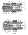
- Figs. 1 and 2 show a spring collet 1 integrated within a spindle assembly 100, which is part of a rework spindle, including a clamping sleeve 20 connected to a clamping piston 40, on the right of the Figs., indicating the rear, that is, rearward of the spring collet 1, a fixed sleeve 60 on which are mounted roller bearings 70, a clamping nut 30, on the left of the Figs., indicating the front, that is, to the front with the spring collet 1, and an elastic organ 50.
- the elastic organ 50 rests, on one side, against a face (not shown) of the sleeve 20 and, on the other side, against the rear face 19 (shown in Fig.
- the spring collet 1 constitutes an integral portion of the spindle assembly 100.
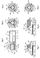
- the spring collet 1 with a central longitudinal axis designated as 1A in the Figs., is generally tubular in form, in the sense that it consists of a hollow body forming a hollow internal space, as represented in an axial section, and in a closed position, in Fig. 3 .
- a base 3 oriented toward the front
- a lateral tapering surface 4 with respectively, on one side a nose 5, and on the other side, a span 6.
- a rear portion 6A of the span 6 remains guided by the clamping sleeve 20 (see also Figs. 1 and 2 ).
- the outside diameter of the span 6 extends, according to the construction thereof, over a range of several millimeters, more or less, like the diameter of the nose 5.
- the hollow internal space is essentially composed of a variable central axial opening 7 and a relief 8.
- the periphery of the variable central axial opening 7 is provided, according to the example, with a carbide insert 9, which is applied to the workpiece 10 ( Figs. 1 and 2 ).
- the spring collet 1 according to the example, has three blind grooves 11; 12, where the grooves 11 ( Fig. 4 ) and 12 ( Figs. 5 and 6 ) correspond respectively to two different embodiments.
- Each pair of median planes 11 P; 12 P of the grooves it; 12 forms an angle of 120° (shown only once, in Figure 4 ).
- grooves 11; 12 open, to the front, onto a face 18 of the spring collet 1 and end in the formation of three clamping jaws 14; 15 - or, more generally, of as many clamping jaws as there are grooves, whereby the clamping jaws are capable of opening and of closing by virtue of their elasticity.
- the grooves 11; 12 open into hollows 13, which enable improved elasticity.
- the sleeve 20 translates forward (or backward) along a limited axial course length designated in Fig. 2 by the letter c (translation of the front face 22 that is perpendicular to the axis 1A).
- This axial course length c is a function of the characteristics of the machine tool within the spindle wherein the spring collet is mounted, it being noted that, in practice, the most customary values for the axial course length c run between approximately 1 mm and 3 mm.
- the first problem is solved by means pertaining to the geometric configuration of the collar 2, which are explained further below.
- the axial length of the collar 2, or collar root width 2 is determined as a function of the axial course length c. Accordingly, this function is chosen so that the length ⁇ can be selected within an interval limited by approximately twice (lower limit) and five times (upper limit) the length of the axial course length c. Knowing that the usual values of such axial course lengths c of sleeves 20 extend within a range of approximately about 1 mm to about 3 mm, then the length ⁇ will be selected within a range extending between approximately 2 mm and 15 mm. Experience has shown that, according to the diameter for which the spring collet is intended, the axial length ⁇ of the collar 2 is advantageously chosen between 3 mm and 9 mm.
- the conicity of the tapering surface 4 is dictated by the axial length ⁇ and by the diameter of the span 6 of the sleeve 20 at the intersection 2B of the tapering surface 4 with the sleeve 20, as seen in Fig. 3 .
- the selected angle ⁇ must always be greater than 15°.
- the angle ⁇ of the tapering surface 4 of the collar 2 is advantageously selected as 45°.
- the profile of the tapering surface 4 of the collar 2 may be curved (profile 4A of Fig. 7 ), or curved with at least one flat portion (profile 4B of Fig. 8 , the flat portion being shown by a line 4M).
- the overall slope of the surfaces 4A, 4B is indicated by the uniform reference generatrix line 4P, which supports the right hand segment 2A - 2B (same references numbers as those indicated in Fig. 3 ), a generatrix which, together with the axis 1A, forms angles ⁇ A and ⁇ B respectively.
- the corresponding face of the sleeve 20 presents a similar matching profile for each case.
- This configuration has the advantage of a better distribution of the force exerted on the collar 2, whereas, in order to produce the same effect - that is, for the same opening of the clamping jaws 14; 15 - the pressure necessary to be applied to the clamping jaws will be lower.
- a second means which can be combined with those described above, consists of increasing the number of grooves 11; 12.
- the determination of the maximum number of grooves depends on mechanical considerations concerning construction and/or manufacture. This increase will again enable a reduction of the force necessary to be applied to the collar 2 in order to obtain the same opening of the clamping jaws 14; 15.
- the diameters 10B, 10C can be as large as 1.60 mm, 7.50 mm or 13.00 mm respectively, without confronting the operator with any problem of a type which would require ancillary manipulations.
- the second disadvantage, or second problem it is solved according to an embodiment of the invention, through a modification of the geometry of the grooves ( Figs. 5 and 6 ).
- the spring collet 1 when the spring collet 1 is in the closed position (that is, when the workpiece is clamped), there remains a gap between the two mutually opposite faces (not shown) of each groove 11 ( Fig. 3 ), and an increase of the clamping force remains possible.
- the modification described above is determined, in each particular case, as a function of the parameters detailed above (tubular workpiece, presence of threading, etc.). In other words, for an admissible - that is, pre-calculated - clamping force, taking into account the aforementioned parameters, the gap between the grooves is corrected (see Fig.
- This correction consists of providing a gap ⁇ over the groups 12, at least over a defined radial distance thereof (indicated as 12R on one of the three grooves in Fig. 5 , the portions of groups 12R opening onto the variable axial opening 7 and partially onto the relief 8 ( Fig. 3 )).
- the gap ⁇ is calculated so that, when the spring collet 1 is in the closed position ( Fig. 6 ), and is thus exerting the predetermined clamping force on the workpiece 10 to be machined, then the mutually opposite faces of the portions of the grooves 12R abut against each other, thus making impossible any increase in clamping force.
- the workpiece 10 will thus be protected from any damage due to unintentional crushing.
- the spring collet 1 may retain the workpiece 10, with any appropriate insert, or without the intermediary of any insert, and thus without the intermediary of a carbide insert 9. Rather, the scope of the present invention is defined by the appended claims.
Landscapes
- Engineering & Computer Science (AREA)
- Mechanical Engineering (AREA)
- Gripping On Spindles (AREA)
- Jigs For Machine Tools (AREA)
Applications Claiming Priority (3)
| Application Number | Priority Date | Filing Date | Title |
|---|---|---|---|
| CH8452002 | 2002-05-21 | ||
| CH8452002 | 2002-05-21 | ||
| PCT/IL2003/000406 WO2003097278A1 (en) | 2002-05-21 | 2003-05-19 | Spring collet for machine tools |
Publications (3)
| Publication Number | Publication Date |
|---|---|
| EP1551584A1 EP1551584A1 (en) | 2005-07-13 |
| EP1551584A4 EP1551584A4 (en) | 2010-03-24 |
| EP1551584B1 true EP1551584B1 (en) | 2012-06-06 |
Family
ID=29426144
Family Applications (1)
| Application Number | Title | Priority Date | Filing Date |
|---|---|---|---|
| EP03725551A Expired - Lifetime EP1551584B1 (en) | 2002-05-21 | 2003-05-19 | Spring collet for machine tools |
Country Status (7)
| Country | Link |
|---|---|
| US (1) | US7036409B2 (da) |
| EP (1) | EP1551584B1 (da) |
| JP (1) | JP2006500227A (da) |
| AU (1) | AU2003228081A1 (da) |
| DK (1) | DK1551584T3 (da) |
| ES (1) | ES2386633T3 (da) |
| WO (1) | WO2003097278A1 (da) |
Families Citing this family (7)
| Publication number | Priority date | Publication date | Assignee | Title |
|---|---|---|---|---|
| GB0311852D0 (en) * | 2003-05-22 | 2003-06-25 | Westwind Air Bearings Ltd | Rotary tool holder assemblies |
| DE102004003778B4 (de) * | 2004-01-23 | 2008-01-31 | Robert Schröder GmbH & Co. KG | Spannfutter |
| US9446462B2 (en) * | 2008-03-10 | 2016-09-20 | Brasscraft Manufacturing Company | Material cutter clamping collet |
| TW201114542A (en) * | 2009-10-26 | 2011-05-01 | xuan-long Wu | Chuck device with top center and machine tool having the chuck device |
| US9511423B2 (en) * | 2013-11-22 | 2016-12-06 | Masa Tool, Inc. | Adapter enabling small draw-type collet to operate as stationary-type collet in large lathe spindle sleeve |
| CN107744919A (zh) * | 2017-11-23 | 2018-03-02 | 南京工业职业技术学院 | 一种自定心可旋转夹具 |
| CN117300674B (zh) * | 2023-11-28 | 2024-04-16 | 宁波吉烨汽配模具有限公司 | 一种车床加工用便捷锁紧夹具 |
Family Cites Families (18)
| Publication number | Priority date | Publication date | Assignee | Title |
|---|---|---|---|---|
| US232311A (en) * | 1880-09-14 | stare | ||
| DE434583C (de) * | 1925-11-04 | 1926-09-25 | Otto Seidemann | Zangenspannfutter |
| DE974660C (de) * | 1944-02-03 | 1961-03-16 | Ortlieb & Cie Julius | Schnellspannvorrichtung |
| US2475519A (en) * | 1946-07-26 | 1949-07-05 | Waterbury Farrel Foundry Co | Chucking apparatus |
| US2438797A (en) * | 1946-11-12 | 1948-03-30 | Bagge Kaj | Portable small hand tool vise |
| FR954717A (da) * | 1946-12-06 | 1950-01-05 | ||
| FR1019344A (fr) * | 1949-07-02 | 1953-01-20 | Schaublin | Dispositif de serrage pour pinces fendues d'une machine-outil |
| US2989316A (en) * | 1958-06-30 | 1961-06-20 | Perry Fay Company | Pick off chuck |
| US3121572A (en) * | 1961-11-07 | 1964-02-18 | Torok Frank | Tool construction |
| US3874688A (en) * | 1974-04-04 | 1975-04-01 | Norman E Schiller | Collet adapter |
| DE3006476A1 (de) * | 1980-02-21 | 1981-09-03 | Willi Ing.(grad.) 4010 Hilden Eichholz | Spannzange mit innenliegendem fuehrungsrohr |
| DE3630808A1 (de) * | 1986-09-10 | 1988-03-17 | Manfred Kappler | Spannzange |
| JPS6411701A (en) * | 1987-07-06 | 1989-01-17 | Suganuma Sangyo Kk | Method of automatically inserting profile into automatic lathe and device therefor |
| JP2821644B2 (ja) * | 1990-06-15 | 1998-11-05 | 理研精機株式会社 | コレットチャック嵌着装置の製造方法 |
| JPH08229714A (ja) * | 1995-02-24 | 1996-09-10 | Alps Tool:Kk | チャック装置 |
| JP2000158216A (ja) * | 1998-11-20 | 2000-06-13 | Tsugami Tool:Kk | コレットチャック及びチャック装置 |
| JP4471450B2 (ja) * | 2000-05-12 | 2010-06-02 | シチズンホールディングス株式会社 | 棒材把持装置及び自動旋盤 |
| US6508475B1 (en) * | 2001-10-31 | 2003-01-21 | Hudson Precision Products Co. | Holding apparatus with improved retention ability and method of holding a tool |
-
2003
- 2003-05-19 DK DK03725551.0T patent/DK1551584T3/da active
- 2003-05-19 ES ES03725551T patent/ES2386633T3/es not_active Expired - Lifetime
- 2003-05-19 AU AU2003228081A patent/AU2003228081A1/en not_active Abandoned
- 2003-05-19 WO PCT/IL2003/000406 patent/WO2003097278A1/en not_active Ceased
- 2003-05-19 EP EP03725551A patent/EP1551584B1/en not_active Expired - Lifetime
- 2003-05-19 JP JP2004504661A patent/JP2006500227A/ja active Pending
-
2004
- 2004-11-15 US US10/990,179 patent/US7036409B2/en not_active Expired - Fee Related
Also Published As
| Publication number | Publication date |
|---|---|
| WO2003097278A1 (en) | 2003-11-27 |
| US20050087936A1 (en) | 2005-04-28 |
| EP1551584A4 (en) | 2010-03-24 |
| DK1551584T3 (da) | 2012-09-17 |
| US7036409B2 (en) | 2006-05-02 |
| ES2386633T3 (es) | 2012-08-24 |
| EP1551584A1 (en) | 2005-07-13 |
| AU2003228081A1 (en) | 2003-12-02 |
| JP2006500227A (ja) | 2006-01-05 |
Similar Documents
| Publication | Publication Date | Title |
|---|---|---|
| US5997012A (en) | Differential thread control of chuck gripping of work | |
| US4275893A (en) | Self-tightening keyless chuck | |
| JP5011366B2 (ja) | 工具ホルダおよび工具ホルダの組立方法 | |
| US6371705B1 (en) | Tool holder | |
| US5398947A (en) | Self-aligning collet | |
| US7281307B2 (en) | Tap process for hard workpieces | |
| EP1551584B1 (en) | Spring collet for machine tools | |
| US6332619B1 (en) | Derosa router chuck | |
| US7758289B2 (en) | Diameter-compensating bush for a tool holder | |
| JP4589304B2 (ja) | 工具受容要素およびその位置決めのためのアダプター | |
| US20030047891A1 (en) | Collet adapter | |
| US5615590A (en) | Guide collet adaptor for radial jaw chuck lathes | |
| GB2059829A (en) | Drill chuck with cutting edges | |
| JP2572190B2 (ja) | 管材用テーパねじ転造機 | |
| JP2000158216A (ja) | コレットチャック及びチャック装置 | |
| CN215746897U (zh) | 普通车床仿套丝机加工装置 | |
| CN113618171A (zh) | 普通车床仿套丝机加工装置及方法 | |
| US3720416A (en) | Adjustable work stop for turning machine | |
| JPS58171230A (ja) | 回転工具保持具 | |
| JP2007168003A (ja) | 工具ホルダ | |
| US5692422A (en) | Squaring machine | |
| CN216502383U (zh) | 一种可控制转动的车床尾座连接座夹套 | |
| GB2233058A (en) | Lockable nuts | |
| EP0079700A2 (en) | Cutting tools | |
| JPH0641762Y2 (ja) | 自動旋盤機の加工物保持装置 |
Legal Events
| Date | Code | Title | Description |
|---|---|---|---|
| PUAI | Public reference made under article 153(3) epc to a published international application that has entered the european phase |
Free format text: ORIGINAL CODE: 0009012 |
|
| 17P | Request for examination filed |
Effective date: 20041221 |
|
| AK | Designated contracting states |
Kind code of ref document: A1 Designated state(s): AT BE BG CH CY CZ DE DK EE ES FI FR GB GR HU IE IT LI LU MC NL PT RO SE SI SK TR |
|
| AX | Request for extension of the european patent |
Extension state: AL LT LV MK |
|
| DAX | Request for extension of the european patent (deleted) | ||
| A4 | Supplementary search report drawn up and despatched |
Effective date: 20100224 |
|
| 17Q | First examination report despatched |
Effective date: 20100930 |
|
| GRAP | Despatch of communication of intention to grant a patent |
Free format text: ORIGINAL CODE: EPIDOSNIGR1 |
|
| GRAS | Grant fee paid |
Free format text: ORIGINAL CODE: EPIDOSNIGR3 |
|
| GRAA | (expected) grant |
Free format text: ORIGINAL CODE: 0009210 |
|
| AK | Designated contracting states |
Kind code of ref document: B1 Designated state(s): AT BE BG CH CY CZ DE DK EE ES FI FR GB GR HU IE IT LI LU MC NL PT RO SE SI SK TR |
|
| REG | Reference to a national code |
Ref country code: GB Ref legal event code: FG4D |
|
| REG | Reference to a national code |
Ref country code: CH Ref legal event code: EP Ref country code: AT Ref legal event code: REF Ref document number: 560764 Country of ref document: AT Kind code of ref document: T Effective date: 20120615 |
|
| REG | Reference to a national code |
Ref country code: IE Ref legal event code: FG4D |
|
| REG | Reference to a national code |
Ref country code: DE Ref legal event code: R096 Ref document number: 60341147 Country of ref document: DE Effective date: 20120802 |
|
| REG | Reference to a national code |
Ref country code: NL Ref legal event code: T3 |
|
| REG | Reference to a national code |
Ref country code: ES Ref legal event code: FG2A Ref document number: 2386633 Country of ref document: ES Kind code of ref document: T3 Effective date: 20120824 |
|
| REG | Reference to a national code |
Ref country code: DK Ref legal event code: T3 |
|
| REG | Reference to a national code |
Ref country code: SE Ref legal event code: TRGR |
|
| PG25 | Lapsed in a contracting state [announced via postgrant information from national office to epo] |
Ref country code: FI Free format text: LAPSE BECAUSE OF FAILURE TO SUBMIT A TRANSLATION OF THE DESCRIPTION OR TO PAY THE FEE WITHIN THE PRESCRIBED TIME-LIMIT Effective date: 20120606 Ref country code: CY Free format text: LAPSE BECAUSE OF FAILURE TO SUBMIT A TRANSLATION OF THE DESCRIPTION OR TO PAY THE FEE WITHIN THE PRESCRIBED TIME-LIMIT Effective date: 20120606 |
|
| PG25 | Lapsed in a contracting state [announced via postgrant information from national office to epo] |
Ref country code: SI Free format text: LAPSE BECAUSE OF FAILURE TO SUBMIT A TRANSLATION OF THE DESCRIPTION OR TO PAY THE FEE WITHIN THE PRESCRIBED TIME-LIMIT Effective date: 20120606 Ref country code: GR Free format text: LAPSE BECAUSE OF FAILURE TO SUBMIT A TRANSLATION OF THE DESCRIPTION OR TO PAY THE FEE WITHIN THE PRESCRIBED TIME-LIMIT Effective date: 20120907 |
|
| PG25 | Lapsed in a contracting state [announced via postgrant information from national office to epo] |
Ref country code: SK Free format text: LAPSE BECAUSE OF FAILURE TO SUBMIT A TRANSLATION OF THE DESCRIPTION OR TO PAY THE FEE WITHIN THE PRESCRIBED TIME-LIMIT Effective date: 20120606 Ref country code: RO Free format text: LAPSE BECAUSE OF FAILURE TO SUBMIT A TRANSLATION OF THE DESCRIPTION OR TO PAY THE FEE WITHIN THE PRESCRIBED TIME-LIMIT Effective date: 20120606 Ref country code: EE Free format text: LAPSE BECAUSE OF FAILURE TO SUBMIT A TRANSLATION OF THE DESCRIPTION OR TO PAY THE FEE WITHIN THE PRESCRIBED TIME-LIMIT Effective date: 20120606 |
|
| PG25 | Lapsed in a contracting state [announced via postgrant information from national office to epo] |
Ref country code: PT Free format text: LAPSE BECAUSE OF FAILURE TO SUBMIT A TRANSLATION OF THE DESCRIPTION OR TO PAY THE FEE WITHIN THE PRESCRIBED TIME-LIMIT Effective date: 20121008 |
|
| PLBE | No opposition filed within time limit |
Free format text: ORIGINAL CODE: 0009261 |
|
| STAA | Information on the status of an ep patent application or granted ep patent |
Free format text: STATUS: NO OPPOSITION FILED WITHIN TIME LIMIT |
|
| 26N | No opposition filed |
Effective date: 20130307 |
|
| REG | Reference to a national code |
Ref country code: DE Ref legal event code: R097 Ref document number: 60341147 Country of ref document: DE Effective date: 20130307 |
|
| PG25 | Lapsed in a contracting state [announced via postgrant information from national office to epo] |
Ref country code: BG Free format text: LAPSE BECAUSE OF FAILURE TO SUBMIT A TRANSLATION OF THE DESCRIPTION OR TO PAY THE FEE WITHIN THE PRESCRIBED TIME-LIMIT Effective date: 20120906 |
|
| PG25 | Lapsed in a contracting state [announced via postgrant information from national office to epo] |
Ref country code: MC Free format text: LAPSE BECAUSE OF FAILURE TO SUBMIT A TRANSLATION OF THE DESCRIPTION OR TO PAY THE FEE WITHIN THE PRESCRIBED TIME-LIMIT Effective date: 20120606 |
|
| PG25 | Lapsed in a contracting state [announced via postgrant information from national office to epo] |
Ref country code: LU Free format text: LAPSE BECAUSE OF NON-PAYMENT OF DUE FEES Effective date: 20130519 Ref country code: HU Free format text: LAPSE BECAUSE OF FAILURE TO SUBMIT A TRANSLATION OF THE DESCRIPTION OR TO PAY THE FEE WITHIN THE PRESCRIBED TIME-LIMIT; INVALID AB INITIO Effective date: 20030519 |
|
| PGFP | Annual fee paid to national office [announced via postgrant information from national office to epo] |
Ref country code: AT Payment date: 20150521 Year of fee payment: 13 Ref country code: NL Payment date: 20150520 Year of fee payment: 13 Ref country code: BE Payment date: 20150520 Year of fee payment: 13 Ref country code: IE Payment date: 20150514 Year of fee payment: 13 |
|
| REG | Reference to a national code |
Ref country code: FR Ref legal event code: PLFP Year of fee payment: 14 |
|
| PGFP | Annual fee paid to national office [announced via postgrant information from national office to epo] |
Ref country code: ES Payment date: 20160512 Year of fee payment: 14 Ref country code: GB Payment date: 20160520 Year of fee payment: 14 Ref country code: DE Payment date: 20160520 Year of fee payment: 14 Ref country code: CZ Payment date: 20160517 Year of fee payment: 14 |
|
| PG25 | Lapsed in a contracting state [announced via postgrant information from national office to epo] |
Ref country code: BE Free format text: LAPSE BECAUSE OF NON-PAYMENT OF DUE FEES Effective date: 20160531 |
|
| PGFP | Annual fee paid to national office [announced via postgrant information from national office to epo] |
Ref country code: DK Payment date: 20160519 Year of fee payment: 14 Ref country code: IT Payment date: 20160524 Year of fee payment: 14 Ref country code: FR Payment date: 20160520 Year of fee payment: 14 Ref country code: TR Payment date: 20160421 Year of fee payment: 14 Ref country code: SE Payment date: 20160519 Year of fee payment: 14 |
|
| REG | Reference to a national code |
Ref country code: NL Ref legal event code: MM Effective date: 20160601 |
|
| REG | Reference to a national code |
Ref country code: AT Ref legal event code: MM01 Ref document number: 560764 Country of ref document: AT Kind code of ref document: T Effective date: 20160519 |
|
| REG | Reference to a national code |
Ref country code: IE Ref legal event code: MM4A |
|
| PG25 | Lapsed in a contracting state [announced via postgrant information from national office to epo] |
Ref country code: NL Free format text: LAPSE BECAUSE OF NON-PAYMENT OF DUE FEES Effective date: 20160601 Ref country code: AT Free format text: LAPSE BECAUSE OF NON-PAYMENT OF DUE FEES Effective date: 20160519 |
|
| PG25 | Lapsed in a contracting state [announced via postgrant information from national office to epo] |
Ref country code: IE Free format text: LAPSE BECAUSE OF NON-PAYMENT OF DUE FEES Effective date: 20160519 |
|
| REG | Reference to a national code |
Ref country code: DE Ref legal event code: R119 Ref document number: 60341147 Country of ref document: DE |
|
| REG | Reference to a national code |
Ref country code: SE Ref legal event code: EUG Ref country code: DK Ref legal event code: EBP Effective date: 20170531 |
|
| GBPC | Gb: european patent ceased through non-payment of renewal fee |
Effective date: 20170519 |
|
| PG25 | Lapsed in a contracting state [announced via postgrant information from national office to epo] |
Ref country code: CZ Free format text: LAPSE BECAUSE OF NON-PAYMENT OF DUE FEES Effective date: 20170519 |
|
| PG25 | Lapsed in a contracting state [announced via postgrant information from national office to epo] |
Ref country code: SE Free format text: LAPSE BECAUSE OF NON-PAYMENT OF DUE FEES Effective date: 20170520 |
|
| REG | Reference to a national code |
Ref country code: FR Ref legal event code: ST Effective date: 20180131 |
|
| PG25 | Lapsed in a contracting state [announced via postgrant information from national office to epo] |
Ref country code: DK Free format text: LAPSE BECAUSE OF NON-PAYMENT OF DUE FEES Effective date: 20170531 Ref country code: GB Free format text: LAPSE BECAUSE OF NON-PAYMENT OF DUE FEES Effective date: 20170519 Ref country code: DE Free format text: LAPSE BECAUSE OF NON-PAYMENT OF DUE FEES Effective date: 20171201 |
|
| PG25 | Lapsed in a contracting state [announced via postgrant information from national office to epo] |
Ref country code: FR Free format text: LAPSE BECAUSE OF NON-PAYMENT OF DUE FEES Effective date: 20170531 Ref country code: IT Free format text: LAPSE BECAUSE OF NON-PAYMENT OF DUE FEES Effective date: 20170519 |
|
| REG | Reference to a national code |
Ref country code: ES Ref legal event code: FD2A Effective date: 20180629 |
|
| PG25 | Lapsed in a contracting state [announced via postgrant information from national office to epo] |
Ref country code: ES Free format text: LAPSE BECAUSE OF NON-PAYMENT OF DUE FEES Effective date: 20170520 |
|
| PGFP | Annual fee paid to national office [announced via postgrant information from national office to epo] |
Ref country code: CH Payment date: 20200731 Year of fee payment: 18 |
|
| REG | Reference to a national code |
Ref country code: CH Ref legal event code: PL |
|
| PG25 | Lapsed in a contracting state [announced via postgrant information from national office to epo] |
Ref country code: CH Free format text: LAPSE BECAUSE OF NON-PAYMENT OF DUE FEES Effective date: 20210531 Ref country code: LI Free format text: LAPSE BECAUSE OF NON-PAYMENT OF DUE FEES Effective date: 20210531 |
|
| PG25 | Lapsed in a contracting state [announced via postgrant information from national office to epo] |
Ref country code: TR Free format text: LAPSE BECAUSE OF NON-PAYMENT OF DUE FEES Effective date: 20170519 |