EP1551646B1 - Verringerung von drehschwingungen in radsätzen von schienenfahrzeugen - Google Patents
Verringerung von drehschwingungen in radsätzen von schienenfahrzeugen Download PDFInfo
- Publication number
- EP1551646B1 EP1551646B1 EP03764089A EP03764089A EP1551646B1 EP 1551646 B1 EP1551646 B1 EP 1551646B1 EP 03764089 A EP03764089 A EP 03764089A EP 03764089 A EP03764089 A EP 03764089A EP 1551646 B1 EP1551646 B1 EP 1551646B1
- Authority
- EP
- European Patent Office
- Prior art keywords
- wheel
- wheel set
- set according
- mass
- axle
- Prior art date
- Legal status (The legal status is an assumption and is not a legal conclusion. Google has not performed a legal analysis and makes no representation as to the accuracy of the status listed.)
- Expired - Lifetime
Links
- 238000000034 method Methods 0.000 claims abstract description 10
- 238000013016 damping Methods 0.000 claims description 12
- 230000006835 compression Effects 0.000 claims description 11
- 238000007906 compression Methods 0.000 claims description 11
- 230000033001 locomotion Effects 0.000 claims description 11
- 230000010355 oscillation Effects 0.000 claims description 3
- 238000003780 insertion Methods 0.000 claims description 2
- 230000037431 insertion Effects 0.000 claims description 2
- 230000003534 oscillatory effect Effects 0.000 claims 3
- 230000000694 effects Effects 0.000 description 9
- 238000010276 construction Methods 0.000 description 6
- 229910000639 Spring steel Inorganic materials 0.000 description 5
- 239000000853 adhesive Substances 0.000 description 3
- 230000001070 adhesive effect Effects 0.000 description 3
- 230000001965 increasing effect Effects 0.000 description 3
- 230000002265 prevention Effects 0.000 description 3
- XEEYBQQBJWHFJM-UHFFFAOYSA-N Iron Chemical compound [Fe] XEEYBQQBJWHFJM-UHFFFAOYSA-N 0.000 description 2
- 238000010521 absorption reaction Methods 0.000 description 2
- 239000011248 coating agent Substances 0.000 description 2
- 238000000576 coating method Methods 0.000 description 2
- 238000010438 heat treatment Methods 0.000 description 2
- 239000002184 metal Substances 0.000 description 2
- 229910052751 metal Inorganic materials 0.000 description 2
- 238000012546 transfer Methods 0.000 description 2
- 238000004073 vulcanization Methods 0.000 description 2
- 238000003466 welding Methods 0.000 description 2
- 230000001133 acceleration Effects 0.000 description 1
- 230000001154 acute effect Effects 0.000 description 1
- 229910045601 alloy Inorganic materials 0.000 description 1
- 239000000956 alloy Substances 0.000 description 1
- 238000005452 bending Methods 0.000 description 1
- 230000005540 biological transmission Effects 0.000 description 1
- 230000015556 catabolic process Effects 0.000 description 1
- 239000002131 composite material Substances 0.000 description 1
- 230000001419 dependent effect Effects 0.000 description 1
- 230000001627 detrimental effect Effects 0.000 description 1
- 230000009977 dual effect Effects 0.000 description 1
- 230000002708 enhancing effect Effects 0.000 description 1
- 239000004519 grease Substances 0.000 description 1
- 230000020169 heat generation Effects 0.000 description 1
- 229910052742 iron Inorganic materials 0.000 description 1
- 230000007774 longterm Effects 0.000 description 1
- 238000012423 maintenance Methods 0.000 description 1
- 239000000463 material Substances 0.000 description 1
- 238000005259 measurement Methods 0.000 description 1
- 238000005498 polishing Methods 0.000 description 1
- 239000004810 polytetrafluoroethylene Substances 0.000 description 1
- 229920001343 polytetrafluoroethylene Polymers 0.000 description 1
- 230000036316 preload Effects 0.000 description 1
- 238000002360 preparation method Methods 0.000 description 1
- 238000003825 pressing Methods 0.000 description 1
- 230000035939 shock Effects 0.000 description 1
- 230000006641 stabilisation Effects 0.000 description 1
- 238000010792 warming Methods 0.000 description 1
Images


Classifications
-
- F—MECHANICAL ENGINEERING; LIGHTING; HEATING; WEAPONS; BLASTING
- F16—ENGINEERING ELEMENTS AND UNITS; GENERAL MEASURES FOR PRODUCING AND MAINTAINING EFFECTIVE FUNCTIONING OF MACHINES OR INSTALLATIONS; THERMAL INSULATION IN GENERAL
- F16F—SPRINGS; SHOCK-ABSORBERS; MEANS FOR DAMPING VIBRATION
- F16F15/00—Suppression of vibrations in systems; Means or arrangements for avoiding or reducing out-of-balance forces, e.g. due to motion
- F16F15/10—Suppression of vibrations in rotating systems by making use of members moving with the system
- F16F15/14—Suppression of vibrations in rotating systems by making use of members moving with the system using masses freely rotating with the system, i.e. uninvolved in transmitting driveline torque, e.g. rotative dynamic dampers
- F16F15/1407—Suppression of vibrations in rotating systems by making use of members moving with the system using masses freely rotating with the system, i.e. uninvolved in transmitting driveline torque, e.g. rotative dynamic dampers the rotation being limited with respect to the driving means
- F16F15/1414—Masses driven by elastic elements
-
- B—PERFORMING OPERATIONS; TRANSPORTING
- B60—VEHICLES IN GENERAL
- B60B—VEHICLE WHEELS; CASTORS; AXLES FOR WHEELS OR CASTORS; INCREASING WHEEL ADHESION
- B60B17/00—Wheels characterised by rail-engaging elements
- B60B17/0006—Construction of wheel bodies, e.g. disc wheels
-
- B—PERFORMING OPERATIONS; TRANSPORTING
- B60—VEHICLES IN GENERAL
- B60B—VEHICLE WHEELS; CASTORS; AXLES FOR WHEELS OR CASTORS; INCREASING WHEEL ADHESION
- B60B17/00—Wheels characterised by rail-engaging elements
- B60B17/0006—Construction of wheel bodies, e.g. disc wheels
- B60B17/0013—Construction of wheel bodies, e.g. disc wheels formed by two or more axially spaced discs
- B60B17/0017—Construction of wheel bodies, e.g. disc wheels formed by two or more axially spaced discs with insonorisation means
-
- B—PERFORMING OPERATIONS; TRANSPORTING
- B60—VEHICLES IN GENERAL
- B60B—VEHICLE WHEELS; CASTORS; AXLES FOR WHEELS OR CASTORS; INCREASING WHEEL ADHESION
- B60B17/00—Wheels characterised by rail-engaging elements
- B60B17/0027—Resilient wheels, e.g. resilient hubs
- B60B17/0031—Resilient wheels, e.g. resilient hubs using springs
- B60B17/0034—Resilient wheels, e.g. resilient hubs using springs of rubber or other non-metallic material
- B60B17/0041—Resilient wheels, e.g. resilient hubs using springs of rubber or other non-metallic material of substantially rectangular cross section
-
- B—PERFORMING OPERATIONS; TRANSPORTING
- B60—VEHICLES IN GENERAL
- B60B—VEHICLE WHEELS; CASTORS; AXLES FOR WHEELS OR CASTORS; INCREASING WHEEL ADHESION
- B60B17/00—Wheels characterised by rail-engaging elements
- B60B17/0055—Wheels characterised by rail-engaging elements with non-elastic tyres (e.g. of particular profile or composition)
- B60B17/0058—Wheels characterised by rail-engaging elements with non-elastic tyres (e.g. of particular profile or composition) characterised by their fixing to wheel bodies
-
- B—PERFORMING OPERATIONS; TRANSPORTING
- B60—VEHICLES IN GENERAL
- B60B—VEHICLE WHEELS; CASTORS; AXLES FOR WHEELS OR CASTORS; INCREASING WHEEL ADHESION
- B60B17/00—Wheels characterised by rail-engaging elements
- B60B17/0055—Wheels characterised by rail-engaging elements with non-elastic tyres (e.g. of particular profile or composition)
- B60B17/0062—Wheels characterised by rail-engaging elements with non-elastic tyres (e.g. of particular profile or composition) having teeth or protrusions on the circumference of the wheel
-
- B—PERFORMING OPERATIONS; TRANSPORTING
- B60—VEHICLES IN GENERAL
- B60B—VEHICLE WHEELS; CASTORS; AXLES FOR WHEELS OR CASTORS; INCREASING WHEEL ADHESION
- B60B17/00—Wheels characterised by rail-engaging elements
- B60B17/0065—Flange details
- B60B17/0068—Flange details the flange being provided on a single side
-
- F—MECHANICAL ENGINEERING; LIGHTING; HEATING; WEAPONS; BLASTING
- F16—ENGINEERING ELEMENTS AND UNITS; GENERAL MEASURES FOR PRODUCING AND MAINTAINING EFFECTIVE FUNCTIONING OF MACHINES OR INSTALLATIONS; THERMAL INSULATION IN GENERAL
- F16D—COUPLINGS FOR TRANSMITTING ROTATION; CLUTCHES; BRAKES
- F16D65/00—Parts or details
- F16D65/0006—Noise or vibration control
- F16D65/0018—Dynamic vibration dampers, e.g. mass-spring systems
-
- F—MECHANICAL ENGINEERING; LIGHTING; HEATING; WEAPONS; BLASTING
- F16—ENGINEERING ELEMENTS AND UNITS; GENERAL MEASURES FOR PRODUCING AND MAINTAINING EFFECTIVE FUNCTIONING OF MACHINES OR INSTALLATIONS; THERMAL INSULATION IN GENERAL
- F16D—COUPLINGS FOR TRANSMITTING ROTATION; CLUTCHES; BRAKES
- F16D65/00—Parts or details
- F16D65/02—Braking members; Mounting thereof
- F16D65/12—Discs; Drums for disc brakes
- F16D65/123—Discs; Drums for disc brakes comprising an annular disc secured to a hub member; Discs characterised by means for mounting
- F16D65/124—Discs; Drums for disc brakes comprising an annular disc secured to a hub member; Discs characterised by means for mounting adapted for mounting on the wheel of a railway vehicle
-
- F—MECHANICAL ENGINEERING; LIGHTING; HEATING; WEAPONS; BLASTING
- F16—ENGINEERING ELEMENTS AND UNITS; GENERAL MEASURES FOR PRODUCING AND MAINTAINING EFFECTIVE FUNCTIONING OF MACHINES OR INSTALLATIONS; THERMAL INSULATION IN GENERAL
- F16F—SPRINGS; SHOCK-ABSORBERS; MEANS FOR DAMPING VIBRATION
- F16F15/00—Suppression of vibrations in systems; Means or arrangements for avoiding or reducing out-of-balance forces, e.g. due to motion
- F16F15/10—Suppression of vibrations in rotating systems by making use of members moving with the system
- F16F15/12—Suppression of vibrations in rotating systems by making use of members moving with the system using elastic members or friction-damping members, e.g. between a rotating shaft and a gyratory mass mounted thereon
-
- F—MECHANICAL ENGINEERING; LIGHTING; HEATING; WEAPONS; BLASTING
- F16—ENGINEERING ELEMENTS AND UNITS; GENERAL MEASURES FOR PRODUCING AND MAINTAINING EFFECTIVE FUNCTIONING OF MACHINES OR INSTALLATIONS; THERMAL INSULATION IN GENERAL
- F16D—COUPLINGS FOR TRANSMITTING ROTATION; CLUTCHES; BRAKES
- F16D65/00—Parts or details
- F16D65/02—Braking members; Mounting thereof
- F16D2065/13—Parts or details of discs or drums
- F16D2065/134—Connection
- F16D2065/138—Connection to wheel
-
- F—MECHANICAL ENGINEERING; LIGHTING; HEATING; WEAPONS; BLASTING
- F16—ENGINEERING ELEMENTS AND UNITS; GENERAL MEASURES FOR PRODUCING AND MAINTAINING EFFECTIVE FUNCTIONING OF MACHINES OR INSTALLATIONS; THERMAL INSULATION IN GENERAL
- F16D—COUPLINGS FOR TRANSMITTING ROTATION; CLUTCHES; BRAKES
- F16D65/00—Parts or details
- F16D65/02—Braking members; Mounting thereof
- F16D2065/13—Parts or details of discs or drums
- F16D2065/134—Connection
- F16D2065/1392—Connection elements
Definitions
- the invention relates to methods and devices for the reduction or prevention of torsional vibrations and in particular to the reduction or prevention of such vibrations in the wheel sets of rail vehicles. It further relates to rail systems incorporating such devices and adapted to provide anti-slip control beyond the limits of currently, available systems.
- a wheel set according to the preamble of claim 1 is known from the closest prior art document US 1 765 477 A .
- the node is usually located at the centre point of the axle. Where the drive is also located at the centre of the axle, it experiences no effect from the vibration but can also not be used to influence it. Locating the drive off-centre can provide a certain degree of control over these vibrations and can cause a reduction therein. Under such circumstances it is possible to detect the vibration and to counteract it by appropriate motor control in a manner similar to that used in anti-lock braking systems.
- the constructional arrangement of the drive on the bogie or vehicle frame does not however always allow for off-centred positioning of the drive with respect to the axle. In diesel units, such high speed control is not presently possible and other means must be sought to counteract these torsional vibrations.
- Vibration absorbing devices have also been used in the context of rail vehicle wheel sets for other purposes.
- Document DE19501613 A discloses the use of a vibration reducing element attached to the flange of a rail vehicle wheel.
- the device is adapted to oscillate at high frequencies in the audible range in order to damp vibrations and reduce noise. Due to its relatively light construction it is unsuitable for the reduction of torsional vibrations of the complete wheel set, which requires a much greater mass in proportion to that of the wheel set itself.
- a wheel set for a rail vehicle comprising a pair of wheels connected by an axle, and further comprising a vibration absorbing device comprising a mass resiliently mounted on the wheel set and adapted to oscillate at the resonant frequency of torsional vibrations of the wheel/axle system.
- the present invention also foresees a method of preventing or reducing torsional vibrations in a wheel set of a rail vehicle comprising a pair of wheels connected by an axle, the method comprising determining the resonant frequency of torsional vibrations of the wheel/axle system and resiliently mounting a vibration absorbing device comprising a mass on the wheel set, the mass and its resilient mounting being selected to oscillate at or near that resonant frequency.
- the vibration absorbing means In order to maximise the effect of the vibration absorbing means, they should preferably be mounted at locations where the amplitude of vibrational motion is greatest, namely as far from the vibrational node as possible. It has been found that locating the vibration absorbing device at a radially outward location on the wheel is particularly advantageous in reducing this unwanted vibration of the wheel set at its fundamental frequency.
- the vibration absorbing device will operate effectively over a particular, narrow frequency range.
- the mass and inertia of the wheel set changes as a result of wearing down of the wheels there will come a point where the natural frequency of the torsional vibration lies outside this narrow band and the device will be unable to absorb effectively.
- the effective bandwidth of the vibration absorbing device is increased, allowing it to function effectively over a wider range of frequencies covering those values corresponding to all conditions of the wheel set e.g. the extremes of wear of the wheels. Excessive damping however, should be avoided as it has the effect of reducing the overall amplitude of vibration absorbed.
- the vibration absorbing device may comprise two brake disks located on either side of the wheel and connected by spring elements passing through the wheel.
- both brake disks may be connected by other connecting means e.g. screws directly to the wheel.
- Both brake disks may be provided with a surface in contact with the wheel, which is prepared to have a particular coefficient of friction to ensure adequate damping.
- the brake disks are used as a counter-oscillating mass.
- Special spring steel elements e.g. in the form of springs sleeves, provide the necessary elastic connection of the brake disk to the wheel. Even during active braking the counter vibration of the brake disk is still possible so that even with engaged brake shoes the function of the brake disk as a vibration absorbing device is maintained.
- the spring steel elements have a torsional stiffness that is so chosen, that together with the mass of the brake disk a harmonic frequency at the torsional frequency of the wheel set is achieved. In this way the torsional vibration of a wheel set is prevented by anti-phase vibration of the brake disks.
- the vibration absorbing device may comprise a metal ring or ring segments provided with a vulcanised rubber layer for attachment to the wheel.
- the ring is arranged at a radially outer extent of the wheel and may be attached by clamps, screws, bolts, adhesive or other means.
- the rotational mass of the damping device is matched to the stiffness of the rubber in order to match the natural frequency of the axle. At this natural frequency the damping device will be excited in anti-phase with the wheel vibrations, thereby preventing the occurrence of resonant effects.
- the vibration absorbing device of the present invention thus provides a simple and effective means for reducing torsional vibrations in rail vehicle wheel sets. It is simple in construction and requires no energy supply and little maintenance. It may be fitted to existing wheels and is suitable for use on both driven and non-driven wheel sets. Its independence from the drive system also allows the drive control system to be better adapted to anti-slip control since the operating parameters of such a control system need not then take into account the stabilisation of torsional vibration.
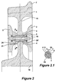
- Figure 1 illustrates an arrangement for the reduction or prevention of torsional vibrations in rail vehicle wheel sets.
- the wheel set comprises a pair of wheels 1 (of which one is illustrated) rigidly mounted to an axle 17.
- the mounting is nominally rigid, in the context of the present invention it should be noted that the axle is subject to torsional forces and can twist such that one wheel may rotate with respect to the other wheel. These oscillations depend on the construction of the wheel set and on the load conditions.
- Each wheel comprises a hub section 18 and a generally cylindrical rim 7 spaced apart by a flange 15 extending between the wheel rim 7 and the wheel hub 18.
- the wheel 1 is provided with two annular brake disks 2 arranged concentrically about the axle on either side of the flange 15.
- a single brake disk mounted on just one side of the flange 15 could also be considered.
- the region of contact between the flange 15 and the facing surface of the brake disk 2 advantageously comprises a prepared surface 3 having a particular coefficient of friction. Usually this surface should serve to reduce the friction between the two surfaces.
- the prepared surface 3 may be provided on the flange 15 or on the brake disk 2 or on both and may comprise any suitable means for reducing or enhancing friction or may involve the inclusion of an intermediate friction determining layer between the adjacent surfaces.
- Typical preparations may include polishing or coating.
- a coating or intermediate layer of PTFE has been found to be particularly effective.
- the region of contact between the flange 15 and the facing surface of the brake disk 2 also serves to provide damping.
- the amount of damping is determined by the coefficient of friction of the two surfaces and the force with which they are pressed together. In the present case, this force may vary as the brakes are applied causing the disks 2 to be pressed tighter against the flange 15.
- the two brake disks 2 are connected together by bolts 5 which extend through bores 21 in the flange 15.
- the attached figures illustrate crossections taken through a single bolt but it is to be understood that a number of bores 21 and corresponding bolts 5 are present, preferably arranged in a concentric circle around the wheel axle 17. As an example, eight bolts 5 per wheel may be used to ensure adequate securement of the brake disks. In the remaining description, only a single bolt assembly will be described.
- the bolt 5 is secured by a suitable nut 23.
- Suitable spring washers 19 or other means to prevent loosening of the nut 23 are arranged between the nut 23 and the brake disk 2 and between the bolt head 22 and the brake disk 2.
- the head 22 of the bolt 5 and the nut 23 are countersunk into the brake disk 2.
- Alternative forms of connecting element may also be used to achieve the same effect.
- the bolt 5 may be replaced by a threaded stub extending from the flange surface. In such an arrangement, appropriate friction reducing means could be required beneath the nut 23 in addition to the prepared surface 3 in order to ensure free movement of the brake disk.
- a spring sleeve 4 surrounds the bolt 5 and extends through the flange 15 and into a counter bore 20 in the brake disks 2.
- Alternative forms of spring element may also be used instead of spring sleeve 4, such as a coiled spring-steel shim.
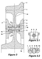
- FIG. 2 shows an alternative constructional arrangement of the vibration absorbing device whereby similar parts are indicated by the same reference numerals. This convention applies also to the embodiments described in Figures 3 to 11 .
- Figure 2 illustrates brake disks 2, again arranged as a vibration absorbing device.
- the mass of the brake disks 2 is resiliently mounted by spring sleeves 4 to the flange 15 of the wheel 1.
- the spring sleeve 4 is arranged at the circumference of a bore 21.
- the ends of the spring sleeve 4 extend into elliptical or oval counterbores 20' within the brake disks as can be seen in Figure 2.1 . From this figure it can also be seen that the spring sleeves are in contact with the radially outward surface of the bore in the brake disks 2. Under cooled conditions a small gap 24 remains between the radially inner surface of the elliptical counterbore 20 and the spring sleeve 4. The function and advantages of this elliptical counterbore embodiment will be discussed below.
- the spring sleeve 4 is provided with a longitudinal slot 25 used as a limit to the spring movement.
- a longitudinal slot 25 used as a limit to the spring movement.
- the precise stiffness of the spring sleeve 4 is defined by the wall thickness of the sleeve 4 and by its diameter.
- a compression sleeve 6 is arranged to improve the free motion of the brake disks 2 with respect to the wheel 1.
- the length of the compression sleeve 6 is suitably selected so that the greater part of the pre-stress of the bolt 5 passes through the contact surfaces of the brake disk 2 and wheel flange 15.
- the resulting force acting between the brake disk 2 and the wheel flange 15 is so chosen, that the freedom to vibrate of the vibration absorbing device i.e. the brake disk 2 is not impeded.
- This embodiment also has the advantage that transfer of heat from the brake disks 2 to the wheel flange 15 is improved.
- the heat produced in the brake disk 2 during braking can be transmitted via the compression sleeve 6 to the flange 15.
- the compression sleeve 6 together with the tension of the bolt 5 ensures that both brake disks oscillate in phase. Furthermore, during operation of the brakes the function of the vibration absorbing device is assured, since the brake force exerted by the brake shoes on the disk 2 is transmitted from one disk 2 to the other via the compression sleeve 6 whereby the brake disks 2 remain free to oscillate.
- the compression sleeve 6 may be arranged to abut against appropriately formed stepped surfaces (not shown) within the counter bores 20 of the brake disks 2 whereby the compression sleeve 6 may take substantially the full force of the pre load of the bolt 5 and any resulting force applied by the brakes shoes during braking.
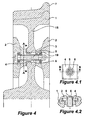
- the spring sleeve 4 comprises a combination of a cylindrical centering sleeve 4a and a generally rectangular spring plate 4b.
- the centering sleeve 4a serves to locate in the bore 21 through the flange 15.
- the spring plate 4b engages with a suitably shaped recess in the brake disk 2.
- Opposite, generally radially oriented edges of the spring plate 4b are upturned to provide a resilient bias against relative movement between the disk and flange in the tangential direction.
- Other shapes for the spring plate may also be envisaged including trapezoidal or arc shaped plates corresponding to the geometry of the brake disk.
- the spring sleeve 4 may preferably be manufactured as a shrink fit component whereby the centering sleeve 4a is cooled before insertion into the hole in the pre-tempered spring plate 4b. On warming of the centering sleeve 4a, it expands to firmly attach the two elements together. Such a connection is preferred since any heating of the spring plate 4b e.g by welding could be detrimental to its spring characteristics.
- FIG. 4 A further alternative form of the spring element is disclosed in Figure 4 .
- This embodiment is substantially similar to the embodiment of Figure 3 but is formed as a single piece by stamping, machine pressing or similar methods prior to the heat treatment required to achieve the desired spring characteristics.
- FIGS. 3 and 4 show a single spring element mounted in the bore on one side of the flange. It is envisaged that the spring elements may be arranged in each of the bores alternately on the inside and outside surfaces of the wheel flange. It is however also possible that each bore is provided with two spring elements 4, each inserted from a respective side of the flange.
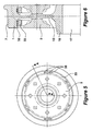
- Figures 5 and 6 show an alternative embodiment of a vibration absorbing device for a wheel set of a rail vehicle.
- a rail wheel 1 includes a rim 7, a hub 18 and a flange 15 extending between the rim 7 and the hub 18.
- Brake disks 2 are mounted on the flange 15 of the wheel 1 according to standard practice.
- the brake disks 2 play no role in the absorbing of vibrations (although they are an integral part of the inertial mass of the wheel set) and could take any appropriate form or be omitted completely. This arrangement is particularly advantageous in those constructions where axle mounted braking means are employed.
- annular ring 33 is provided adjacent the inner surface of the rim 7.
- the annular ring 33 is preferably made of a metal of high specific mass such as iron or lead in order to maximise its inertial mass about the axle 17. Other sufficiently massive alternatives including composites and alloys may also be considered.
- the annular ring is provided on its circumferentially outer surface with a resilient rubber layer 32. The rubber layer 32 is in turn connected to the inner surface of the rim 7 such that the annular ring 33 may oscillate with respect to the rim 7.
- Various means of attaching the rubber layer to the rim 7 and to the annular ring 33 may be used including vulcanisation, adhesives, welding or mechanical fixation means such as bolts or clips, all of which should ensure that the connection between rim 7 and annular ring 33 is subjected to the resilience of the rubber layer 32.
- Other methods of providing resilient support to the annular ring 33 may also be envisaged, including spring steel clips or shims which facilitate vibration of the annular ring 33 in the circumferential direction with respect to the wheel 1. These could be combined with additional means such as the prepared surface 3 of Figures 1 to 4 above to ensure the requisite damping.
- the rubber layer 32 or other resilient means should be selected in conjunction with the inertial mass of the annular ring to match the harmonic frequency of torsional vibrations in the wheel set.
- the rubber layer 32 according to this embodiment provides the dual functions of spring and damper. Such arrangements have been shown to provide effective vibration absorption over a wide range of frequencies.
- the annular ring 33 comprises a plurality of segments connected together by bolts 35. Such an arrangement provides for ease of mounting on existing wheel sets. Other connecting means such as pins or screws may be employed and the annular ring 33 may also be formed as a chain having one or more separable links.
- the wheel itself may be provided with a resilient mounting such that all or part of the wheel may rotate with respect to the axle.
- An arrangement whereby the outer rim of the wheel is mounted by resilient means to the remainder of the wheel by suitably calibrated resilient means such as an annular rubber rim is considered. This arrangement would have the advantage that the wheel rim has both considerable mass and is located at the point of maximum amplitude of vibration of the wheel set.
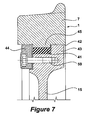
- Figure 7 discloses such an arrangement of a wheel 1 having a flange 15.
- the rim 7 is provided with an interior surface 42 having a ridge shaped annular protrusion 45. This is received by a correspondingly shaped region formed by a supporting element 43 at the outer periphery of the flange 15 and a locking ring 44 secured by bolt 50, whereby a tongue and groove type connection is formed.
- the parts could be reversed with the groove being formed in the inner surface 42 of the rim and the ridge formed on the supporting element 43.
- the wheel rim 7 is arranged to be resiliently mounted with respect to the remainder of the wheel.
- a rubber band or tyre 41 is provided between the inner surface 42 of the rim 7 and the supporting element 43.
- the tyre 41 is preferably attached to both the rim 7 and the supporting element 43 by adhesive, vulcanisation or the like.
- the joint may rely only on friction between the rubber and the adjacent surfaces to transfer forces from the wheel to the rim.
- the wheel set may be provided with a drive system and drive control which is better adapted to reduce wheel slip by avoidance of those control parameters relating to torsional vibration which would otherwise have been needed.
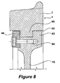
- Figure 9 shows an alternative arrangement of a resiliently mounted rim which does not require an additional locking ring.
- relative movement takes place between the adjacent surfaces of the rim 7 and the supporting element 43 and also a washer 51 provided on the securing bolt 50. Any or all of these surfaces may be suitably provided with friction determining or reducing means.
- elongate or oval bores 52 oriented in the circumferential direction, through which the securing bolts 50 insert.
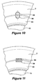
- Figure 10 shows an example of a spring element 53 arranged between the rim 7 and the supporting element 43. It comprises an oval sleeve of spring steel which is inserted into a correspondingly shaped oval recess 54 formed partially in the rim 7 and partially in the supporting element 43.
- the recess 54 is accessible and visible from the exterior surface of the wheel and a number of spring elements 53 and recesses 54 may be arranged around the circumference.
- spring elements may be arranged between the ridge and groove elements of Figure 8 , locked in place by the presence of the locking ring 44.
- Figure 11 shows an alternative arrangement using a helical spring 55 received in a correspondingly shaped cylindrical recess 54 formed between the rim 7 and the supporting element 43.
- Other forms of spring elements such as the split spring or the spring plates of Figures 2 to 4 or any other appropriate resilient means such as rubber or elastomeric blocks may equally be used to provide the necessary resilience.
- the present invention has been described in relation to wheel mounted vibration absorbing devices, it is noted that such arrangements may equally be mounted upon the axle itself.
- the brake disk is resiliently mounted to the axle by an appropriate spring damper system such that all or part of the mass of the brake disk functions to absorb torsional vibrations in the axle.
Landscapes
- Engineering & Computer Science (AREA)
- Mechanical Engineering (AREA)
- General Engineering & Computer Science (AREA)
- Physics & Mathematics (AREA)
- Acoustics & Sound (AREA)
- Aviation & Aerospace Engineering (AREA)
- Braking Arrangements (AREA)
- Vibration Prevention Devices (AREA)
- Automatic Cycles, And Cycles In General (AREA)
- Railway Tracks (AREA)
- Vehicle Body Suspensions (AREA)
- Platform Screen Doors And Railroad Systems (AREA)
- Machines For Laying And Maintaining Railways (AREA)
Claims (24)
- Radsatz für ein Schienenfahrzeug, umfassend ein Paar von Rädern (1), die durch eine Achse (17) miteinander verbunden sind, und eine Schwingungsabsorptionsvorrichtung, umfassend eine Masse, die für Schwingungsbewegungen in Bezug auf den Radsatz federnd montiert ist, und ein zwischen der Masse und dem Radsatz wirkendes Federelement (4, 53), dadurch gekennzeichnet, dass die Masse für Umfangsschwingungsbewegungen federnd angebracht ist, wobei das Federelement (4, 53) im Umfangsrichtung zwischen der Masse und dem Radsatz wirkt, so dass die Masse auf der Resonanzfrequenz von Drehschwingungen des Rad-Achse-Systems schwingen kann, und wobei das Dämpfen der Schwingungsbewegungen von einer reibungsbestimmenden Fläche zwischen einander berührenden Oberflächen des Radsatzes und der Masse bereitgestellt wird.
- Radsatz nach einem der vorhergehenden Ansprüche, bei dem die Schwingungsabsorptionsvorrichtung an dem Rad (1) montiert ist.
- Radsatz nach einem der vorhergehenden Ansprüche, bei dem die Masse der Schwingungsabsorptionsvorrichtung wenigstens ein Segment eines ringförmigen Rings (33) umfasst, der in Bezug auf die Achse (17) konzentrisch angebracht ist.
- Radsatz nach Anspruch 3, bei dem das Ringsegment über das Federelement (4, 53) am Rad montiert ist.
- Radsatz nach Anspruch 4, bei dem das Rad (1) mit einer Bohrung (21) versehen ist und das Federelement (4, 53) eine Zentrierhülse (4a) zum Einsetzen in die Bohrung (21) und eine Federscheibe (4b) zum Eingriff mit dem Ringsegment umfasst.
- Radsatz nach Anspruch 4, bei dem das Rad (1) mit einer Bohrung (21) versehen ist und das Ringsegment mit einer Gegenbohrung (20, 20') versehen ist und das Federelement (4, 53) eine Federhülse (4) umfasst, die in der Bohrung (21, 52) sowie in der Gegenbohrung (20, 20') steckt.
- Radsatz nach Anspruch 5, bei dem die Radhülse (4) einen Längsschlitz (25) aufweist, dessen Breite die maxiale Schwingungsweite des Ringsegments in Bezug auf das Rad (1) bestimmt.
- Radsatz nach einem der Ansprüche 3 bis 7, bei dem das Rad (1) einen Flansch (15) und ein Paar Ringsegmente umfasst, die an entgegengesetzten Seiten des Rades (1) angebracht sind und durch den Flansch (15) hindurch miteinander verbunden sind, um gemeinsam zu schwingen.
- Radsatz nach Anspruch 8, bei dem das Rad (1) mit einer Bohrung (21, 52) durch den Flansch (15) versehen ist und die Federhülse (4) durch die Bohrung (21, 52) verläuft und in Gegenbohrungen (20, 20') steckt, die in beiden Ringsegmenten ausgebildet sind.
- Radsatz nach Anspruch 9, bei dem die Ringsegmente mit einem durch die Federhülse (4) verlaufenden Befestigungselement miteinander verbunden sind.
- Radsatz nach Anspruch 10, bei dem das Befestigungselement eine Druckhülse (6) und eine Spannschraube umfasst, wobei die Druckhülse (6) eine Länge zur Abstützung zwischen den Ringsegmenten durch den Flansch (15) hindurch aufweist, wodurch beim Spannen die Vorspannung der Schraube (5) von der Druckhülse (6) aufgenommen werden kann, um die Kontaktkraft zwischen den Ringsegmenten und dem Flansch (15) zu reduzieren.
- Radsatz nach einem der Ansprüche 3 bis 11, bei dem das Ringsegment aus einer Bremsscheibe (2) besteht.
- Radsatz nach einem der Ansprüche 5 bis 11, bei dem das Ringsegment aus einer Bremsscheibe (2) besteht und die Bohrung (21, 52) und/oder die Gegenbohrung (20, 20') elliptisch oder oval und radial ausgerichtet ist, um thermische Ausdehnung der Bremsscheibe (2) zuzulassen.
- Radsatz nach einem der Ansprüche 3 bis 11, bei dem die Masse an den Umfang des Rads angrenzend am Rad (1) montiert ist.
- Radsatz nach einem der Ansprüche 1 und 2, bei dem die Schwingungsabsorptionsvorrichtung einen Teil des Rades umfasst.
- Radsatz nach Anspruch 15, bei dem die Masse der Schwingungsabsorptionsvorrichtung durch den Radkranz (7) gebildet wird, der in Bezug auf den Rest des Rades federnd montiert ist.
- Radsatz nach Anspruch 1, bei dem die Schwingungsabsorptionsvorrichtung auf der Achse (17) neben dem Rad (1) angebracht ist.
- Radsatz nach einem der vorhergehenden Ansprüche, bei dem eine Schwingungsabsorptionsvorrichtung an oder neben beiden Rädern angebracht ist.
- Radsatz nach einem der vorhergehenden Ansprüche, ferner umfassend einen zum Verursachen der Drehung der Achse (17) in Eingriff gebrachten Antrieb.
- Radsatz nach Anspruch 19, bei dem der Antrieb die Achse (17) an oder neben ihrem Mittelpunkt in Eingriff nimmt.
- Radsatz nach Anspruch 19 oder 20, ferner umfassend ein Steuersystem, wobei das Steuersystem die Aufgabe hat, im Betrieb Schlupf zwischen den Rädern und der Schiene zu registrieren und zu steuern.
- Schienenfahrzeug, umfassend wenigstens einen Radsatz nach einem der Ansprüche 1 bis 21.
- Verfahren zum Verhindern oder Verringern von Drehschwingungen in einem Radsatz eines Schienenfahrzeugs, der ein Paar von Rädern (1) umfasst, die durch eine Achse (17) miteinander verbunden sind, dadurch gekennzeichnet, dass das Verfahren das Ermitteln der Resonanzfrequenz von Drehschwingungen des Rad-Achse-Systems und das federnde Rotieren einer Masse an dem Radsatz mithilfe eines Federelements (4, 53) umfasst, das in Anfangsrichtung zwischen dem Radsatz und der Masse wirkt, und einer reibungsbestimmenden Fläche zwischen einander berührenden Oberflächen des Radsatzes und der Masse, wobei die Masse und ihre federnde Anbringung so gewählt werden, dass sie mit oder in der Nähe dieser Resonanzfrequenz schwingen.
- Verfahren nach Anspruch 23, bei dem die Masse gemäß einem der Ansprüche 1 bis 21 montiert ist.
Priority Applications (1)
| Application Number | Priority Date | Filing Date | Title |
|---|---|---|---|
| SI200331647T SI1551646T1 (sl) | 2002-07-17 | 2003-07-16 | Zmanjĺ anje torzijske vibracije v setih ĺ˝elezniĺ kih koles |
Applications Claiming Priority (3)
| Application Number | Priority Date | Filing Date | Title |
|---|---|---|---|
| GB0216624 | 2002-07-17 | ||
| GB0216624A GB2390885A (en) | 2002-07-17 | 2002-07-17 | Rail vehicle wheel set with torsional vibration damping |
| PCT/IB2003/003816 WO2004007217A2 (en) | 2002-07-17 | 2003-07-16 | Reduction of torsional vibration in rail vehicle wheel sets |
Publications (2)
| Publication Number | Publication Date |
|---|---|
| EP1551646A2 EP1551646A2 (de) | 2005-07-13 |
| EP1551646B1 true EP1551646B1 (de) | 2009-05-20 |
Family
ID=9940659
Family Applications (1)
| Application Number | Title | Priority Date | Filing Date |
|---|---|---|---|
| EP03764089A Expired - Lifetime EP1551646B1 (de) | 2002-07-17 | 2003-07-16 | Verringerung von drehschwingungen in radsätzen von schienenfahrzeugen |
Country Status (14)
| Country | Link |
|---|---|
| US (1) | US7625030B2 (de) |
| EP (1) | EP1551646B1 (de) |
| CN (1) | CN100411889C (de) |
| AT (1) | ATE431787T1 (de) |
| AU (1) | AU2003256002B2 (de) |
| CA (1) | CA2492534C (de) |
| DE (2) | DE20320277U1 (de) |
| DK (1) | DK1551646T3 (de) |
| ES (1) | ES2327226T3 (de) |
| GB (1) | GB2390885A (de) |
| PT (1) | PT1551646E (de) |
| SI (1) | SI1551646T1 (de) |
| WO (1) | WO2004007217A2 (de) |
| ZA (1) | ZA200500215B (de) |
Cited By (4)
| Publication number | Priority date | Publication date | Assignee | Title |
|---|---|---|---|---|
| EP2960073A1 (de) | 2014-06-26 | 2015-12-30 | Bombardier Transportation GmbH | Fahrgestelleinheit mit reduzierter Torsionsschwingung |
| EP2960544A1 (de) | 2014-06-26 | 2015-12-30 | Bombardier Transportation GmbH | Fahrgestelleinheit mit Verbindungsanordnung für reduzierte Torsionsschwingung |
| EP2960133A1 (de) | 2014-06-26 | 2015-12-30 | Bombardier Transportation GmbH | Fahrgestelleinheit mit verbesserter Bremsscheibenkupplung |
| EP4371846A1 (de) | 2022-11-17 | 2024-05-22 | ALSTOM Transportation Germany GmbH | Schwingungsdämpfende anordnung für ein schienenfahrzeug |
Families Citing this family (33)
| Publication number | Priority date | Publication date | Assignee | Title |
|---|---|---|---|---|
| EP2302250B1 (de) | 2006-05-01 | 2012-07-04 | American Precision Industries Inc. | Brems- oder Kupplungsvorrichtung |
| DE102008003923A1 (de) | 2008-01-11 | 2009-07-30 | Knorr-Bremse Systeme für Schienenfahrzeuge GmbH | Schienenrad |
| DE102008031419A1 (de) * | 2008-07-04 | 2010-01-14 | Muhr Und Bender Kg | Drehschwingungsdämpfer |
| JP5428505B2 (ja) * | 2009-04-30 | 2014-02-26 | サンスター技研株式会社 | フローティングブレーキディスクの組立方法 |
| US8661678B1 (en) * | 2010-02-16 | 2014-03-04 | Uremet Corporation | Combination roller coaster wheel |
| KR200470713Y1 (ko) * | 2010-11-10 | 2014-01-08 | 주식회사 에이브이티 | 방음 차륜 |
| DE102011100974A1 (de) * | 2011-05-09 | 2012-11-15 | Knorr-Bremse Systeme für Schienenfahrzeuge GmbH | Schienenrad und Verfahren zur Herstellung eines Schienenrades |
| DE102011102518A1 (de) | 2011-05-26 | 2012-11-29 | Knorr-Bremse Systeme für Schienenfahrzeuge GmbH | Radbremsscheiben |
| US8814276B2 (en) * | 2011-06-10 | 2014-08-26 | Goodrich Corporation | System and method for a wheel lock ring assembly |
| CN103216566B (zh) * | 2012-01-18 | 2015-02-11 | 北京自动化控制设备研究所 | 一种适应超音速飞行环境的惯导减振防冲参数设计方法 |
| RU2509017C1 (ru) * | 2012-07-30 | 2014-03-10 | Открытое акционерное общество Научно-исследовательский и конструкторско-технологический институт подвижного состава (ОАО "ВНИКТИ") | Дисковый тормоз ходового колеса |
| US9346318B2 (en) * | 2013-03-27 | 2016-05-24 | Goodrich Corporation | System and method for a wheel lock ring assembly |
| BR112015023937B1 (pt) * | 2013-03-28 | 2020-09-29 | Nippon Steel Corporation | Roda à prova de som para veículo ferroviário |
| AT514902A1 (de) * | 2013-09-24 | 2015-04-15 | Siemens Ag Oesterreich | Schienenrad mit Radbremsscheibe |
| CZ304953B6 (cs) * | 2013-10-17 | 2015-02-04 | Bonatrans Group A.S. | Tlumič vibrací a hluku |
| EP3106701A4 (de) * | 2014-02-14 | 2017-10-11 | Nippon Steel & Sumitomo Metal Corporation | Eisenbahnrad mit einer bremsscheibe |
| US10254155B2 (en) * | 2014-09-05 | 2019-04-09 | Abb Schweiz Ag | Monitoring torsional oscillations in a turbine-generator |
| DE102015212737A1 (de) * | 2015-07-08 | 2017-01-12 | Schaeffler Technologies AG & Co. KG | Fliehkraftpendeleinrichtung |
| CN104943468B (zh) * | 2015-07-13 | 2017-06-16 | 西南交通大学 | 列车降噪车轮 |
| WO2017099074A1 (ja) * | 2015-12-08 | 2017-06-15 | 東日本旅客鉄道株式会社 | 鉄道車両用ブレーキディスク |
| FR3048919B1 (fr) * | 2016-03-17 | 2019-06-28 | Mg-Valdunes | Roue de vehicule ferroviaire et procede de fabrication correspondant |
| DE102016117104A1 (de) * | 2016-09-12 | 2018-03-15 | Bochumer Verein Verkehrstechnik Gmbh | Mehrteiliges, gefedertes Schienenrad |
| FR3065439B1 (fr) * | 2017-04-24 | 2020-08-14 | Safran Landing Systems | Procede d’attenuation des vibrations des roues freinees d’aeronef |
| US11181167B2 (en) | 2017-04-24 | 2021-11-23 | Bridgestone Americas Tire Operations, Llc | Tuned mass-spring damper |
| CN110962501A (zh) * | 2018-09-29 | 2020-04-07 | 中车戚墅堰机车车辆工艺研究所有限公司 | 轨道车辆用弹性车轮、弹性车轮组件及轨道车辆 |
| CN112789427B (zh) * | 2018-10-03 | 2023-03-17 | 日本制铁株式会社 | 铁道车辆用的制动盘的安装结构、以及使用它的制动盘单元 |
| CN112460170A (zh) * | 2019-09-06 | 2021-03-09 | 常州中车铁马科技实业有限公司 | 轴装制动盘连接装置以及采用该装置的车辆 |
| KR20210054665A (ko) * | 2019-11-06 | 2021-05-14 | 현대자동차주식회사 | 자동차 휠의 흡진장치 |
| CN111577798A (zh) * | 2020-05-20 | 2020-08-25 | 中车株洲电力机车有限公司 | 一种制动盘及轨道车辆的车轮 |
| AU2021203541B2 (en) * | 2020-06-19 | 2023-03-16 | Westinghouse Air Brake Technologies Corporation | Brake assembly |
| JP7665385B2 (ja) * | 2021-04-02 | 2025-04-21 | ナブテスコ株式会社 | ブレーキディスク付き車輪およびブレーキディスク |
| SI26286A (sl) * | 2021-12-23 | 2023-06-30 | Kovis D.O.O. | Kolesni zavorni disk za tirna vozila z izboljšanim vpetjem |
| DE102022123566A1 (de) * | 2022-09-15 | 2024-03-21 | Knorr-Bremse Systeme für Nutzfahrzeuge GmbH | Scheibenbremse für ein Nutzfahrzeug |
Family Cites Families (23)
| Publication number | Priority date | Publication date | Assignee | Title |
|---|---|---|---|---|
| US1765477A (en) * | 1927-10-12 | 1930-06-24 | Eli O Ackerman | Vibration-dampening device |
| US2646308A (en) * | 1943-04-05 | 1953-07-21 | Pirelli | Resilient wheel for vehicles rolling on rails |
| US3530960A (en) * | 1968-03-15 | 1970-09-29 | Bergische Stahlindustrie | Wheel and brake construction |
| GB1528126A (en) * | 1974-12-20 | 1978-10-11 | Girling Ltd | Disc brakes |
| US3993356A (en) * | 1975-10-14 | 1976-11-23 | Caterpillar Tractor Co. | Track carrying wheels for crawler type vehicles having improved panel assemblies |
| DE2616393A1 (de) * | 1976-04-14 | 1977-11-03 | Deutsche Bundesbahn | Verfahren zur vermeidung von schienenriffeln und einrichtungen zur durchfuehrung der verfahren |
| GB1599434A (en) * | 1977-05-06 | 1981-10-07 | Krupp Ag Huettenwerke | Vibration absorbing track wheel |
| DE2816561C3 (de) * | 1978-04-17 | 1981-10-15 | Krupp Stahl Ag, 4630 Bochum | System aus Schienenrad und Gleis für Schienenfahrzeuge |
| DE2835020C2 (de) * | 1978-08-10 | 1983-10-20 | Krupp Stahl Ag, 4630 Bochum | Schwingungsdämpfer |
| DE2922585B1 (de) * | 1979-06-02 | 1980-12-11 | Krupp Ag Huettenwerke | Schwingungsabsorber fuer Resonanzschwingungen rotierender Koerper |
| DE3033246C2 (de) * | 1980-09-04 | 1983-02-03 | Krupp Stahl Ag, 4630 Bochum | Schwingungsgedämpftes Schienenrad |
| US4635990A (en) * | 1982-07-07 | 1987-01-13 | Voroshilovgradsky Mashinostroitelny Institut | Resilient wheel of a railway car |
| CA1219818A (en) * | 1984-03-12 | 1987-03-31 | Roy E. Smith | Brake disc design for wheel mounted discs |
| GB8821630D0 (en) * | 1988-09-02 | 1988-10-12 | Lucas Ind Plc | Improvements in disc assemblies for vehicle disc brakes |
| DE19501613A1 (de) | 1995-01-20 | 1996-07-25 | Vsg Verkehrstechnik Gmbh | Schwingungsgedämpftes Schienenrad |
| DE29604157U1 (de) * | 1996-03-06 | 1997-07-10 | Bergische Stahl-Industrie, 42859 Remscheid | Schienenrad, insbesondere gummigefedertes Schienenrad |
| DE19620902C2 (de) * | 1996-05-23 | 1998-05-07 | Vsg Verkehrstechnik Gmbh | Leichtscheibenrad mit einer beidseitig über große Bögen in Radnabe und Radkranz übergehenden Scheibe mit symmetrischem Aufbau |
| FR2750650B1 (fr) * | 1996-07-03 | 1998-11-06 | Valdunes | Procede d'insonorisation d'une roue de chemin de fer et roue de chemin de fer insonorisee |
| US6352294B1 (en) * | 1996-12-17 | 2002-03-05 | Tomoe Electric Manufacturing Co., Ltd. | Wheel for a track travel moving body, moving body provided with same, rail and travelling equipment using rail |
| NL1008966C2 (nl) * | 1998-04-22 | 1999-10-25 | Skf Eng & Res Centre Bv | Spoorwegvoertuigwiel met verbeterde dempingseigenschappen. |
| DE19856881B4 (de) | 1998-12-10 | 2005-10-13 | Daimlerchrysler Ag | Vorrichtung zur Verringerung oder Vermeidung von Reibschwingungen an Radsätzen von Schienenfahrzeugen |
| DE10160599A1 (de) * | 2000-12-11 | 2002-06-13 | Yokohama Rubber Co Ltd | Kraftfahrzeugrad und zugehörige Befestigungsanordnung |
| CN1317141C (zh) * | 2002-03-01 | 2007-05-23 | 刘起清 | 除震车轮 |
-
2002
- 2002-07-17 GB GB0216624A patent/GB2390885A/en not_active Withdrawn
-
2003
- 2003-07-16 DE DE20320277U patent/DE20320277U1/de not_active Expired - Lifetime
- 2003-07-16 PT PT03764089T patent/PT1551646E/pt unknown
- 2003-07-16 AT AT03764089T patent/ATE431787T1/de active
- 2003-07-16 DE DE60327703T patent/DE60327703D1/de not_active Expired - Lifetime
- 2003-07-16 WO PCT/IB2003/003816 patent/WO2004007217A2/en not_active Ceased
- 2003-07-16 DK DK03764089T patent/DK1551646T3/da active
- 2003-07-16 EP EP03764089A patent/EP1551646B1/de not_active Expired - Lifetime
- 2003-07-16 CN CNB038167379A patent/CN100411889C/zh not_active Expired - Fee Related
- 2003-07-16 US US10/521,361 patent/US7625030B2/en not_active Expired - Fee Related
- 2003-07-16 AU AU2003256002A patent/AU2003256002B2/en not_active Ceased
- 2003-07-16 CA CA2492534A patent/CA2492534C/en not_active Expired - Fee Related
- 2003-07-16 SI SI200331647T patent/SI1551646T1/sl unknown
- 2003-07-16 ES ES03764089T patent/ES2327226T3/es not_active Expired - Lifetime
-
2005
- 2005-01-10 ZA ZA200500215A patent/ZA200500215B/xx unknown
Cited By (4)
| Publication number | Priority date | Publication date | Assignee | Title |
|---|---|---|---|---|
| EP2960073A1 (de) | 2014-06-26 | 2015-12-30 | Bombardier Transportation GmbH | Fahrgestelleinheit mit reduzierter Torsionsschwingung |
| EP2960544A1 (de) | 2014-06-26 | 2015-12-30 | Bombardier Transportation GmbH | Fahrgestelleinheit mit Verbindungsanordnung für reduzierte Torsionsschwingung |
| EP2960133A1 (de) | 2014-06-26 | 2015-12-30 | Bombardier Transportation GmbH | Fahrgestelleinheit mit verbesserter Bremsscheibenkupplung |
| EP4371846A1 (de) | 2022-11-17 | 2024-05-22 | ALSTOM Transportation Germany GmbH | Schwingungsdämpfende anordnung für ein schienenfahrzeug |
Also Published As
| Publication number | Publication date |
|---|---|
| AU2003256002B2 (en) | 2010-04-22 |
| CA2492534A1 (en) | 2004-01-22 |
| ATE431787T1 (de) | 2009-06-15 |
| WO2004007217A3 (en) | 2004-06-03 |
| CA2492534C (en) | 2011-07-12 |
| EP1551646A2 (de) | 2005-07-13 |
| GB0216624D0 (en) | 2002-08-28 |
| PT1551646E (pt) | 2009-08-03 |
| GB2390885A (en) | 2004-01-21 |
| ES2327226T3 (es) | 2009-10-27 |
| US20060021542A1 (en) | 2006-02-02 |
| CN100411889C (zh) | 2008-08-20 |
| WO2004007217A8 (en) | 2005-07-21 |
| DE20320277U1 (de) | 2004-10-21 |
| AU2003256002A1 (en) | 2004-02-02 |
| WO2004007217A2 (en) | 2004-01-22 |
| CN1668481A (zh) | 2005-09-14 |
| ZA200500215B (en) | 2006-02-22 |
| DK1551646T3 (da) | 2009-08-31 |
| US7625030B2 (en) | 2009-12-01 |
| DE60327703D1 (de) | 2009-07-02 |
| SI1551646T1 (sl) | 2009-10-31 |
Similar Documents
| Publication | Publication Date | Title |
|---|---|---|
| EP1551646B1 (de) | Verringerung von drehschwingungen in radsätzen von schienenfahrzeugen | |
| US4355578A (en) | Railway wheels and rails damping structures | |
| EP0987470B1 (de) | Zahnkettentriebwerk mit innerem Torsionsdämpfer | |
| US20030037999A1 (en) | Vibration inhibiting structure for rotor | |
| JP4094986B2 (ja) | 均一なトルク伝達分配を適切に促進するブレーキローター取り付けアセンブリ | |
| US4496183A (en) | Vibration-damped wheel for rail vehicles | |
| EP3090192B1 (de) | Schwingungs- und schalldämpfer | |
| JPS64390Y2 (de) | ||
| US6655508B2 (en) | Disc brake rotor | |
| JP4293901B2 (ja) | ディスクブレーキ用のブレーキシュー | |
| WO2008028830A1 (en) | Passive dynamic vibration absorber | |
| EP1071565A1 (de) | Schienenfahrzeugrad mit dämpfungseigenschaften | |
| US5836427A (en) | Mounting construction of disc brake assembly | |
| US6336533B1 (en) | Noise dampening brake shoe | |
| US6488324B1 (en) | Railway vehicle wheel with improved damping characteristics | |
| CN219809322U (zh) | 用于旋转体的共振振动的振动吸收器和具有振动吸收器的轨道车轮 | |
| JPS6369445A (ja) | 車両駆動装置 | |
| JP2003320932A (ja) | キー付ブッシュ及び鉄道用車輪並びに輪軸 | |
| JP4235929B2 (ja) | 車両駆動装置 | |
| SU1659232A1 (ru) | Упругое колесо рельсового транспортного средства | |
| JP2003014008A (ja) | ディスクブレーキ装置 | |
| JP2003104001A (ja) | 弾性ホイール | |
| KR19980011138U (ko) | 자동차 구동축용질량형 댐퍼 | |
| JP2002067605A (ja) | 自動車用ホイールの組付け構造 |
Legal Events
| Date | Code | Title | Description |
|---|---|---|---|
| PUAI | Public reference made under article 153(3) epc to a published international application that has entered the european phase |
Free format text: ORIGINAL CODE: 0009012 |
|
| 17P | Request for examination filed |
Effective date: 20050214 |
|
| AK | Designated contracting states |
Kind code of ref document: A2 Designated state(s): AT BE BG CH CY CZ DE DK EE ES FI FR GB GR HU IE IT LI LU MC NL PT RO SE SI SK TR |
|
| 17Q | First examination report despatched |
Effective date: 20070810 |
|
| GRAP | Despatch of communication of intention to grant a patent |
Free format text: ORIGINAL CODE: EPIDOSNIGR1 |
|
| GRAS | Grant fee paid |
Free format text: ORIGINAL CODE: EPIDOSNIGR3 |
|
| GRAA | (expected) grant |
Free format text: ORIGINAL CODE: 0009210 |
|
| RAP1 | Party data changed (applicant data changed or rights of an application transferred) |
Owner name: BOMBARDIER TRANSPORTATION GMBH |
|
| AK | Designated contracting states |
Kind code of ref document: B1 Designated state(s): AT BE BG CH CY CZ DE DK EE ES FI FR GB GR HU IE IT LI LU MC NL PT RO SE SI SK TR |
|
| REG | Reference to a national code |
Ref country code: GB Ref legal event code: FG4D |
|
| REG | Reference to a national code |
Ref country code: CH Ref legal event code: EP |
|
| REG | Reference to a national code |
Ref country code: IE Ref legal event code: FG4D |
|
| REF | Corresponds to: |
Ref document number: 60327703 Country of ref document: DE Date of ref document: 20090702 Kind code of ref document: P |
|
| REG | Reference to a national code |
Ref country code: CH Ref legal event code: NV Representative=s name: ABREMA AGENCE BREVET ET MARQUES, GANGUILLET |
|
| REG | Reference to a national code |
Ref country code: PT Ref legal event code: SC4A Free format text: AVAILABILITY OF NATIONAL TRANSLATION Effective date: 20090727 |
|
| REG | Reference to a national code |
Ref country code: RO Ref legal event code: EPE |
|
| REG | Reference to a national code |
Ref country code: DK Ref legal event code: T3 |
|
| REG | Reference to a national code |
Ref country code: SE Ref legal event code: TRGR |
|
| REG | Reference to a national code |
Ref country code: GR Ref legal event code: EP Ref document number: 20090401994 Country of ref document: GR |
|
| REG | Reference to a national code |
Ref country code: ES Ref legal event code: FG2A Ref document number: 2327226 Country of ref document: ES Kind code of ref document: T3 |
|
| REG | Reference to a national code |
Ref country code: HU Ref legal event code: AG4A Ref document number: E006202 Country of ref document: HU |
|
| PG25 | Lapsed in a contracting state [announced via postgrant information from national office to epo] |
Ref country code: EE Free format text: LAPSE BECAUSE OF FAILURE TO SUBMIT A TRANSLATION OF THE DESCRIPTION OR TO PAY THE FEE WITHIN THE PRESCRIBED TIME-LIMIT Effective date: 20090520 |
|
| PG25 | Lapsed in a contracting state [announced via postgrant information from national office to epo] |
Ref country code: MC Free format text: LAPSE BECAUSE OF NON-PAYMENT OF DUE FEES Effective date: 20090731 |
|
| PLBE | No opposition filed within time limit |
Free format text: ORIGINAL CODE: 0009261 |
|
| STAA | Information on the status of an ep patent application or granted ep patent |
Free format text: STATUS: NO OPPOSITION FILED WITHIN TIME LIMIT |
|
| 26N | No opposition filed |
Effective date: 20100223 |
|
| PG25 | Lapsed in a contracting state [announced via postgrant information from national office to epo] |
Ref country code: IE Free format text: LAPSE BECAUSE OF NON-PAYMENT OF DUE FEES Effective date: 20090716 |
|
| PG25 | Lapsed in a contracting state [announced via postgrant information from national office to epo] |
Ref country code: CY Free format text: LAPSE BECAUSE OF FAILURE TO SUBMIT A TRANSLATION OF THE DESCRIPTION OR TO PAY THE FEE WITHIN THE PRESCRIBED TIME-LIMIT Effective date: 20090520 |
|
| REG | Reference to a national code |
Ref country code: FR Ref legal event code: PLFP Year of fee payment: 13 |
|
| PGFP | Annual fee paid to national office [announced via postgrant information from national office to epo] |
Ref country code: LU Payment date: 20150731 Year of fee payment: 13 |
|
| PGFP | Annual fee paid to national office [announced via postgrant information from national office to epo] |
Ref country code: NL Payment date: 20150730 Year of fee payment: 13 |
|
| PGFP | Annual fee paid to national office [announced via postgrant information from national office to epo] |
Ref country code: GB Payment date: 20150730 Year of fee payment: 13 Ref country code: FI Payment date: 20150729 Year of fee payment: 13 Ref country code: DE Payment date: 20150730 Year of fee payment: 13 Ref country code: DK Payment date: 20150730 Year of fee payment: 13 Ref country code: CH Payment date: 20150819 Year of fee payment: 13 Ref country code: BG Payment date: 20150730 Year of fee payment: 13 Ref country code: ES Payment date: 20150813 Year of fee payment: 13 |
|
| PGFP | Annual fee paid to national office [announced via postgrant information from national office to epo] |
Ref country code: HU Payment date: 20150819 Year of fee payment: 13 Ref country code: GR Payment date: 20150730 Year of fee payment: 13 Ref country code: AT Payment date: 20150731 Year of fee payment: 13 Ref country code: FR Payment date: 20150730 Year of fee payment: 13 Ref country code: SE Payment date: 20150730 Year of fee payment: 13 Ref country code: BE Payment date: 20150730 Year of fee payment: 13 |
|
| PGFP | Annual fee paid to national office [announced via postgrant information from national office to epo] |
Ref country code: IT Payment date: 20150730 Year of fee payment: 13 |
|
| PGFP | Annual fee paid to national office [announced via postgrant information from national office to epo] |
Ref country code: RO Payment date: 20160628 Year of fee payment: 14 Ref country code: TR Payment date: 20160622 Year of fee payment: 14 |
|
| PGFP | Annual fee paid to national office [announced via postgrant information from national office to epo] |
Ref country code: SK Payment date: 20160715 Year of fee payment: 14 Ref country code: PT Payment date: 20160715 Year of fee payment: 14 Ref country code: CZ Payment date: 20160714 Year of fee payment: 14 Ref country code: SI Payment date: 20160627 Year of fee payment: 14 |
|
| PG25 | Lapsed in a contracting state [announced via postgrant information from national office to epo] |
Ref country code: BE Free format text: LAPSE BECAUSE OF NON-PAYMENT OF DUE FEES Effective date: 20160731 |
|
| REG | Reference to a national code |
Ref country code: DE Ref legal event code: R119 Ref document number: 60327703 Country of ref document: DE |
|
| REG | Reference to a national code |
Ref country code: DK Ref legal event code: EBP Effective date: 20170131 |
|
| REG | Reference to a national code |
Ref country code: CH Ref legal event code: PL |
|
| REG | Reference to a national code |
Ref country code: NL Ref legal event code: MM Effective date: 20160801 |
|
| REG | Reference to a national code |
Ref country code: SE Ref legal event code: EUG |
|
| REG | Reference to a national code |
Ref country code: AT Ref legal event code: MM01 Ref document number: 431787 Country of ref document: AT Kind code of ref document: T Effective date: 20160716 |
|
| GBPC | Gb: european patent ceased through non-payment of renewal fee |
Effective date: 20160716 |
|
| REG | Reference to a national code |
Ref country code: GR Ref legal event code: ML Ref document number: 20090401994 Country of ref document: GR Effective date: 20170207 |
|
| PG25 | Lapsed in a contracting state [announced via postgrant information from national office to epo] |
Ref country code: FI Free format text: LAPSE BECAUSE OF NON-PAYMENT OF DUE FEES Effective date: 20160716 Ref country code: HU Free format text: LAPSE BECAUSE OF NON-PAYMENT OF DUE FEES Effective date: 20160717 Ref country code: NL Free format text: LAPSE BECAUSE OF NON-PAYMENT OF DUE FEES Effective date: 20160801 Ref country code: FR Free format text: LAPSE BECAUSE OF NON-PAYMENT OF DUE FEES Effective date: 20160801 Ref country code: GR Free format text: LAPSE BECAUSE OF NON-PAYMENT OF DUE FEES Effective date: 20170207 Ref country code: SE Free format text: LAPSE BECAUSE OF NON-PAYMENT OF DUE FEES Effective date: 20160717 Ref country code: DE Free format text: LAPSE BECAUSE OF NON-PAYMENT OF DUE FEES Effective date: 20170201 Ref country code: CH Free format text: LAPSE BECAUSE OF NON-PAYMENT OF DUE FEES Effective date: 20160731 Ref country code: LI Free format text: LAPSE BECAUSE OF NON-PAYMENT OF DUE FEES Effective date: 20160731 |
|
| REG | Reference to a national code |
Ref country code: FR Ref legal event code: ST Effective date: 20170331 |
|
| PG25 | Lapsed in a contracting state [announced via postgrant information from national office to epo] |
Ref country code: AT Free format text: LAPSE BECAUSE OF NON-PAYMENT OF DUE FEES Effective date: 20160716 Ref country code: GB Free format text: LAPSE BECAUSE OF NON-PAYMENT OF DUE FEES Effective date: 20160716 Ref country code: BG Free format text: LAPSE BECAUSE OF NON-PAYMENT OF DUE FEES Effective date: 20170228 |
|
| PG25 | Lapsed in a contracting state [announced via postgrant information from national office to epo] |
Ref country code: IT Free format text: LAPSE BECAUSE OF NON-PAYMENT OF DUE FEES Effective date: 20160716 Ref country code: LU Free format text: LAPSE BECAUSE OF NON-PAYMENT OF DUE FEES Effective date: 20160716 |
|
| PG25 | Lapsed in a contracting state [announced via postgrant information from national office to epo] |
Ref country code: DK Free format text: LAPSE BECAUSE OF NON-PAYMENT OF DUE FEES Effective date: 20160731 |
|
| REG | Reference to a national code |
Ref country code: SK Ref legal event code: MM4A Ref document number: E 5885 Country of ref document: SK Effective date: 20170716 |
|
| PG25 | Lapsed in a contracting state [announced via postgrant information from national office to epo] |
Ref country code: RO Free format text: LAPSE BECAUSE OF NON-PAYMENT OF DUE FEES Effective date: 20170716 Ref country code: CZ Free format text: LAPSE BECAUSE OF NON-PAYMENT OF DUE FEES Effective date: 20170716 |
|
| REG | Reference to a national code |
Ref country code: SI Ref legal event code: KO00 Effective date: 20180320 |
|
| PG25 | Lapsed in a contracting state [announced via postgrant information from national office to epo] |
Ref country code: SK Free format text: LAPSE BECAUSE OF NON-PAYMENT OF DUE FEES Effective date: 20170716 Ref country code: SI Free format text: LAPSE BECAUSE OF NON-PAYMENT OF DUE FEES Effective date: 20170717 Ref country code: PT Free format text: LAPSE BECAUSE OF NON-PAYMENT OF DUE FEES Effective date: 20180116 Ref country code: ES Free format text: LAPSE BECAUSE OF NON-PAYMENT OF DUE FEES Effective date: 20160717 |
|
| REG | Reference to a national code |
Ref country code: ES Ref legal event code: FD2A Effective date: 20181129 |
|
| PG25 | Lapsed in a contracting state [announced via postgrant information from national office to epo] |
Ref country code: TR Free format text: LAPSE BECAUSE OF NON-PAYMENT OF DUE FEES Effective date: 20170716 |