EP1551657B1 - Appareil et procede de fixation d'un joint sur un assemblage de fenetre encastre - Google Patents
Appareil et procede de fixation d'un joint sur un assemblage de fenetre encastre Download PDFInfo
- Publication number
- EP1551657B1 EP1551657B1 EP03771642A EP03771642A EP1551657B1 EP 1551657 B1 EP1551657 B1 EP 1551657B1 EP 03771642 A EP03771642 A EP 03771642A EP 03771642 A EP03771642 A EP 03771642A EP 1551657 B1 EP1551657 B1 EP 1551657B1
- Authority
- EP
- European Patent Office
- Prior art keywords
- gasket
- seal
- fixture
- work piece
- retention slot
- Prior art date
- Legal status (The legal status is an assumption and is not a legal conclusion. Google has not performed a legal analysis and makes no representation as to the accuracy of the status listed.)
- Expired - Lifetime
Links
Images

Classifications
-
- B—PERFORMING OPERATIONS; TRANSPORTING
- B60—VEHICLES IN GENERAL
- B60J—WINDOWS, WINDSCREENS, NON-FIXED ROOFS, DOORS, OR SIMILAR DEVICES FOR VEHICLES; REMOVABLE EXTERNAL PROTECTIVE COVERINGS SPECIALLY ADAPTED FOR VEHICLES
- B60J10/00—Sealing arrangements
- B60J10/45—Assembling sealing arrangements with vehicle parts
-
- Y—GENERAL TAGGING OF NEW TECHNOLOGICAL DEVELOPMENTS; GENERAL TAGGING OF CROSS-SECTIONAL TECHNOLOGIES SPANNING OVER SEVERAL SECTIONS OF THE IPC; TECHNICAL SUBJECTS COVERED BY FORMER USPC CROSS-REFERENCE ART COLLECTIONS [XRACs] AND DIGESTS
- Y10—TECHNICAL SUBJECTS COVERED BY FORMER USPC
- Y10T—TECHNICAL SUBJECTS COVERED BY FORMER US CLASSIFICATION
- Y10T29/00—Metal working
- Y10T29/49—Method of mechanical manufacture
- Y10T29/49826—Assembling or joining
-
- Y—GENERAL TAGGING OF NEW TECHNOLOGICAL DEVELOPMENTS; GENERAL TAGGING OF CROSS-SECTIONAL TECHNOLOGIES SPANNING OVER SEVERAL SECTIONS OF THE IPC; TECHNICAL SUBJECTS COVERED BY FORMER USPC CROSS-REFERENCE ART COLLECTIONS [XRACs] AND DIGESTS
- Y10—TECHNICAL SUBJECTS COVERED BY FORMER USPC
- Y10T—TECHNICAL SUBJECTS COVERED BY FORMER US CLASSIFICATION
- Y10T29/00—Metal working
- Y10T29/49—Method of mechanical manufacture
- Y10T29/49826—Assembling or joining
- Y10T29/49863—Assembling or joining with prestressing of part
-
- Y—GENERAL TAGGING OF NEW TECHNOLOGICAL DEVELOPMENTS; GENERAL TAGGING OF CROSS-SECTIONAL TECHNOLOGIES SPANNING OVER SEVERAL SECTIONS OF THE IPC; TECHNICAL SUBJECTS COVERED BY FORMER USPC CROSS-REFERENCE ART COLLECTIONS [XRACs] AND DIGESTS
- Y10—TECHNICAL SUBJECTS COVERED BY FORMER USPC
- Y10T—TECHNICAL SUBJECTS COVERED BY FORMER US CLASSIFICATION
- Y10T29/00—Metal working
- Y10T29/49—Method of mechanical manufacture
- Y10T29/49826—Assembling or joining
- Y10T29/49863—Assembling or joining with prestressing of part
- Y10T29/4987—Elastic joining of parts
-
- Y—GENERAL TAGGING OF NEW TECHNOLOGICAL DEVELOPMENTS; GENERAL TAGGING OF CROSS-SECTIONAL TECHNOLOGIES SPANNING OVER SEVERAL SECTIONS OF THE IPC; TECHNICAL SUBJECTS COVERED BY FORMER USPC CROSS-REFERENCE ART COLLECTIONS [XRACs] AND DIGESTS
- Y10—TECHNICAL SUBJECTS COVERED BY FORMER USPC
- Y10T—TECHNICAL SUBJECTS COVERED BY FORMER US CLASSIFICATION
- Y10T29/00—Metal working
- Y10T29/49—Method of mechanical manufacture
- Y10T29/49826—Assembling or joining
- Y10T29/49863—Assembling or joining with prestressing of part
- Y10T29/4987—Elastic joining of parts
- Y10T29/49872—Confining elastic part in socket
-
- Y—GENERAL TAGGING OF NEW TECHNOLOGICAL DEVELOPMENTS; GENERAL TAGGING OF CROSS-SECTIONAL TECHNOLOGIES SPANNING OVER SEVERAL SECTIONS OF THE IPC; TECHNICAL SUBJECTS COVERED BY FORMER USPC CROSS-REFERENCE ART COLLECTIONS [XRACs] AND DIGESTS
- Y10—TECHNICAL SUBJECTS COVERED BY FORMER USPC
- Y10T—TECHNICAL SUBJECTS COVERED BY FORMER US CLASSIFICATION
- Y10T29/00—Metal working
- Y10T29/53—Means to assemble or disassemble
- Y10T29/53039—Means to assemble or disassemble with control means energized in response to activator stimulated by condition sensor
- Y10T29/53061—Responsive to work or work-related machine element
- Y10T29/53074—Responsive to work or work-related machine element with means to fasten by elastic joining
-
- Y—GENERAL TAGGING OF NEW TECHNOLOGICAL DEVELOPMENTS; GENERAL TAGGING OF CROSS-SECTIONAL TECHNOLOGIES SPANNING OVER SEVERAL SECTIONS OF THE IPC; TECHNICAL SUBJECTS COVERED BY FORMER USPC CROSS-REFERENCE ART COLLECTIONS [XRACs] AND DIGESTS
- Y10—TECHNICAL SUBJECTS COVERED BY FORMER USPC
- Y10T—TECHNICAL SUBJECTS COVERED BY FORMER US CLASSIFICATION
- Y10T29/00—Metal working
- Y10T29/53—Means to assemble or disassemble
- Y10T29/53657—Means to assemble or disassemble to apply or remove a resilient article [e.g., tube, sleeve, etc.]
-
- Y—GENERAL TAGGING OF NEW TECHNOLOGICAL DEVELOPMENTS; GENERAL TAGGING OF CROSS-SECTIONAL TECHNOLOGIES SPANNING OVER SEVERAL SECTIONS OF THE IPC; TECHNICAL SUBJECTS COVERED BY FORMER USPC CROSS-REFERENCE ART COLLECTIONS [XRACs] AND DIGESTS
- Y10—TECHNICAL SUBJECTS COVERED BY FORMER USPC
- Y10T—TECHNICAL SUBJECTS COVERED BY FORMER US CLASSIFICATION
- Y10T29/00—Metal working
- Y10T29/53—Means to assemble or disassemble
- Y10T29/53683—Spreading parts apart or separating them from face to face engagement
-
- Y—GENERAL TAGGING OF NEW TECHNOLOGICAL DEVELOPMENTS; GENERAL TAGGING OF CROSS-SECTIONAL TECHNOLOGIES SPANNING OVER SEVERAL SECTIONS OF THE IPC; TECHNICAL SUBJECTS COVERED BY FORMER USPC CROSS-REFERENCE ART COLLECTIONS [XRACs] AND DIGESTS
- Y10—TECHNICAL SUBJECTS COVERED BY FORMER USPC
- Y10T—TECHNICAL SUBJECTS COVERED BY FORMER US CLASSIFICATION
- Y10T29/00—Metal working
- Y10T29/53—Means to assemble or disassemble
- Y10T29/53796—Puller or pusher means, contained force multiplying operator
- Y10T29/53839—Puller or pusher means, contained force multiplying operator having percussion or explosive operator
- Y10T29/53843—Tube, sleeve, or ferrule inserting or removing
Definitions
- the present invention generally relates to a seal attachment fixture and, more particularly, to a seal attachment fixture for an encapsulated window assembly. Most particularly, the present invention relates to a seal attachment fixture for attaching a seal to an automotive window with an encapsulated gasket. A method for operating such a seal attachment apparatus is also disclosed.
- Encapsulated window assemblies are well known in the art, where a first side of the gasket has been disposed onto at least a portion of the periphery of the window.
- the encapsulated window assembly may also include a means to: 1) mount the window assembly to a vehicle, 2) to minimize chipping and breaking of the window, and 3) to reduce noise, wind, and moisture from entering the vehicle.
- the encapsulated window assembly should be aesthetically pleasing.
- the gasket is composed of plastic/rubber
- the gasket material is typically relatively rigid and not flexible enough to allow a second side of the gasket to completely prevent noise, wind, and moisture from entering the vehicle. For this reason it is common to provide additional means to more reliably seal out these environmental elements.
- One means that is used is to attach a more flexible plastic/rubber seal to the second side of the gasket.
- the attachment of the seal to the gasket has been accomplished by using a gasket that has a female feature and/or retention slot defined along the second side, wherein the retention slot has lips covering the retention slot opening.
- a male portion of the seal is disposed within the gasket by manually spreading the lips apart at the opening of the gasket retention slot so as to allow entry of a male portion of the seal.
- the lips of the gasket are released, which results in the seal being firmly seated.
- GB-A-1517917 which teaches a tool with a seal foot that is wider than a groove opening in a receiving gasket, thus the seal foot is disposed into the groove while spreading open the groove opening, The tool is then moved continuously within the groove, with the seal being continuously inserted within the groove, However, the seal insertion must be accomplished quickly before the groove opening relaxes too much and consequently blocks insertion of the seal into the groove opening:
- fixture for attaching a seal within a gasket which comprises the features of claim 1
- a method of attaching a seal to a gasket which comprises the features of claim 6.
- the present invention relates to a seal attachment fixture that is used for attaching a flexible seal to a relatively rigid gasket, the gasket having openable lip portions on a second side of the gasket, opposite a first side of the gasket that is disposed upon a work piece.
- the gasket may extend around at least a portion of the work piece.
- the work piece is preferably an encapsulated automotive window assembly.
- the fixture comprises at least one fixture member and at least one locating stop for holding a work piece.
- the work piece includes at least a portion of a gasket having lip portions that define a retention slot therebetween. When the fixture member is moved into contact with the gasket, the fixture member urges the lip portions to open, thus exposing the retention slot for seal insertion.
- a method of attaching the seal to the gasket where the gasket is disposed on the work piece that is positioned on the seal attachment fixture, the work piece having openable lip portions that define the retention slot therebetween.
- the method comprises: 1) urging the separate fixture member into contact with the openable lip portions of the gasket, wherein the fixture members cause the lips of the gasket to open, and thereby to expose the retention slot defined within the gasket, 2) inserting a portion of the flexible seal into the gasket by inserting a male portion of the seal between the open lip portions of the gasket, 3) moving the fixture members out of contact with the gasket, thus allowing the lips of the gasket to close over the male portion of the flexible seal, and 4) removing the work piece with attached seal from the fixture.
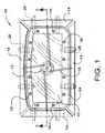
- the present invention involves a seal attachment fixture 10 as shown in Fig. 1 , where a work piece 22, for example, an automotive window with encapsulated gasket 24, is positioned within the seal attachment fixture 10.
- the seal attachment fixture 10 comprises a plate 26 (shown in Fig. 2 ), a drive 42 that is attached to the plate 26, a rotating hub mechanism 12, which is rotatably attached to the drive 42, and having at least two arms 18, but preferably four arms 18. A first end of each arm 18 is pivotably attached to the rotating hub mechanism 12, while a second end of each arm 18 is pivotably attached to separate fixture members 14 that are slidably attached to at least two rails 28.
- the seal attachment fixture 10 also comprises at least one locating stops 16, but preferably a minimum of three (see Fig. 1 ), which are attached to the plate 26 and possibly adjustably attached to the plate 26.
- the rotating hub mechanism 12 is rotated by the drive 42, for example, a pneumatic cylinder, an electric motor, a hydraulic mechanism, or other rotating means that are known in the art, in a first direction to extend the arms 18.
- the extension of the arms 18 provides clearance between the fixture members 14 and the work piece, so that the work piece 22 can be positioned on the locating stops 16.
- the locating stops 16, which are positioned between the slidable fixture members 14 and inside of the gasket, are aligned with openable gasket lip portions 34 (refer to Fig. 3 ). With the arms 18 extended, as so described, the lips 34 are not in contact with the fixture members 14.
- the rotating hub mechanism 12 is rotated by the drive 42 in a second direction so that the arms 18 are retracted, which causes the fixture members 14 to come into contact with the lips 34. This results in the fixture members 14 spreading the lips 34 open and exposing a retention slot 32.
- the retention slot 32 is preferably defined within the gasket 24 on a side opposite a side of the gasket 24 that is disposed on the work piece 22.
- a male portion 36 of a seal 20, as shown in Fig. 5 is inserted between the lips 34 and within the retention slot 32 (shown in Fig. 3 ) throughout the gasket 24. Insertion of the seal 20 may be by any appropriate method, for example, manually or robotically.
- the rotating hub mechanism 10 When the complete male portion 36 has been inserted into the retention slot 32 around at least a portion of the periphery of the gasket 24, the rotating hub mechanism 10 is rotated in the first direction so as to extend the arms 18. This rotation causes the arms 18 to slide the fixture members 14 out of contact with the lips 34, which close over the male portion 36 of the seal 20.
- the work piece 22 is removed from the locating stops 16 with the seal male portion 36 attached to the gasket 24, while a seal exterior portion 38 is exposed outside of the gasket 24. This exterior portion 38 is then available for creating sealable contact between the work piece 22 and an automotive vehicle window aperture (not shown).
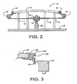
- Fig. 2 illustrates a cross-sectional view of the seal attachment fixture of Fig. 1 , taken along the 2-2 line of Fig. 1 , however, with the arms 18 retracted. Therein are shown the fixture members 14 causing the lips 34 to be spread apart and exposing the gasket retention slot 32.
- Fig. 3 shows an exploded cutaway cross-sectional view of the work piece 22 with the lips 34 spread apart and the retention slot 32 exposed. It should be noted that the present invention may be practiced as shown where the fixture member 14 is pointed at the point of contact with the lips 34, but may also be non-pointed (not shown) and still be within the scope of the invention.
- Fig. 4 illustrates an exploded cutaway cross-sectional view of an edge of an assembled work piece 22 with the seal 20 disposed within the gasket retention slot 32.
- Shown in Fig. 5 is a cross-sectional view of the seal 20 with the male portion 36 and the exterior portion 38.
- the encapsulated gasket 24 may be composed of any suitable thermoplastic or thermoset material.
- the seal 20 may be composed of any suitable extrudable plastic material.
- a method of attaching the flexible seal 20 to the rigid gasket 24 is provided where the gasket 24 is disposed on the work piece 22, for example, an encapsulated window assembly, that is positioned on the seal attachment fixture 10, the gasket 24 having openable lip portions 34 that define the retention slot 32 therebetween.
- the method comprises: 1) urging the separate fixture members 14 into contact with the openable lip portions 34 of the gasket 24, wherein the fixture members 14 clause the lips 34 of the gasket 24 to open, and thereby to expose the retention slot 32 defined within the gasket 24, 2) inserting a portion of the flexible seal 20 into the gasket 24 by inserting a male portion of the seal 36 between the open lip portions 34 of the gasket 24, 3) moving the fixture members 14 out of contact with the gasket 24, thus allowing the lips 34 of the gasket 24 to close over the male portion 36 of the flexible seal 20, and 4) removing the work piece 22 with attached seal 20 from the fixture 10.
Landscapes
- Engineering & Computer Science (AREA)
- Mechanical Engineering (AREA)
- Seal Device For Vehicle (AREA)
- Automobile Manufacture Line, Endless Track Vehicle, Trailer (AREA)
Claims (17)
- Dispositif de fixation (10) pour fixer un joint (20) à l'intérieur d'une garniture (24), comprenant :au moins un élément de fixation (14) ;au moins un arrêt de positionnement (16) retenant une pièce (22) qui comprend au moins une portion d'une garniture (24) ayant des portions de lèvres ouvrables (34) qui définissent une fente de retenue (32) entre elles ; etune commande (42) pour déplacer l'élément de fixation (14) ;caractérisé par un mécanisme à moyeu rotatif (12) fixé à rotation à la commande (42), le mécanisme à moyeu rotatif ayant au moins deux bras (18), une première extrémité de chaque bras (18) étant fixée à pivotement au mécanisme à moyeu rotatif (12) et une seconde extrémité de chaque bras (18) étant fixée à pivotement à des éléments de fixation séparés (14) ;dans lequel les éléments de fixation (14) sont alignés avec des portions de lèvres séparées (34) qui sont disposées d'un côté de la garniture (24) opposé à l'endroit où la garniture (24) est disposée sur la pièce (22), chaque élément de fixation (14) étant fixé à coulissement à au moins deux rails (28) ; etdans lequel le déplacement de l'élément de fixation (14) en contact avec la garniture extérieure à la fente de retenue (32) pousse les portions de lèvres (34) à s'ouvrir, exposant ainsi la fente de retenue (32) pour l'insertion du joint (20).
- Dispositif de fixation de joint étanche (10) selon la revendication 1, dans lequel le joint(20) est flexible et la garniture (24) est relativement rigide.
- Dispositif de fixation de joint étanche (10) selon la revendication 2, comprenant en outre une plaque (26), à laquelle sont fixés la commande (42) et les arrêts de positionnement (16).
- Dispositif de fixation de joint étanche (10) selon la revendication 3, dans lequel les arrêts de positionnement (16) sont fixés de manière ajustable à la plaque (26).
- Dispositif de fixation de joint étanche (10) selon la revendication 4, dans lequel la garniture (24) est enchâssée sur la périphérie de la pièce (22), laquelle pièce (22) est un vitrage d'automobile.
- Procédé de fixation d'un joint (20) sur une garniture (24) avec le dispositif de fixation de joint (10) selon la revendication 1, caractérisé par les étapes suivantes:mettre en oeuvre une pièce (22) dont la garniture (24) est fixée à au moins une de ses portions;presser un élément de fixation (14) en contact avec une portion de lèvre ouvrable (34) pour ouvrir les lèvres, le contact étant extérieur à la portion de fente de retenue (32) ;insérer une portion du joint (20) entre les portions de lèvres ouvrables (34); etpresser l'élément de fixation (14) hors contact avec la garniture (24), fixant ainsi le joint(20) à la pièce (22).
- Procédé selon la revendication 6, comprenant en outre l'étape consistant à :placer initialement la pièce (22), sur laquelle la garniture (24) a été fixée, sur des arrêts de positionnement (16).
- Procédé selon la revendication 7, dans lequel la pression de l'élément de fixation (14) comprend la rotation d'un mécanisme à moyeu (12).
- Procédé selon la revendication 8, dans lequel la rotation du mécanisme à moyeu (12) comprend le déplacement d'une commande (42).
- Procédé selon la revendication 9, dans lequel la rotation du mécanisme à moyeu (12) comprend l'alignement de l'élément de fixation (14) et des portions de lèvres séparées (34).
- Procédé selon la revendication 10, dans lequel la pression de l'élément de fixation (14) comprend le coulissement de l'élément de fixation (14) sur des rails (28).
- Procédé selon la revendication 11, comprenant en outre l'ajustement des arrêts de positionnement.
- Procédé selon la revendication 12, dans lequel l'insertion de l'élément de fixation (14) comprend un robot.
- Procédé selon la revendication 13, comprenant en outre le retrait de la pièce (22) des arrêts de positionnement (16).
- Procédé selon la revendication 6, comprenant en outre la à pression d'une pluralité d'éléments de fixation (14) en contact avec des portions de lèvres correspondantes (34) pour ouvrir les lèvres (34).
- Procédé selon la revendication 6, dans lequel la pièce (22) comprend une vitre de véhicule.
- Procédé selon la revendication 6, dans lequel le joint(20) est inséré à l'intérieur de la fente de retenue de garniture (32) à travers la garniture.
Applications Claiming Priority (5)
| Application Number | Priority Date | Filing Date | Title |
|---|---|---|---|
| US39845402P | 2002-07-25 | 2002-07-25 | |
| US398454P | 2002-07-25 | ||
| US10/442,470 US6874218B2 (en) | 2002-07-25 | 2003-05-21 | Apparatus and method for attaching a seal to an encapsulated window assembly |
| US442470 | 2003-05-21 | ||
| PCT/US2003/022325 WO2004011294A1 (fr) | 2002-07-25 | 2003-07-17 | Appareil et procede de fixation d'un joint sur un assemblage de fenetre encastre |
Publications (2)
| Publication Number | Publication Date |
|---|---|
| EP1551657A1 EP1551657A1 (fr) | 2005-07-13 |
| EP1551657B1 true EP1551657B1 (fr) | 2011-08-31 |
Family
ID=30773087
Family Applications (1)
| Application Number | Title | Priority Date | Filing Date |
|---|---|---|---|
| EP03771642A Expired - Lifetime EP1551657B1 (fr) | 2002-07-25 | 2003-07-17 | Appareil et procede de fixation d'un joint sur un assemblage de fenetre encastre |
Country Status (5)
| Country | Link |
|---|---|
| US (2) | US6874218B2 (fr) |
| EP (1) | EP1551657B1 (fr) |
| AT (1) | ATE522387T1 (fr) |
| AU (1) | AU2003251981A1 (fr) |
| WO (1) | WO2004011294A1 (fr) |
Families Citing this family (17)
| Publication number | Priority date | Publication date | Assignee | Title |
|---|---|---|---|---|
| US6649175B1 (en) * | 1998-05-04 | 2003-11-18 | Schering-Plough Healthcare Products, Inc. | Skin barrier composition |
| US6651402B2 (en) * | 2000-06-05 | 2003-11-25 | Kenneth D. Grunst | Methods and structures for sealing air gaps in a building |
| US6874218B2 (en) * | 2002-07-25 | 2005-04-05 | Pilkington North America, Inc. | Apparatus and method for attaching a seal to an encapsulated window assembly |
| US7891497B2 (en) * | 2006-09-29 | 2011-02-22 | M-I L.L.C. | Peripheral sealing system for pre-tensioned screens |
| DE202007007683U1 (de) * | 2007-05-30 | 2007-09-20 | Trw Automotive Electronics & Components Gmbh & Co. Kg | Werkzeug |
| US8322005B2 (en) * | 2008-10-23 | 2012-12-04 | Pow Specialty Equipment Inc. | Weather strip installation device |
| US9580954B2 (en) * | 2009-10-05 | 2017-02-28 | R Value, Inc. | Press fit storm window system |
| US10202796B2 (en) | 2009-10-05 | 2019-02-12 | R Value, Inc. | Press fit storm window system |
| US9255438B2 (en) | 2009-10-05 | 2016-02-09 | R Value, Inc. | Press fit storm window system |
| US8236570B2 (en) * | 2009-11-03 | 2012-08-07 | Infoscitex | Methods for identifying nucleic acid ligands |
| CN103052519A (zh) * | 2010-07-22 | 2013-04-17 | 万国卡车知识产权有限公司 | 挡风玻璃包封压条和固定挡风玻璃的方法 |
| US8832918B2 (en) | 2010-10-29 | 2014-09-16 | Toyota Motor Engineering & Manufacturing North America, Inc. | Frame device with shimming elements for installing a glass plane |
| US9180565B2 (en) | 2011-03-24 | 2015-11-10 | Pilkington Group Limited | Decorative trim assembly fixture and method of using same |
| USD715411S1 (en) * | 2011-11-18 | 2014-10-14 | Kansei Kogyo Co., Ltd. | Gasket for mounting on vehicle to provide seal with hood or trunk lid |
| US9120369B2 (en) * | 2011-12-19 | 2015-09-01 | Fca Us Llc | Glass run installation tool |
| EP3243994B1 (fr) * | 2016-05-09 | 2019-01-30 | R Value, Inc. | Système de contre-fenêtre à ajustement par pression |
| CN113333959B (zh) * | 2021-06-11 | 2022-12-13 | 包头江馨微电机科技有限公司 | 一种双轨道式vcm马达线圈漆包层激光去皮自动机 |
Family Cites Families (28)
| Publication number | Priority date | Publication date | Assignee | Title |
|---|---|---|---|---|
| US2189138A (en) * | 1938-06-03 | 1940-02-06 | Yellow Truck & Coach Mfg Co | Rubber mounting |
| US2464375A (en) * | 1945-09-04 | 1949-03-15 | Herbert H Twining | Holder for watch movements |
| US2647289A (en) * | 1950-08-24 | 1953-08-04 | Kaiser Frazer Corp | Window weatherstripping |
| US3363303A (en) * | 1965-08-26 | 1968-01-16 | P O Box 18992 | Weatherstrip mounting hand tool |
| US3488828A (en) * | 1967-11-30 | 1970-01-13 | Ppg Industries Inc | Means and method for inserting a structural gasket locking strip |
| US3550242A (en) * | 1968-03-11 | 1970-12-29 | Standard Products Co | Lock strip inserting tool |
| US3691596A (en) * | 1971-01-13 | 1972-09-19 | Judson T Ulansey | Fabric clip |
| GB1447491A (en) | 1972-10-16 | 1976-08-25 | Marler Haley Exposystems Ltd | Method of and apparatus for covering a substrate with a flexible material |
| GB1517917A (en) | 1974-10-04 | 1978-07-19 | Dixon Int Ltd | Manufacture of draught excluders |
| US4092394A (en) * | 1975-11-05 | 1978-05-30 | Dixon International Limited | Manufacture of draught excluders |
| NL7801875A (nl) * | 1977-02-24 | 1978-08-28 | Yoshida Kogyo Kk | Inrichting voor het aanbrengen van een pakking. |
| GB1597492A (en) * | 1977-03-11 | 1981-09-09 | Draftex Dev Ag | Windows |
| US4185371A (en) * | 1978-01-12 | 1980-01-29 | Barnett Melvin L | Beading installation tool |
| GB2153421B (en) * | 1984-01-27 | 1987-08-12 | Draftex Ind Ltd | Sealing strip |
| DE3410193A1 (de) | 1984-03-20 | 1985-09-26 | Metzeler Kautschuk GmbH, 8000 München | Vorrichtung zum abdichten des fensterschachtes eines kraftfahrzeuges |
| DE3506009A1 (de) * | 1985-02-21 | 1986-08-28 | Rockwell Golde Gmbh, 6000 Frankfurt | Starrer deckel fuer ein fahrzeugdach |
| US4620354A (en) * | 1985-05-28 | 1986-11-04 | General Motors Corporation | Method of applying weatherstrip to a vehicle body opening |
| US4768764A (en) * | 1986-05-12 | 1988-09-06 | Cole John R | Green tire holder |
| US4716641A (en) * | 1986-06-19 | 1988-01-05 | Shrimpton Ronald J | Truck windshield moulding insertion tool |
| US4897913A (en) * | 1986-07-18 | 1990-02-06 | General Motors Corporation | Method of using a robot for installing weather stripping in a door or like opening |
| GB2203474B (en) * | 1987-04-07 | 1990-10-17 | Autoroofs Ltd | Vehicle sunroofs |
| GB8827860D0 (en) * | 1988-02-10 | 1988-12-29 | Draftex Ind Ltd | Apparatus for fitting sealing & trimming strips |
| US5031293A (en) * | 1989-09-06 | 1991-07-16 | Draftex Industries Limited | Apparatus for fitting a flexible strip |
| US5010689A (en) * | 1990-03-19 | 1991-04-30 | The Standard Products Company | Glass run channel |
| US5462292A (en) * | 1992-11-30 | 1995-10-31 | Nishikawa Rubber Co., Ltd. | Door seal device |
| DE19923725C1 (de) | 1999-05-22 | 2000-07-20 | Webasto Vehicle Sys Int Gmbh | Deckel eines Fahrzeugdachs sowie Verfahren zur Herstellung eines solchen Deckels |
| ITMI20010202A1 (it) * | 2001-02-02 | 2002-08-02 | Ilpea Ind Spa | Metodo ed apparecchiatura per montare in modo automatizzato un profilo di tenuta ad una controporta per frigoriferi |
| US6874218B2 (en) * | 2002-07-25 | 2005-04-05 | Pilkington North America, Inc. | Apparatus and method for attaching a seal to an encapsulated window assembly |
-
2003
- 2003-05-21 US US10/442,470 patent/US6874218B2/en not_active Expired - Lifetime
- 2003-07-17 AT AT03771642T patent/ATE522387T1/de not_active IP Right Cessation
- 2003-07-17 AU AU2003251981A patent/AU2003251981A1/en not_active Abandoned
- 2003-07-17 EP EP03771642A patent/EP1551657B1/fr not_active Expired - Lifetime
- 2003-07-17 WO PCT/US2003/022325 patent/WO2004011294A1/fr not_active Ceased
-
2005
- 2005-01-26 US US11/043,767 patent/US20050132564A1/en not_active Abandoned
Also Published As
| Publication number | Publication date |
|---|---|
| US6874218B2 (en) | 2005-04-05 |
| EP1551657A1 (fr) | 2005-07-13 |
| ATE522387T1 (de) | 2011-09-15 |
| WO2004011294A1 (fr) | 2004-02-05 |
| US20050132564A1 (en) | 2005-06-23 |
| US20040016099A1 (en) | 2004-01-29 |
| AU2003251981A1 (en) | 2004-02-16 |
| WO2004011294B1 (fr) | 2004-03-25 |
Similar Documents
| Publication | Publication Date | Title |
|---|---|---|
| US6874218B2 (en) | Apparatus and method for attaching a seal to an encapsulated window assembly | |
| CA2338081C (fr) | Ensemble moule decoratif pour cadre de porte de vehicule | |
| US5449544A (en) | Weather strip for an automobile and a method for assembling the same | |
| US4839958A (en) | Method of using a robot for installing weather stripping in a door or like opening | |
| CA1338213C (fr) | Lisieres a calfeutrer | |
| US4970836A (en) | Access opening closure device | |
| DE69703241D1 (de) | Fensterschachtdichtungsprofil | |
| US4396326A (en) | Self sealing J nut | |
| KR20150089046A (ko) | 접착제-배킹 웨더스트립을 도포하기 위한 방법 및 장치 | |
| CN100436199C (zh) | 用于安装压条的系统和方法 | |
| CA2050149A1 (fr) | Moulure a bord chanfreine pour rainure de vitre | |
| US5467557A (en) | Window construction and method of making the same | |
| US4897913A (en) | Method of using a robot for installing weather stripping in a door or like opening | |
| EP1361098A1 (fr) | Méthode pour l'adhésion d'un joint à un vitrage | |
| US4719736A (en) | Removable window assembly | |
| JP3180493B2 (ja) | 自動車用ウエザストリップ及びその組付方法 | |
| US5826934A (en) | Cam-actuated vehicle sunroof, and method of installing the same | |
| EP1572483B1 (fr) | Procede et appareil permettant de fixer des bandes d'etancheite et de montage sur des elements | |
| US20160263968A1 (en) | Adjustable door glass attachment bracket | |
| JP3746866B2 (ja) | ドアインナーウェザーストリップ | |
| GB2512073A (en) | Fixing assembly for a watershield | |
| US4912827A (en) | Method for replacing a door panel | |
| FR2668569A1 (fr) | Dispositif de joint d'etancheite, notamment pour porte de vehicule, et procede de fabrication d'un tel dispositif. | |
| EP0228780A2 (fr) | Manchon composite | |
| EP1361097A1 (fr) | Méthode pour l'adhésion d'un joint à un vitrage |
Legal Events
| Date | Code | Title | Description |
|---|---|---|---|
| PUAI | Public reference made under article 153(3) epc to a published international application that has entered the european phase |
Free format text: ORIGINAL CODE: 0009012 |
|
| 17P | Request for examination filed |
Effective date: 20050110 |
|
| AK | Designated contracting states |
Kind code of ref document: A1 Designated state(s): AT BE BG CH CY CZ DE DK EE ES FI FR GB GR HU IE IT LI LU MC NL PT RO SE SI SK TR |
|
| 17Q | First examination report despatched |
Effective date: 20090717 |
|
| GRAP | Despatch of communication of intention to grant a patent |
Free format text: ORIGINAL CODE: EPIDOSNIGR1 |
|
| GRAS | Grant fee paid |
Free format text: ORIGINAL CODE: EPIDOSNIGR3 |
|
| GRAA | (expected) grant |
Free format text: ORIGINAL CODE: 0009210 |
|
| AK | Designated contracting states |
Kind code of ref document: B1 Designated state(s): AT BE BG CH CY CZ DE DK EE ES FI FR GB GR HU IE IT LI LU MC NL PT RO SE SI SK TR |
|
| REG | Reference to a national code |
Ref country code: CH Ref legal event code: EP Ref country code: GB Ref legal event code: FG4D |
|
| REG | Reference to a national code |
Ref country code: IE Ref legal event code: FG4D |
|
| REG | Reference to a national code |
Ref country code: DE Ref legal event code: R096 Ref document number: 60338289 Country of ref document: DE Effective date: 20111110 |
|
| REG | Reference to a national code |
Ref country code: NL Ref legal event code: VDEP Effective date: 20110831 |
|
| PG25 | Lapsed in a contracting state [announced via postgrant information from national office to epo] |
Ref country code: FI Free format text: LAPSE BECAUSE OF FAILURE TO SUBMIT A TRANSLATION OF THE DESCRIPTION OR TO PAY THE FEE WITHIN THE PRESCRIBED TIME-LIMIT Effective date: 20110831 Ref country code: NL Free format text: LAPSE BECAUSE OF FAILURE TO SUBMIT A TRANSLATION OF THE DESCRIPTION OR TO PAY THE FEE WITHIN THE PRESCRIBED TIME-LIMIT Effective date: 20110831 Ref country code: SE Free format text: LAPSE BECAUSE OF FAILURE TO SUBMIT A TRANSLATION OF THE DESCRIPTION OR TO PAY THE FEE WITHIN THE PRESCRIBED TIME-LIMIT Effective date: 20110831 |
|
| REG | Reference to a national code |
Ref country code: AT Ref legal event code: MK05 Ref document number: 522387 Country of ref document: AT Kind code of ref document: T Effective date: 20110831 |
|
| PG25 | Lapsed in a contracting state [announced via postgrant information from national office to epo] |
Ref country code: CY Free format text: LAPSE BECAUSE OF FAILURE TO SUBMIT A TRANSLATION OF THE DESCRIPTION OR TO PAY THE FEE WITHIN THE PRESCRIBED TIME-LIMIT Effective date: 20110831 Ref country code: SI Free format text: LAPSE BECAUSE OF FAILURE TO SUBMIT A TRANSLATION OF THE DESCRIPTION OR TO PAY THE FEE WITHIN THE PRESCRIBED TIME-LIMIT Effective date: 20110831 Ref country code: GR Free format text: LAPSE BECAUSE OF FAILURE TO SUBMIT A TRANSLATION OF THE DESCRIPTION OR TO PAY THE FEE WITHIN THE PRESCRIBED TIME-LIMIT Effective date: 20111201 Ref country code: AT Free format text: LAPSE BECAUSE OF FAILURE TO SUBMIT A TRANSLATION OF THE DESCRIPTION OR TO PAY THE FEE WITHIN THE PRESCRIBED TIME-LIMIT Effective date: 20110831 |
|
| PG25 | Lapsed in a contracting state [announced via postgrant information from national office to epo] |
Ref country code: BE Free format text: LAPSE BECAUSE OF FAILURE TO SUBMIT A TRANSLATION OF THE DESCRIPTION OR TO PAY THE FEE WITHIN THE PRESCRIBED TIME-LIMIT Effective date: 20110831 |
|
| PG25 | Lapsed in a contracting state [announced via postgrant information from national office to epo] |
Ref country code: SK Free format text: LAPSE BECAUSE OF FAILURE TO SUBMIT A TRANSLATION OF THE DESCRIPTION OR TO PAY THE FEE WITHIN THE PRESCRIBED TIME-LIMIT Effective date: 20110831 Ref country code: CZ Free format text: LAPSE BECAUSE OF FAILURE TO SUBMIT A TRANSLATION OF THE DESCRIPTION OR TO PAY THE FEE WITHIN THE PRESCRIBED TIME-LIMIT Effective date: 20110831 |
|
| PG25 | Lapsed in a contracting state [announced via postgrant information from national office to epo] |
Ref country code: RO Free format text: LAPSE BECAUSE OF FAILURE TO SUBMIT A TRANSLATION OF THE DESCRIPTION OR TO PAY THE FEE WITHIN THE PRESCRIBED TIME-LIMIT Effective date: 20110831 Ref country code: EE Free format text: LAPSE BECAUSE OF FAILURE TO SUBMIT A TRANSLATION OF THE DESCRIPTION OR TO PAY THE FEE WITHIN THE PRESCRIBED TIME-LIMIT Effective date: 20110831 Ref country code: PT Free format text: LAPSE BECAUSE OF FAILURE TO SUBMIT A TRANSLATION OF THE DESCRIPTION OR TO PAY THE FEE WITHIN THE PRESCRIBED TIME-LIMIT Effective date: 20120102 |
|
| PG25 | Lapsed in a contracting state [announced via postgrant information from national office to epo] |
Ref country code: DK Free format text: LAPSE BECAUSE OF FAILURE TO SUBMIT A TRANSLATION OF THE DESCRIPTION OR TO PAY THE FEE WITHIN THE PRESCRIBED TIME-LIMIT Effective date: 20110831 |
|
| PLBE | No opposition filed within time limit |
Free format text: ORIGINAL CODE: 0009261 |
|
| STAA | Information on the status of an ep patent application or granted ep patent |
Free format text: STATUS: NO OPPOSITION FILED WITHIN TIME LIMIT |
|
| 26N | No opposition filed |
Effective date: 20120601 |
|
| REG | Reference to a national code |
Ref country code: DE Ref legal event code: R097 Ref document number: 60338289 Country of ref document: DE Effective date: 20120601 |
|
| PGFP | Annual fee paid to national office [announced via postgrant information from national office to epo] |
Ref country code: GB Payment date: 20120725 Year of fee payment: 10 |
|
| PGFP | Annual fee paid to national office [announced via postgrant information from national office to epo] |
Ref country code: IT Payment date: 20120723 Year of fee payment: 10 Ref country code: DE Payment date: 20120727 Year of fee payment: 10 Ref country code: FR Payment date: 20120731 Year of fee payment: 10 |
|
| PG25 | Lapsed in a contracting state [announced via postgrant information from national office to epo] |
Ref country code: MC Free format text: LAPSE BECAUSE OF NON-PAYMENT OF DUE FEES Effective date: 20120731 |
|
| REG | Reference to a national code |
Ref country code: CH Ref legal event code: PL |
|
| PG25 | Lapsed in a contracting state [announced via postgrant information from national office to epo] |
Ref country code: ES Free format text: LAPSE BECAUSE OF FAILURE TO SUBMIT A TRANSLATION OF THE DESCRIPTION OR TO PAY THE FEE WITHIN THE PRESCRIBED TIME-LIMIT Effective date: 20111211 Ref country code: LI Free format text: LAPSE BECAUSE OF NON-PAYMENT OF DUE FEES Effective date: 20120731 Ref country code: CH Free format text: LAPSE BECAUSE OF NON-PAYMENT OF DUE FEES Effective date: 20120731 |
|
| REG | Reference to a national code |
Ref country code: IE Ref legal event code: MM4A |
|
| PG25 | Lapsed in a contracting state [announced via postgrant information from national office to epo] |
Ref country code: BG Free format text: LAPSE BECAUSE OF FAILURE TO SUBMIT A TRANSLATION OF THE DESCRIPTION OR TO PAY THE FEE WITHIN THE PRESCRIBED TIME-LIMIT Effective date: 20111130 |
|
| PG25 | Lapsed in a contracting state [announced via postgrant information from national office to epo] |
Ref country code: IE Free format text: LAPSE BECAUSE OF NON-PAYMENT OF DUE FEES Effective date: 20120717 |
|
| GBPC | Gb: european patent ceased through non-payment of renewal fee |
Effective date: 20130717 |
|
| REG | Reference to a national code |
Ref country code: FR Ref legal event code: ST Effective date: 20140331 |
|
| PG25 | Lapsed in a contracting state [announced via postgrant information from national office to epo] |
Ref country code: GB Free format text: LAPSE BECAUSE OF NON-PAYMENT OF DUE FEES Effective date: 20130717 Ref country code: TR Free format text: LAPSE BECAUSE OF FAILURE TO SUBMIT A TRANSLATION OF THE DESCRIPTION OR TO PAY THE FEE WITHIN THE PRESCRIBED TIME-LIMIT Effective date: 20110831 Ref country code: DE Free format text: LAPSE BECAUSE OF NON-PAYMENT OF DUE FEES Effective date: 20140201 |
|
| REG | Reference to a national code |
Ref country code: DE Ref legal event code: R119 Ref document number: 60338289 Country of ref document: DE Effective date: 20140201 |
|
| PG25 | Lapsed in a contracting state [announced via postgrant information from national office to epo] |
Ref country code: LU Free format text: LAPSE BECAUSE OF NON-PAYMENT OF DUE FEES Effective date: 20120717 Ref country code: FR Free format text: LAPSE BECAUSE OF NON-PAYMENT OF DUE FEES Effective date: 20130731 Ref country code: IT Free format text: LAPSE BECAUSE OF NON-PAYMENT OF DUE FEES Effective date: 20130717 |
|
| PG25 | Lapsed in a contracting state [announced via postgrant information from national office to epo] |
Ref country code: HU Free format text: LAPSE BECAUSE OF FAILURE TO SUBMIT A TRANSLATION OF THE DESCRIPTION OR TO PAY THE FEE WITHIN THE PRESCRIBED TIME-LIMIT Effective date: 20030717 |