EP1552199B1 - Robinet de gaz avec une vanne de securite electromagnetique - Google Patents
Robinet de gaz avec une vanne de securite electromagnetique Download PDFInfo
- Publication number
- EP1552199B1 EP1552199B1 EP03748073A EP03748073A EP1552199B1 EP 1552199 B1 EP1552199 B1 EP 1552199B1 EP 03748073 A EP03748073 A EP 03748073A EP 03748073 A EP03748073 A EP 03748073A EP 1552199 B1 EP1552199 B1 EP 1552199B1
- Authority
- EP
- European Patent Office
- Prior art keywords
- armature
- gas cock
- gas
- magnet
- housing
- Prior art date
- Legal status (The legal status is an assumption and is not a legal conclusion. Google has not performed a legal analysis and makes no representation as to the accuracy of the status listed.)
- Expired - Lifetime
Links
- 229920003023 plastic Polymers 0.000 claims description 6
- 239000004033 plastic Substances 0.000 claims description 6
- 239000000463 material Substances 0.000 claims description 4
- 239000002184 metal Substances 0.000 claims description 3
- 238000010276 construction Methods 0.000 claims description 2
- 230000003321 amplification Effects 0.000 claims 1
- 238000003199 nucleic acid amplification method Methods 0.000 claims 1
- 230000003213 activating effect Effects 0.000 abstract 1
- 238000013016 damping Methods 0.000 description 5
- 238000005516 engineering process Methods 0.000 description 3
- 238000004519 manufacturing process Methods 0.000 description 3
- 230000035939 shock Effects 0.000 description 3
- 230000002093 peripheral effect Effects 0.000 description 2
- 240000001439 Opuntia Species 0.000 description 1
- 235000004727 Opuntia ficus indica Nutrition 0.000 description 1
- 230000006978 adaptation Effects 0.000 description 1
- 239000002775 capsule Substances 0.000 description 1
- 238000004891 communication Methods 0.000 description 1
- 239000012530 fluid Substances 0.000 description 1
- 238000012986 modification Methods 0.000 description 1
- 230000004048 modification Effects 0.000 description 1
- 238000012806 monitoring device Methods 0.000 description 1
- 238000012544 monitoring process Methods 0.000 description 1
- 229920001296 polysiloxane Polymers 0.000 description 1
- 230000001681 protective effect Effects 0.000 description 1
- 238000007789 sealing Methods 0.000 description 1
Images
Classifications
-
- F—MECHANICAL ENGINEERING; LIGHTING; HEATING; WEAPONS; BLASTING
- F23—COMBUSTION APPARATUS; COMBUSTION PROCESSES
- F23N—REGULATING OR CONTROLLING COMBUSTION
- F23N1/00—Regulating fuel supply
- F23N1/005—Regulating fuel supply using electrical or electromechanical means
-
- F—MECHANICAL ENGINEERING; LIGHTING; HEATING; WEAPONS; BLASTING
- F16—ENGINEERING ELEMENTS AND UNITS; GENERAL MEASURES FOR PRODUCING AND MAINTAINING EFFECTIVE FUNCTIONING OF MACHINES OR INSTALLATIONS; THERMAL INSULATION IN GENERAL
- F16K—VALVES; TAPS; COCKS; ACTUATING-FLOATS; DEVICES FOR VENTING OR AERATING
- F16K31/00—Actuating devices; Operating means; Releasing devices
- F16K31/02—Actuating devices; Operating means; Releasing devices electric; magnetic
- F16K31/06—Actuating devices; Operating means; Releasing devices electric; magnetic using a magnet, e.g. diaphragm valves, cutting off by means of a liquid
- F16K31/08—Actuating devices; Operating means; Releasing devices electric; magnetic using a magnet, e.g. diaphragm valves, cutting off by means of a liquid using a permanent magnet
- F16K31/082—Actuating devices; Operating means; Releasing devices electric; magnetic using a magnet, e.g. diaphragm valves, cutting off by means of a liquid using a permanent magnet using a electromagnet and a permanent magnet
Definitions
- the present invention relates to a gas tap with an electromagnetic safety valve.
- the magnet armature presses the valve closure element onto a valve seat provided in the gas tap.
- the armature is actuated.
- a magnetic insert is known in particular for monitoring devices on gas-fired devices.
- the magnet insert has an electric blade held on a support plate and an armature plate which is connected to a valve lifter.
- the valve stem is slidably mounted in a protective capsule enclosing the electromagnet and the armature plate.
- the closing member of a shut-off valve is mounted.
- Comparable magnetic inserts are also made EP 1 036 987 and from EP 1 063 474 known.
- An electromagnetic safety valve is off DE 39 39 537 known.
- the object of the present invention is to provide a gas cock with an electromagnetic safety valve whose life is extended.
- the object of the invention is achieved by a gas tap with the features of claim 1.
- the electromagnetic coil is arranged as a separate component outside the armature housing of the magnetic insert. Due to the external arrangement of the electromagnetic coil mechanical shock loads from the armature in the armature housing are no longer directly on the solenoid coil transfer. Such mechanical shock loads cause in known magnetic inserts with arranged inside the armature housing solenoid coils that crack after only about 40,000 switching cycles electrical connections of the electromagnetic coil. According to the invention, the number of switching cycles of the magnetic insert can be significantly increased.
- the electromagnetic coil can be easily disassembled on the magnetic insert and / or gas-tightly separated from the gas path in the gas tap.
- the electromagnetic coil is therefore easily replaceable as a wearing part, without gas sealing surfaces between the magnetic insert and the gas tap are affected.
- the electromagnetic coil is arranged outside the gas tap when the magnetic insert is inserted in the gas tap.
- the electromagnetic coil can be replaced without disassembling the magnetic insert from the gas tap.
- the magnet armature of the magnetic insert can be advantageously extended to outside the gas cock.
- the extended magnet armature can be guided more precisely in the armature housing and can be moved with less play and / or less friction. The wear on armature guide sections in the armature housing is thereby reduced.
- the armature housing may, in the manner of a two-point bearing, have at least two magnet armature guide sections axially spaced from one another for guiding the magnet armature. This further improves the precise and low-friction movement of the armature. It is particularly advantageous for a good positioning behavior of the magnet armature when the two guide sections are formed of different materials, in particular of metal and of plastic.
- the distance between the two guide sections is as large as possible.
- This can be realized according to the invention when a first armature-armature guide section of the armature housing is provided inside the gas tap, and a second magnet armature guide section of the armature housing is formed outside the gas tap.
- a stationary counter anchor can preferably be arranged in the armature housing.
- the counter-anchor also serves to limit a Ankerhubes.
- the armature housing is formed in two parts from a first armature housing section inserted in the gas tap and from a second armature housing section protruding from the gas tap.
- the second armature housing section is preferably gas-tight with the gas tap in conjunction.
- the first armature housing section of the magnetic insert arranged in the gas tap is of identical construction to corresponding housing sections of commercially available magnet inserts.
- the magnetic insert according to the invention can be used with already produced in series gas taps, without any subsequent adaptation of the gas taps is to make. All modifications of the magnetic insert according to the invention, however, are provided on the second armature housing section outside the gas tap.
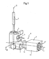
- FIG. 1 a conventional gas tap with a gas cock body 1 is shown.
- a tap axis 3 is rotatably mounted.
- a rotary knob is attached to the upper free end of the cock axis 3.
- a gas inlet 5 of the gas tap body 1 can be connected to a gas supply line, not shown.
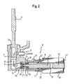
- the gas inlet 5 is connected via a gas path 6 shown in the following figures to a gas outlet 7 in fluid communication.
- a gas flow in the gas path 6 runs along the arrows shown in the figures.
- the Indian FIG. 1 shown gas tap has a safety valve 8 with a magnetic insert 9.
- the magnetic insert 9 is screwed by means of a union nut 11 to the gas cock body 1.
- a stop plug 13 is formed, which is rotatably mounted in a cone section of the gas cock body 1.
- the gas passage is adjusted by the gas path 6.
- This opens into a frontal mouth opening 14 of a horizontally extending receiving bore 15 of the gas tap.
- the gas path 6 continues through an opening in the cylindrical inner wall of the receiving bore 15 to the gas outlet 7.
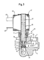
- the magnetic insert 9 has an armature housing 19, in which a magnet armature 21 is guided.
- the magnet armature 21 is a transfer ram 23 is formed.
- the armature housing 19 is made in two parts from a low-cost plastic housing part 37 and an armature guide sleeve 39 made of metal.
- the plastic housing part 37 is completely sunk in the receiving bore 15 of the gas cock body 1.
- An opposite to the sleeve-shaped guide portion 25 lying open end of the plastic housing part 37 is pushed onto an outer periphery of the armature guide sleeve 39.
- the plastic housing part 37 overlaps the armature guide sleeve 39 up to a peripheral flange 41 of the armature guide sleeve 39.
- the peripheral flange 41 of the armature guide sleeve 39 is gas-tight pressed by means of the screwed union nut 43 on an end-side outer edge of the receiving bore.
- the inner circumference of the armature guide sleeve 39 is in planar contact with the magnet armature 21.
- the inner circumference of the armature guide sleeve 39 therefore serves, as does the sleeve-shaped guide section 25, as a magnet armature guide section.
- An electromagnetic coil 45 is mounted on the outer circumference of the armature guide sleeve 39 arranged outside of the gas-cocked body 1.
- a locking disk 47 is pushed onto the armature guide sleeve 39 on the front side.
- the locking disk 47 is locked in a circumferential groove of the armature guide sleeve 39.
- the electromagnetic coil 39 has electrical connection contacts 49. These can be connected to an electrical flame monitoring element, ie a thermocouple, or to an electronic control device for fully automatic control of the safety valve 8. In the presence of a gas flame on a gas burner, the thermocouple generates an electrical voltage which is supplied via the electrical connection contacts 49 of the electromagnetic coil 45 and this excited.
- a magnetic force is exerted against the armature 21 against a spring force of the spring 33.
- the magnetic force brings the armature 21 in an open position in which the valve plate 29 is out of engagement with the valve seat 35. If the flame goes out during operation, the voltage and thus the magnetic force collapse. The armature 21 is therefore pressed by the spring force of the spring 33 again against the valve seat 35. When extinguished flame, therefore, the gas path 6 is closed in the gas.
- a counter-anchor 51 is stationary in the armature guide sleeve 39. The counter-anchor 51 also serves to limit an opening stroke of the armature 21st
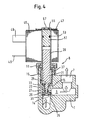
- a magnetic insert 9 according to the second embodiment is shown. Structure and operation of the magnetic insert 9 are identical to the magnetic insert 9 of the first embodiment with the exception that in the magnetic insert 9 from the FIG. 4
- a damping system for damping impact impacts of the armature 21 is provided on the counter-anchor 51.
- the damping system has on the one hand a recessed in the outer periphery of the counter-anchor 51 O-ring 53.
- the O-ring 53 is pressed between the inner circumference of the armature guide sleeve 39 and the counter-anchor 51 and allows a stationary support of the counter-armature 51.
- the armature housing 19 is closed gas-tight to the outside.
- a damping disk 55 made of silicone material is inserted between the upper end face of the armature guide sleeve 39 and the counter anchor 51 for damping the shocks exerted on the counter-armature 51.
- the upper end face of the armature guide sleeve 39 can - due to the gas-tight seal by the O-ring 53 - are formed with a manufacturing technology advantageous opening 57, as shown in the FIG. 4 is shown.
Landscapes
- Engineering & Computer Science (AREA)
- General Engineering & Computer Science (AREA)
- Mechanical Engineering (AREA)
- Physics & Mathematics (AREA)
- Electromagnetism (AREA)
- Chemical & Material Sciences (AREA)
- Combustion & Propulsion (AREA)
- Magnetically Actuated Valves (AREA)
Claims (12)
- Robinet de gaz comprenant une vanne de sécurité électromagnétique (8) destinée à obturer une voie de gaz (6) dans le robinet de gaz, laquelle vanne de sécurité (8) présente un insert magnétique (9) inséré dans le robinet de gaz et muni d'un boîtier d'induit (19), dans lequel est disposée une armature d'aimant mobile (21) munie d'un élément d'obturation de vanne (29) qui, pour fermer la voie du gaz (6), appuie sur un siège de vanne (35) ménagé dans le robinet de gaz, à laquelle armature d'aimant (21) correspond une bobine électromagnétique (45) qui, lorsqu'une tension est appliquée, actionne l'armature d'aimant (21), la bobine électromagnétique (45) étant disposée à l'extérieur du boîtier d'induit (19) de l'insert magnétique (9) en tant qu'un composant séparé.
- Robinet de gaz selon la revendication 1, caractérisé en ce que la bobine électromagnétique (45) est disposée de manière séparée de la voie du gaz (6) dans le robinet de gaz en étant étanche au gaz.
- Robinet de gaz selon la revendication 1 ou 2, caractérisé en ce que la bobine électromagnétique (45) est installée sur le boîtier d'induit (19) de l'insert magnétique (9) de manière facilement démontable.
- Robinet de gaz selon l'une quelconque des revendications précédentes, caractérisé en ce que la bobine électromagnétique (45) est disposée à l'extérieur du robinet de gaz.
- Robinet de gaz selon l'une quelconque des revendications précédentes, caractérisé en ce que l'armature d'aimant (21) de l'insert magnétique (9) dépasse jusqu'à l'extérieur du robinet de gaz.
- Robinet de gaz selon l'une quelconque des revendications précédentes, caractérisé en ce qu'au moins deux sections de guidage (25, 39) d'armature d'aimant, distancées axialement les unes des autres, destinées au guidage de l'armature d'aimant (21) sont réalisées dans le boîtier d'induit (19).
- Robinet de gaz selon la revendication 6, caractérisé en ce qu'une première section de guidage (25) d'armature d'aimant du boîtier d'induit (19) est réalisée à l'intérieur du robinet de gaz et en ce qu'une seconde section de guidage (39) d'armature d'aimant du boîtier d'induit (19) est réalisée à l'extérieur du robinet de gaz.
- Robinet de gaz selon la revendication 6 ou 7, caractérisé en ce que les au moins deux sections de guidage (25, 39) d'armature d'aimant sont réalisées dans des matières différentes, notamment en métal et en plastique.
- Robinet de gaz selon l'une quelconque des revendications précédentes, caractérisé en ce qu'un contre-induit (51) destiné à renforcer une force magnétique de l'insert magnétique (9) et/ou à limiter un trajet de course de l'induit est disposé dans le boîtier d'induit (19).
- Robinet de gaz selon l'une quelconque des revendications précédentes, caractérisé en ce que le boîtier d'induit (19) est réalisé en deux parties, à partir d'une première section (37) de boîtier d'induit insérée dans le robinet de gaz et d'une seconde section (39) de boîtier d'induit dépassant hors du robinet de gaz.
- Robinet de gaz selon la revendication 10, caractérisé en ce que la première section (37) de boîtier d'induit, insérée dans le robinet de gaz, de l'insert magnétique (9) est de construction identique à des sections de boîtier correspondantes d'inserts magnétiques du commerce.
- Robinet de gaz selon la revendication 10 ou 11, caractérisé en ce que la bobine électromagnétique (45), l'une des sections de guidage de l'armature d'aimant et/ou le contre-induit (51) sont ménagés sur la seconde section (39) de boîtier d'induit dépassant hors du robinet de gaz.
Priority Applications (1)
| Application Number | Priority Date | Filing Date | Title |
|---|---|---|---|
| EP03748073A EP1552199B1 (fr) | 2002-09-25 | 2003-09-22 | Robinet de gaz avec une vanne de securite electromagnetique |
Applications Claiming Priority (4)
| Application Number | Priority Date | Filing Date | Title |
|---|---|---|---|
| EP02021405 | 2002-09-25 | ||
| EP02021405 | 2002-09-25 | ||
| PCT/EP2003/010530 WO2004031632A1 (fr) | 2002-09-25 | 2003-09-22 | Robinet de gaz comportant une soupape de securite electromagnetique et insert magnetique destine a une soupape de securite electromagnetique |
| EP03748073A EP1552199B1 (fr) | 2002-09-25 | 2003-09-22 | Robinet de gaz avec une vanne de securite electromagnetique |
Publications (2)
| Publication Number | Publication Date |
|---|---|
| EP1552199A1 EP1552199A1 (fr) | 2005-07-13 |
| EP1552199B1 true EP1552199B1 (fr) | 2010-12-22 |
Family
ID=32049967
Family Applications (1)
| Application Number | Title | Priority Date | Filing Date |
|---|---|---|---|
| EP03748073A Expired - Lifetime EP1552199B1 (fr) | 2002-09-25 | 2003-09-22 | Robinet de gaz avec une vanne de securite electromagnetique |
Country Status (7)
| Country | Link |
|---|---|
| US (1) | US9140451B2 (fr) |
| EP (1) | EP1552199B1 (fr) |
| AT (1) | ATE492763T1 (fr) |
| AU (1) | AU2003267396A1 (fr) |
| DE (1) | DE50313350D1 (fr) |
| ES (1) | ES2356237T3 (fr) |
| WO (1) | WO2004031632A1 (fr) |
Families Citing this family (8)
| Publication number | Priority date | Publication date | Assignee | Title |
|---|---|---|---|---|
| ES1062961Y (es) * | 2006-05-16 | 2006-12-01 | Coprecitec Sl | Grifo de gas rotatorio con una valvula electromagnetica integrada |
| US9163479B2 (en) * | 2007-08-03 | 2015-10-20 | Baker Hughes Incorporated | Flapper operating system without a flow tube |
| US7703532B2 (en) * | 2007-09-17 | 2010-04-27 | Baker Hughes Incorporated | Tubing retrievable injection valve |
| WO2014138786A1 (fr) * | 2013-03-12 | 2014-09-18 | Gsa Industries (Aust) Pty Ltd | Vanne de régulation de température d'eau |
| CN103291938B (zh) * | 2013-06-17 | 2015-12-09 | 福建省海洋阀门科技有限公司 | 自压微动快开水龙头 |
| US10993546B2 (en) | 2016-10-28 | 2021-05-04 | Sleep Number Corporation | Noise reducing plunger |
| US11565355B2 (en) * | 2021-04-13 | 2023-01-31 | Eto Magnetic Gmbh | Poppet valve device, canister vent solenoid and method for improving a poppet valve sealing efficiency |
| US11832728B2 (en) | 2021-08-24 | 2023-12-05 | Sleep Number Corporation | Controlling vibration transmission within inflation assemblies |
Family Cites Families (38)
| Publication number | Priority date | Publication date | Assignee | Title |
|---|---|---|---|---|
| DE1934163B2 (de) * | 1969-07-05 | 1974-04-25 | Junkers & Co Gmbh, 7314 Wernau | Elektromagneteinsatz für thermoelektrische Zündsicherungsvorrichtungen, insbesondere für gasbeheizte Geräte |
| BE759396A (fr) | 1969-11-25 | 1971-04-30 | Junkers & Co | Garniture d'aimant, en particulier pour dispositifs de surveillance d'appareils a chauffage au gaz |
| GB1278762A (en) * | 1970-01-15 | 1972-06-21 | Martonair Ltd | Magnetically-operable device |
| US3656076A (en) * | 1970-02-02 | 1972-04-11 | Essex International Inc | Time delay electromagnetic device |
| US3762639A (en) * | 1970-12-15 | 1973-10-02 | Robertshaw Controls Co | Gaseous fuel burner system |
| US3704980A (en) * | 1971-03-25 | 1972-12-05 | Itt | Heating system |
| US3849031A (en) * | 1973-05-04 | 1974-11-19 | Walbro Corp | Electronically controlled liquid fuel pump |
| IT1003292B (it) * | 1974-01-02 | 1976-06-10 | Atos Oleodinamica Srl | Valvola oleodinamica a comando elet tromagnetico diretto con dispositi vo di aggancio meccanico del curso re |
| GB1493936A (en) * | 1974-04-04 | 1977-11-30 | Expert Ind Controls Ltd | Valve operator |
| IT1007853B (it) * | 1974-04-11 | 1976-10-30 | Atos Oleodinamica Spa | Valvola regolatrice di pressione idraulica elettromodulat |
| US4262877A (en) * | 1975-05-09 | 1981-04-21 | Lang Gregor L | Solenoid fluid valves |
| US3998425A (en) * | 1975-05-22 | 1976-12-21 | Robertshaw Controls Company | Electromagnet assembly for safety valve |
| JPS52126539A (en) * | 1976-04-15 | 1977-10-24 | Matsushita Electric Ind Co Ltd | Combustion safety device |
| MC1123A1 (fr) * | 1976-07-20 | 1977-08-12 | G Grandclement | Electrovanne |
| JPS5872784A (ja) | 1981-10-26 | 1983-04-30 | Matsushita Electric Ind Co Ltd | 自己保持型電磁弁の制御装置 |
| JPS58140508A (ja) * | 1982-02-16 | 1983-08-20 | Taisan Kogyo Kk | 流量制御ノズル |
| US4530486A (en) * | 1983-02-09 | 1985-07-23 | City Of Hope National Medical Center | Valve |
| FR2544834A1 (fr) * | 1983-04-25 | 1984-10-26 | Nepveu Daniel | Soupape electromagnetique |
| US4488702A (en) * | 1983-09-29 | 1984-12-18 | Lapeyre James M | Rolling diaphragm metering valve |
| JPS61125521A (ja) * | 1984-11-21 | 1986-06-13 | Rinnai Corp | 燃焼器の制御装置 |
| US4697608A (en) * | 1986-04-30 | 1987-10-06 | Eaton Corporation | Electromagnetic valve assembly |
| FR2604510B3 (fr) * | 1986-09-26 | 1988-11-18 | Cramer Gmbh & Co Kg | Cuisiniere a gaz comportant un bruleur de cuisson situe au-dessous d'une plaque de vitrocerame |
| US4817914A (en) * | 1987-12-23 | 1989-04-04 | Eaton Corporation | Electromagnetic valve assembly |
| US4954799A (en) * | 1989-06-02 | 1990-09-04 | Puritan-Bennett Corporation | Proportional electropneumatic solenoid-controlled valve |
| DE3939537B4 (de) | 1989-11-30 | 2004-09-30 | Steuerungstechnik Staiger Gmbh & Co. Produktions-Vertriebs-Kg | Magnetventil |
| FR2667674B1 (fr) * | 1990-10-03 | 1993-08-20 | Hydris | Clapet de securite pour circuit de fluide. |
| US5188017A (en) * | 1991-06-18 | 1993-02-23 | The Consumers' Gas Company, Ltd. | Natural gas cylinder fitting and solenoid valve |
| US5145148A (en) * | 1991-11-14 | 1992-09-08 | Siemens Automotive L.P. | Solenoid valve operating mechanism comprising a pin having a plastic sleeve molded onto a metal core |
| DE4334350A1 (de) | 1993-10-08 | 1995-04-13 | Frank Pruefer | Elektromagnetisch betätigtes Ventil mit Permanentmagnet |
| DE4431459C2 (de) * | 1994-09-03 | 2000-02-10 | Bosch Gmbh Robert | Elektromagnetventil und Verfahren zu dessen Herstellung |
| US5845672A (en) * | 1996-12-10 | 1998-12-08 | General Motors Corporation | Solenoid coil positioning assembly |
| DE19802464A1 (de) * | 1998-01-23 | 1999-07-29 | Bosch Gmbh Robert | Hydraulisches magnetbetätigtes Sitzventil, insbesondere für Bremsanlagen von Kraftfahrzeugen |
| DE19805049A1 (de) * | 1998-02-09 | 1999-08-12 | Schultz Wolfgang E | Elektromagnet |
| US6076801A (en) * | 1998-12-08 | 2000-06-20 | Emerson Electric Co. | Apparatus for improving the seating of an armature for a water valve |
| ES2155016B1 (es) | 1999-03-17 | 2001-11-01 | Orkli S Coop Ltda | Valvula de gas de seguridad con un electroiman. |
| ES2167166B1 (es) * | 1999-07-30 | 2003-05-16 | Fagor S Coop | Disposicion de valvulas para la regulacion del gas en un fuego de calefaccion. |
| US6609698B1 (en) * | 2000-10-25 | 2003-08-26 | Arichell Technologies, Inc. | Ferromagnetic/fluid valve actuator |
| ES1050953Y (es) * | 2002-01-18 | 2002-10-01 | Fagor S Coop | Valvula termostatica de gas con un regulador de la presion |
-
2003
- 2003-09-22 WO PCT/EP2003/010530 patent/WO2004031632A1/fr not_active Ceased
- 2003-09-22 EP EP03748073A patent/EP1552199B1/fr not_active Expired - Lifetime
- 2003-09-22 ES ES03748073T patent/ES2356237T3/es not_active Expired - Lifetime
- 2003-09-22 DE DE50313350T patent/DE50313350D1/de not_active Expired - Lifetime
- 2003-09-22 AU AU2003267396A patent/AU2003267396A1/en not_active Abandoned
- 2003-09-22 AT AT03748073T patent/ATE492763T1/de active
- 2003-09-22 US US10/529,002 patent/US9140451B2/en not_active Expired - Fee Related
Also Published As
| Publication number | Publication date |
|---|---|
| EP1552199A1 (fr) | 2005-07-13 |
| AU2003267396A1 (en) | 2004-04-23 |
| US9140451B2 (en) | 2015-09-22 |
| DE50313350D1 (de) | 2011-02-03 |
| ATE492763T1 (de) | 2011-01-15 |
| WO2004031632A1 (fr) | 2004-04-15 |
| US20060138372A1 (en) | 2006-06-29 |
| ES2356237T3 (es) | 2011-04-06 |
Similar Documents
| Publication | Publication Date | Title |
|---|---|---|
| DE69635840T2 (de) | Kompakte ankeranordnung eines einspritzventils | |
| DE69101897T2 (de) | Steuerventil und Anker für ein elektromagnetisches Brennstoffeinspritzventil für Verbrennungsmotoren. | |
| DE60219726T2 (de) | Elektromagnet für ein elektromagnetisches Ventil | |
| EP2652401B1 (fr) | Unité vanne de gaz comportant un mécanisme d'actionnement pour une électrovanne | |
| DE102005030417A1 (de) | Magneteinsatz | |
| DE1975097U (de) | Magnetisches schloss fuer eine tuer od. dgl. mit einem verschiebbaren und kippbaren schlossriegel. | |
| EP1552199B1 (fr) | Robinet de gaz avec une vanne de securite electromagnetique | |
| DE102009012688B3 (de) | Ventil zum Einblasen von Gas | |
| DE10063710A1 (de) | Ventileinrichtung | |
| EP1288481B1 (fr) | Actionneur électromagnétique | |
| EP1781953A1 (fr) | Soupape pilote, notamment pour des servo-soupapes | |
| DE3028938C2 (fr) | ||
| DE102004015661B4 (de) | Elektropneumatisches Ventil, insbesondere Vorsteuerventil für ein pneumatisches Wegeventil | |
| DE69601506T2 (de) | Betrugsverhinderndes schaltorgan für gaszähler und gaszähler damit | |
| EP1910722B1 (fr) | Vanne a commande magnetique | |
| EP2971958B1 (fr) | Unité de soupape de gaz | |
| DE3619840C2 (de) | Gashahn | |
| EP1887834A2 (fr) | Sonde de température | |
| DE2328477B2 (de) | Elektromagnetventil | |
| EP3215772B1 (fr) | Dispositif de soupape | |
| EP3070721B1 (fr) | Dispositif d'actionnement | |
| EP1371886B1 (fr) | Interrupteur de fin de course | |
| EP4137738B1 (fr) | Unité électrique de déclenchement, dispositif de déclenchement doté d'une telle unité de déclenchement et d'une unité de soupape, ainsi que réservoir de gaz comprimé doté d'un tel dispositif de déclenchement | |
| EP0883765A1 (fr) | Systeme de securite thermique pour blocage automatique de conduites | |
| DE10031873A1 (de) | Hydraulisches Ventil |
Legal Events
| Date | Code | Title | Description |
|---|---|---|---|
| PUAI | Public reference made under article 153(3) epc to a published international application that has entered the european phase |
Free format text: ORIGINAL CODE: 0009012 |
|
| 17P | Request for examination filed |
Effective date: 20050425 |
|
| AK | Designated contracting states |
Kind code of ref document: A1 Designated state(s): AT BE BG CH CY CZ DE DK EE ES FI FR GB GR HU IE IT LI LU MC NL PT RO SE SI SK TR |
|
| AX | Request for extension of the european patent |
Extension state: AL LT LV MK |
|
| DAX | Request for extension of the european patent (deleted) | ||
| RIN1 | Information on inventor provided before grant (corrected) |
Inventor name: HAEDICKE, JOACHIM Inventor name: OBERHOMBURG, MARTIN Inventor name: VIOLAIN, GILDAS |
|
| GRAP | Despatch of communication of intention to grant a patent |
Free format text: ORIGINAL CODE: EPIDOSNIGR1 |
|
| RTI1 | Title (correction) |
Free format text: GAS TAP COMPRISING AN ELECTROMAGNETIC SAFETY VALVE |
|
| GRAS | Grant fee paid |
Free format text: ORIGINAL CODE: EPIDOSNIGR3 |
|
| GRAA | (expected) grant |
Free format text: ORIGINAL CODE: 0009210 |
|
| AK | Designated contracting states |
Kind code of ref document: B1 Designated state(s): AT BE BG CH CY CZ DE DK EE ES FI FR GB GR HU IE IT LI LU MC NL PT RO SE SI SK TR |
|
| REG | Reference to a national code |
Ref country code: GB Ref legal event code: FG4D Free format text: NOT ENGLISH |
|
| REG | Reference to a national code |
Ref country code: CH Ref legal event code: EP |
|
| REG | Reference to a national code |
Ref country code: IE Ref legal event code: FG4D |
|
| REF | Corresponds to: |
Ref document number: 50313350 Country of ref document: DE Date of ref document: 20110203 Kind code of ref document: P |
|
| REG | Reference to a national code |
Ref country code: DE Ref legal event code: R096 Ref document number: 50313350 Country of ref document: DE Effective date: 20110203 |
|
| REG | Reference to a national code |
Ref country code: ES Ref legal event code: FG2A Ref document number: 2356237 Country of ref document: ES Kind code of ref document: T3 Effective date: 20110406 |
|
| REG | Reference to a national code |
Ref country code: NL Ref legal event code: VDEP Effective date: 20101222 |
|
| PG25 | Lapsed in a contracting state [announced via postgrant information from national office to epo] |
Ref country code: CY Free format text: LAPSE BECAUSE OF FAILURE TO SUBMIT A TRANSLATION OF THE DESCRIPTION OR TO PAY THE FEE WITHIN THE PRESCRIBED TIME-LIMIT Effective date: 20101222 Ref country code: SE Free format text: LAPSE BECAUSE OF FAILURE TO SUBMIT A TRANSLATION OF THE DESCRIPTION OR TO PAY THE FEE WITHIN THE PRESCRIBED TIME-LIMIT Effective date: 20101222 Ref country code: BG Free format text: LAPSE BECAUSE OF FAILURE TO SUBMIT A TRANSLATION OF THE DESCRIPTION OR TO PAY THE FEE WITHIN THE PRESCRIBED TIME-LIMIT Effective date: 20110322 Ref country code: FI Free format text: LAPSE BECAUSE OF FAILURE TO SUBMIT A TRANSLATION OF THE DESCRIPTION OR TO PAY THE FEE WITHIN THE PRESCRIBED TIME-LIMIT Effective date: 20101222 Ref country code: SI Free format text: LAPSE BECAUSE OF FAILURE TO SUBMIT A TRANSLATION OF THE DESCRIPTION OR TO PAY THE FEE WITHIN THE PRESCRIBED TIME-LIMIT Effective date: 20101222 |
|
| REG | Reference to a national code |
Ref country code: IE Ref legal event code: FD4D |
|
| PG25 | Lapsed in a contracting state [announced via postgrant information from national office to epo] |
Ref country code: EE Free format text: LAPSE BECAUSE OF FAILURE TO SUBMIT A TRANSLATION OF THE DESCRIPTION OR TO PAY THE FEE WITHIN THE PRESCRIBED TIME-LIMIT Effective date: 20101222 Ref country code: GR Free format text: LAPSE BECAUSE OF FAILURE TO SUBMIT A TRANSLATION OF THE DESCRIPTION OR TO PAY THE FEE WITHIN THE PRESCRIBED TIME-LIMIT Effective date: 20110323 Ref country code: PT Free format text: LAPSE BECAUSE OF FAILURE TO SUBMIT A TRANSLATION OF THE DESCRIPTION OR TO PAY THE FEE WITHIN THE PRESCRIBED TIME-LIMIT Effective date: 20110422 Ref country code: CZ Free format text: LAPSE BECAUSE OF FAILURE TO SUBMIT A TRANSLATION OF THE DESCRIPTION OR TO PAY THE FEE WITHIN THE PRESCRIBED TIME-LIMIT Effective date: 20101222 |
|
| PG25 | Lapsed in a contracting state [announced via postgrant information from national office to epo] |
Ref country code: NL Free format text: LAPSE BECAUSE OF FAILURE TO SUBMIT A TRANSLATION OF THE DESCRIPTION OR TO PAY THE FEE WITHIN THE PRESCRIBED TIME-LIMIT Effective date: 20101222 Ref country code: SK Free format text: LAPSE BECAUSE OF FAILURE TO SUBMIT A TRANSLATION OF THE DESCRIPTION OR TO PAY THE FEE WITHIN THE PRESCRIBED TIME-LIMIT Effective date: 20101222 Ref country code: RO Free format text: LAPSE BECAUSE OF FAILURE TO SUBMIT A TRANSLATION OF THE DESCRIPTION OR TO PAY THE FEE WITHIN THE PRESCRIBED TIME-LIMIT Effective date: 20101222 |
|
| PLBE | No opposition filed within time limit |
Free format text: ORIGINAL CODE: 0009261 |
|
| STAA | Information on the status of an ep patent application or granted ep patent |
Free format text: STATUS: NO OPPOSITION FILED WITHIN TIME LIMIT |
|
| PG25 | Lapsed in a contracting state [announced via postgrant information from national office to epo] |
Ref country code: DK Free format text: LAPSE BECAUSE OF FAILURE TO SUBMIT A TRANSLATION OF THE DESCRIPTION OR TO PAY THE FEE WITHIN THE PRESCRIBED TIME-LIMIT Effective date: 20101222 Ref country code: IE Free format text: LAPSE BECAUSE OF FAILURE TO SUBMIT A TRANSLATION OF THE DESCRIPTION OR TO PAY THE FEE WITHIN THE PRESCRIBED TIME-LIMIT Effective date: 20101222 |
|
| 26N | No opposition filed |
Effective date: 20110923 |
|
| REG | Reference to a national code |
Ref country code: DE Ref legal event code: R097 Ref document number: 50313350 Country of ref document: DE Effective date: 20110923 |
|
| BERE | Be: lapsed |
Owner name: BSH BOSCH UND SIEMENS HAUSGERATE G.M.B.H. Effective date: 20110930 |
|
| PG25 | Lapsed in a contracting state [announced via postgrant information from national office to epo] |
Ref country code: MC Free format text: LAPSE BECAUSE OF NON-PAYMENT OF DUE FEES Effective date: 20110930 |
|
| REG | Reference to a national code |
Ref country code: CH Ref legal event code: PL |
|
| GBPC | Gb: european patent ceased through non-payment of renewal fee |
Effective date: 20110922 |
|
| REG | Reference to a national code |
Ref country code: FR Ref legal event code: ST Effective date: 20120531 |
|
| PG25 | Lapsed in a contracting state [announced via postgrant information from national office to epo] |
Ref country code: BE Free format text: LAPSE BECAUSE OF NON-PAYMENT OF DUE FEES Effective date: 20110930 |
|
| PG25 | Lapsed in a contracting state [announced via postgrant information from national office to epo] |
Ref country code: CH Free format text: LAPSE BECAUSE OF NON-PAYMENT OF DUE FEES Effective date: 20110930 Ref country code: LI Free format text: LAPSE BECAUSE OF NON-PAYMENT OF DUE FEES Effective date: 20110930 |
|
| PG25 | Lapsed in a contracting state [announced via postgrant information from national office to epo] |
Ref country code: GB Free format text: LAPSE BECAUSE OF NON-PAYMENT OF DUE FEES Effective date: 20110922 Ref country code: FR Free format text: LAPSE BECAUSE OF NON-PAYMENT OF DUE FEES Effective date: 20110930 |
|
| REG | Reference to a national code |
Ref country code: AT Ref legal event code: MM01 Ref document number: 492763 Country of ref document: AT Kind code of ref document: T Effective date: 20110922 |
|
| PG25 | Lapsed in a contracting state [announced via postgrant information from national office to epo] |
Ref country code: AT Free format text: LAPSE BECAUSE OF NON-PAYMENT OF DUE FEES Effective date: 20110922 |
|
| PG25 | Lapsed in a contracting state [announced via postgrant information from national office to epo] |
Ref country code: LU Free format text: LAPSE BECAUSE OF NON-PAYMENT OF DUE FEES Effective date: 20110922 |
|
| PG25 | Lapsed in a contracting state [announced via postgrant information from national office to epo] |
Ref country code: HU Free format text: LAPSE BECAUSE OF FAILURE TO SUBMIT A TRANSLATION OF THE DESCRIPTION OR TO PAY THE FEE WITHIN THE PRESCRIBED TIME-LIMIT Effective date: 20101222 |
|
| REG | Reference to a national code |
Ref country code: DE Ref legal event code: R081 Ref document number: 50313350 Country of ref document: DE Owner name: BSH HAUSGERAETE GMBH, DE Free format text: FORMER OWNER: BSH BOSCH UND SIEMENS HAUSGERAETE GMBH, 81739 MUENCHEN, DE Effective date: 20150407 |
|
| REG | Reference to a national code |
Ref country code: ES Ref legal event code: PC2A Owner name: BSH HAUSGERATE GMBH Effective date: 20150527 |
|
| PGFP | Annual fee paid to national office [announced via postgrant information from national office to epo] |
Ref country code: IT Payment date: 20180921 Year of fee payment: 16 |
|
| PGFP | Annual fee paid to national office [announced via postgrant information from national office to epo] |
Ref country code: TR Payment date: 20180910 Year of fee payment: 16 |
|
| REG | Reference to a national code |
Ref country code: DE Ref legal event code: R084 Ref document number: 50313350 Country of ref document: DE |
|
| PGFP | Annual fee paid to national office [announced via postgrant information from national office to epo] |
Ref country code: DE Payment date: 20180930 Year of fee payment: 16 |
|
| PGFP | Annual fee paid to national office [announced via postgrant information from national office to epo] |
Ref country code: ES Payment date: 20181024 Year of fee payment: 16 |
|
| REG | Reference to a national code |
Ref country code: DE Ref legal event code: R119 Ref document number: 50313350 Country of ref document: DE |
|
| PG25 | Lapsed in a contracting state [announced via postgrant information from national office to epo] |
Ref country code: DE Free format text: LAPSE BECAUSE OF NON-PAYMENT OF DUE FEES Effective date: 20200401 |
|
| PG25 | Lapsed in a contracting state [announced via postgrant information from national office to epo] |
Ref country code: IT Free format text: LAPSE BECAUSE OF NON-PAYMENT OF DUE FEES Effective date: 20190922 |
|
| REG | Reference to a national code |
Ref country code: ES Ref legal event code: FD2A Effective date: 20210128 |
|
| PG25 | Lapsed in a contracting state [announced via postgrant information from national office to epo] |
Ref country code: ES Free format text: LAPSE BECAUSE OF NON-PAYMENT OF DUE FEES Effective date: 20190923 |
|
| PG25 | Lapsed in a contracting state [announced via postgrant information from national office to epo] |
Ref country code: TR Free format text: LAPSE BECAUSE OF NON-PAYMENT OF DUE FEES Effective date: 20190922 |