EP1552214B1 - Sicherheitssystem - Google Patents
Sicherheitssystem Download PDFInfo
- Publication number
- EP1552214B1 EP1552214B1 EP03724665A EP03724665A EP1552214B1 EP 1552214 B1 EP1552214 B1 EP 1552214B1 EP 03724665 A EP03724665 A EP 03724665A EP 03724665 A EP03724665 A EP 03724665A EP 1552214 B1 EP1552214 B1 EP 1552214B1
- Authority
- EP
- European Patent Office
- Prior art keywords
- tool
- safety system
- light
- accordance
- light receiving
- Prior art date
- Legal status (The legal status is an assumption and is not a legal conclusion. Google has not performed a legal analysis and makes no representation as to the accuracy of the status listed.)
- Expired - Lifetime
Links
- 238000012545 processing Methods 0.000 claims abstract description 53
- 231100001261 hazardous Toxicity 0.000 claims abstract description 8
- 230000001419 dependent effect Effects 0.000 claims abstract description 4
- 238000001514 detection method Methods 0.000 claims description 18
- 238000000034 method Methods 0.000 claims description 8
- 230000008569 process Effects 0.000 claims description 4
- 230000000694 effects Effects 0.000 claims description 3
- 238000005266 casting Methods 0.000 claims 2
- 239000011159 matrix material Substances 0.000 description 6
- 238000005452 bending Methods 0.000 description 3
- 230000009849 deactivation Effects 0.000 description 3
- 239000000463 material Substances 0.000 description 3
- 230000009471 action Effects 0.000 description 2
- 238000013459 approach Methods 0.000 description 2
- 235000009508 confectionery Nutrition 0.000 description 2
- 238000012790 confirmation Methods 0.000 description 2
- 230000007246 mechanism Effects 0.000 description 2
- 230000003287 optical effect Effects 0.000 description 2
- 208000027418 Wounds and injury Diseases 0.000 description 1
- 238000004458 analytical method Methods 0.000 description 1
- 239000012141 concentrate Substances 0.000 description 1
- 238000012937 correction Methods 0.000 description 1
- 230000006378 damage Effects 0.000 description 1
- 230000007423 decrease Effects 0.000 description 1
- 208000014674 injury Diseases 0.000 description 1
- 238000012986 modification Methods 0.000 description 1
- 230000004048 modification Effects 0.000 description 1
- 239000010453 quartz Substances 0.000 description 1
- VYPSYNLAJGMNEJ-UHFFFAOYSA-N silicon dioxide Inorganic materials O=[Si]=O VYPSYNLAJGMNEJ-UHFFFAOYSA-N 0.000 description 1
- 230000001960 triggered effect Effects 0.000 description 1
Images



Classifications
-
- F—MECHANICAL ENGINEERING; LIGHTING; HEATING; WEAPONS; BLASTING
- F16—ENGINEERING ELEMENTS AND UNITS; GENERAL MEASURES FOR PRODUCING AND MAINTAINING EFFECTIVE FUNCTIONING OF MACHINES OR INSTALLATIONS; THERMAL INSULATION IN GENERAL
- F16P—SAFETY DEVICES IN GENERAL; SAFETY DEVICES FOR PRESSES
- F16P3/00—Safety devices acting in conjunction with the control or operation of a machine; Control arrangements requiring the simultaneous use of two or more parts of the body
- F16P3/12—Safety devices acting in conjunction with the control or operation of a machine; Control arrangements requiring the simultaneous use of two or more parts of the body with means, e.g. feelers, which in case of the presence of a body part of a person in or near the danger zone influence the control or operation of the machine
- F16P3/14—Safety devices acting in conjunction with the control or operation of a machine; Control arrangements requiring the simultaneous use of two or more parts of the body with means, e.g. feelers, which in case of the presence of a body part of a person in or near the danger zone influence the control or operation of the machine the means being photocells or other devices sensitive without mechanical contact
- F16P3/144—Safety devices acting in conjunction with the control or operation of a machine; Control arrangements requiring the simultaneous use of two or more parts of the body with means, e.g. feelers, which in case of the presence of a body part of a person in or near the danger zone influence the control or operation of the machine the means being photocells or other devices sensitive without mechanical contact using light grids
-
- B—PERFORMING OPERATIONS; TRANSPORTING
- B30—PRESSES
- B30B—PRESSES IN GENERAL
- B30B15/00—Details of, or accessories for, presses; Auxiliary measures in connection with pressing
- B30B15/28—Arrangements for preventing distortion of, or damage to, presses or parts thereof
- B30B15/285—Arrangements for preventing distortion of, or damage to, presses or parts thereof preventing a full press stroke if there is an obstruction in the working area
Definitions
- the present invention relates to a safety system, in particular a system for use with machinery having moving parts, such as press brakes, to detect the presence of an obstruction in the path of the moving part.
- One such safety mechanism involves the use of physical guards that are placed between the operator and the tool.
- the use of physical safety guards however can obstruct the view of the operator during use and impede access to the work making it difficult for the operator to perform their job in the most efficient manner.
- physical tethers have been used to keep the operator at a safe distance from the moving tool during operation. Tethers have been employed in the form of a double handed start switch at a safe distance from the tool to ensure that the operator does not have a free hand to place near the tool during operation. The use of tethers however also makes holding and manipulation of the work difficult and therefore decreases the efficiency with which the operator can work.
- a further method of providing safety protection is with the use of one or more light beams projected along the leading edge of the tool.
- the light beams are arranged to move with the tool and slow or stop the tool if an obstruction breaks the beam.
- the beam must be deactivated as the tool approaches the work and the light beam must be set at a sufficient distance from the tool to stop the tool in time. The minimum permissable distance of the beam from the tool is therefore dependent on the maximum speed of movement of the tool.
- multiple light beams may be used at varying distances from the tool, WO 00/67932 discloses such a system.
- the present invention attempts to overcome at least in part some of the aforementioned disadvantages of previous safety systems used for detecting the presence of obstructions in hazardous areas around machines having moving parts.
- a safety system for use with a machine having a moving tool arranged to move through a known path of movement, the safety system being arranged to detect the presence of an obstruction in a region around a portion of said path deemed to be hazardous, the safety system comprising:
- the safety system for use with machinery having moving parts to detect the presence of an obstruction in the path of the moving part.
- the safety system is employed on a press brake comprising a tool 12 arranged to move relative to an anvil 14 and to strike work placed on the anvil 14.
- the safety system includes a light emitting means 16 and a light receiving means 18.
- the light emitting means 16 is arranged to illuminate a region 20 around a portion of the path of movement of the tool 12 in order to detect obstructions in said region 20.
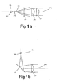
- Figure la shows an arrangement in which a laser diode 22 is used to create a large area parallel light beam 24.
- the laser diode 22 is used to illuminate a spherical ball 25.
- the spherical ball 25 concentrates the laser beam onto a point 26.
- the point source of light may be further refined by passing it through a pin hole (not shown), Past the point 26, the laser light beam is corrected by the use of a transmitting end concave lens 30 and a first transmitting end convex lens 32.
- the light beam is then formed into the parallel beam 24 by a second transmitting end convex lens 34.
- Figure 1b shows an alternative arrangement in which the laser diode 22 is used to create the large area parallel light beam 24.
- a transmitting end aspheric or achromatic lens 35 is used in place of the transmitting end concave lens 30 and first and second transmitting end convex lenses 32 and 34.
- two transmitting end convex lenses may be used in place of the aspheric or achromatic lens 35.
- a transmitting end mirror 37 is used to allow an increase in focal length without significantly increasing the length of the light emitting means arrangement which allows the two series convex lenses to be used with no further correction required.
- Figure 2a shows an arrangement used for focussing the parallel light beam 24 onto the light receiving means 18.
- the arrangement of lenses used is the reverse of that shown in Figure la, in that the light beam 24 is passed through first and second receiving end convex lenses 36 and 38 and a receiving end concave lens 40 in order to focus the beam 24 onto the light receiving means 18.
- Figure 2b shows an alternative arrangement for focussing the parallel light beam 24.
- the arrangement is the reverse of the transmitting end, using a receiving end achromatic or aspheric lens 39 and a receiving end mirror 41.
- two convex receiving lenses may be used in place of the achromatic or aspheric lens 39.
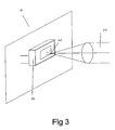
- the light receiving means 18 comprises an aperture 42 in a screen 44 and an image detection device 46.
- the image detection device could be a charge coupled device (CCD) or a projection screen with a camera to observe the projected image.
- the receiving size is preferably smaller than the image detection device 46. In this way, the portion of the image on the image detection device 46 can be used to determine misalignment.
- a high shutter speed may be used to give a strobe effect. Images and in particular the position of obstructions between the strobed images may be determined by interpolation.
- the light emitting means 16 is mounted at one end of the tool 12 of the press brake such that the parallel light beam 24 illuminates a region 20 around the path of movement of the tool 12 which includes the forward edge 48 of the tool 12.
- the light receiving means 18 is mounted at the opposite end of the tool 12 to receive the light beam 24. If an obstruction 50, such as the hand of the operator, enters the region 20, a corresponding shadow 52 will be cast on the image detection device 46.
- the light emitting means 16 and light receiving means 18 are mounted to be stationary relative to the tool 12.
- the safety system also includes a processing and control means (not shown) connected such that the processing and control means receives information from the light receiving means 18 and processes this information and controls operation of the press brake.
- the processing and control means may be in the form of a software program residing on a digital signal processor, a computer or embedded into a microcomputer which receives input from the output of the light receiving means 18.
- the processing and control means captures the images received by the image detection device 46 and processes the images to search for any unknown shadows.
- the processing and control means stores in memory the image received by the image detection device 46 in which no obstructions are present. In the case where the light emitting means 16 and light receiving means 18 are mounted stationary relative to the tool 12, the image includes the forward edge of the tool 12.
- the processing and control means compares the current image received by the image detection device 46 with this stored image to determine the presence of any shadows on the image detection device 46 created by obstructions in the region 20. If any new obstructions are detected, the processing and control means may either stop or slow the movement of the tool 12.
- the processing and control means determines the vertical distance between the tool 12 and the obstruction and allows continued movement of the tool 12 while the distance determined is greater than the distance required to stop the tool 12.
- the processing and control means may also determine the thickness of the shadow cast by the obstruction and allow continued movement of the tool 12 if the thickness is determined to be such that the obstruction could not be part of the operator's body. If the tool 12 is to be stopped, the operator may confirm that continued operation of the tool 12 is safe by an input means, such as a button, arranged to provide a signal to the processing and control means.
- the processing and control means may also create a total picture made up of the image information received by the light receiving means 18 as the tool 12 moves through its path of movement.
- the picture is created and stored in a memory means by the processing and control means. This total picture will be referred to as a shadow map.
- a shadow map 54 is shown in Figure 6 in which no shadows other than those of the tool 12 and anvil 14 are detected. Such a shadow map 54 would be created on a first pass of the tool.
- the processing and control means can store in the memory means a number of known safe shadow maps.
- the known safe shadow maps being shadow maps 54 where no obstruction is detected which would require stopping or slowing of the press brake.
- the shadow map 54 in which the only shadow cast is that of the forward edge of the tool 12 and the anvil would be a known safe shadow map 54.
- a shadow 52 is cast on the image detection device 46.
- the processing means recognises the presence of an unknown shadowed area in the shadow map 54 and halts or slows the movement of the tool until either the shadow disappears by removal of the obstruction or the operator confirms that operation of the press brake is safe to continue by operation of the input means. Further the processing and control means could allow the tool 12 to descend to a point adjacent the obstruction before stopping in order to assist the operator to identify the location of the obstruction which has triggered the deactivation of the press brake.
- the processing and control means stores that shadow map as a known safe shadow map. Therefore, when this work is repeated, the processing and control means automatically recognises the obstruction as being non-hazardous and allows continued operation of the press brake.
- the processing and control means may still however determine that an obstruction is hazardous even if the obstruction has previously been detected and the operator has confirmed it is safe to proceed. For example, if the processing and control means detects a known shadow adjacent an edge of the illuminated region, and the known shadow is determined to be of a sufficient size that it could be hiding a hazardous obstruction, then the processing and control means may need to slow or stop movement of the tool 12, or stop the blade at a suitable distance from the material. To maintain safety requirements, the known safe shadow maps are discarded by the processing and control means if they are not re-detected within a specified time period.
- a tool position detector is required to provide information to the processing and control means as to the position of the tool 12 from the anvil 14 in order to create the full shadow map.
- An alternative embodiment, as shown in Figures 7 and 8 , of the safety system may be provided in which a tool position detector is not used to detect the possible position of the tool 12.
- the processing and control means is arranged to detect the presence of a V-shaped illuminated region 60, being the region defined between the 'V' of the anvil 14 and the work.
- the processing and control means is arranged to define a stop-zone 62, being an area of the illuminated region around the edge of the tool 12. If the stop-zone 62 is obstructed when the V-shaped illuminated region 60 is determined to be an unsafe distance from the point of obstruction, as shown in Figure 8 , then the processing and control means causes the tool 12 to be stopped a safe distance from the material. Operator confirmation is then required to proceed.
- the detection of the presence of the anvil 14 may also be through other means. This may be necessary if, for example, parts of the work obstruct the V-shaped illuminated region 60, preventing accurate detection. Preferably a combination of these techniques would be used.
- the processing and control means also includes means to reduce the possibility of false triggering.
- the processing and control means provides for shadow expansion, whereby the shadow is expanded by a sufficient number of pixels to allow for vibration or other inaccuracies. Also, shadows created while the tool 12 is stopping are ignored due to the possibility of the high deceleration deflecting the light emitting and receiving means 16 and 18. Further, the processing and control means ignores the action of the press brake back gauge. The shape and possible positions of the back gauge are pre-configured into the safety system when the safety system is first commissioned.
- the safety system would preferably be provided with a shadow mask 56, as shown in Figure 5 , placed in front of the light emitting means 16 used for checking that the safety system is receiving the light beam 24 correctly.
- the shadow mask 56 comprises a shape known to the processing and control means, such as a cross 58.
- the processing and control means then checks for the presence of the shadow mask 56 shape and triggers deactivation of the press brake should the shadow mask 56 not be detected.
- shadow masks may be provided at both the light emitting means 16 end and light receiving means 18 end. By ensuring alignment of the shadow masks at each end, alignment of the system can be confirmed or a slight misalignment compensated for.
- the light emitting device may be pulsed such that the light emitting means 16 is turned off or dimmed between each frame being acquired.
- the light emitting means 16 would preferably be turned on for the minimum time period required to activate the image detection device, thus assisting the processing and control means via a strobing effect.
- the processing and control means can use the off or dimmed period to ensure that ambient light does not falsely illuminate the light receiving means 18.
- the safety system may be provided with an output device, such as a screen or computer monitor which displays the images cast on the image detection device 46 and therefore assists the operator in identifying the obstructions detected.
- an output device such as a screen or computer monitor which displays the images cast on the image detection device 46 and therefore assists the operator in identifying the obstructions detected.
- the safety system could also include the use of a quartz deflection device in front of the light transmitting means 16 to correct for vibration and could also employ off-axis parabolic reflectors within the light emitting and receiving means 16 and 18 arrangements to remove the need for lensing and increase the sensing area.
- the processing and control means could analyse the bending of the work in order to reduce the risk of finger entrapment between the work and the tool 12. The movement of shadows that are inconsistent with bending material may also be used to determine an unsafe state.
- the safety system may include vernier adjustments for the direction of the light emitting and/or receiving means 16 and 18 and either adjust the direction automatically or show lights on the device to indicate in which direction the device is out of alignment.
- the light beam 24 is described as a large area parallel light beam, it would be possible to use a matrix of focussed light emitting means and a matrix of discrete sensors.
- a sweet spot pin photodiode could be used with a matrix of light emitting means being pulsed so as to produce a picture.
- a scanning parallel ray laser could be used in place of the matrix of light emitting means.
- the lights in the matrix could be pulsed one after the other in a scanning arrangement or the laser scanned so that the pin photodiode turns on when a parallel ray of light is received from the matrix and stays off when an obstruction casts a shadow.
- a row of sweet spot pin photodiodes could be used and places behind an optical slit. Many wide beam lasers could then be flashed sequentially so as to produce a picture in a similar fashion to that described above.
- the light emitting means 16 and light receiving means 18 could be mounted to be stationary with respect to the anvil 14 rather than the tool 12 and alternative devices could be used for the components of the light emitting means 16, light receiving means 18 and associated optical equipment.
- an off-axis parabolic reflector could be used as a replacement for the mirror and lens arrangements of the embodiment shown in Figures 1b and 2b .
Landscapes
- Engineering & Computer Science (AREA)
- General Engineering & Computer Science (AREA)
- Mechanical Engineering (AREA)
- Presses And Accessory Devices Thereof (AREA)
- Bending Of Plates, Rods, And Pipes (AREA)
- Auxiliary Devices For Machine Tools (AREA)
- Prostheses (AREA)
- Emergency Alarm Devices (AREA)
- Air Bags (AREA)
- Geophysics And Detection Of Objects (AREA)
Claims (23)
- Sicherheitssystem zum Einsatz an einer Maschine mit einem beweglichen Werkzeug (12), welches arrangiert ist, einen bekannten Bewegungsweg zu durchlaufen, wobei das Sicherheitssystem arrangiert ist, das Vorhandensein eines Hindernisses in einem als risikobehaftet eingeschätzten Bereich (20) des Weges zu detektieren, wobei das Sicherheitssystem umfasst: ein lichtemittierendes Mittel (16), das arrangiert ist, allgemein senkrecht zum Bewegungsweg des Werkzeugs (12) verlaufendes Licht zu emittieren, so dass der Bereich (20) beleuchtet wird, ein lichtempfangendes Mittel (18), welches arrangiert ist, von dem lichtemittierenden Mittel (16) Licht zu empfangen, welches durch den Bereich (20) passiert hat; und ein Verarbeitung- und Steuermittel, welches arrangiert ist, Information von dem lichtempfangenden Mittel (18) zu empfangen und zu bestimmen, - aufgrund des Vorhandenseins einer oder mehrerer Schattenregionen, die von dem Hindernis auf das lichtempfangende Mittel (18) geworfen werden - ob ein Hindernis im Bereich (20) vorhanden ist, und die Bewegung des Werkzeugs (12) in Abhängigkeit von dem Vorhandensein eines Hindernisses im Bereich (20) zu steuern, dadurch gekennzeichnet, dass das lichtempfangende Mittel (18) eine Bilddetektierungsvorrichtung (46) umfasst, und
wobei das Verarbeitungs- und Steuermittel konfiguriert ist, die von der Bilddetektierungsvorrichtung (46) empfangenen Bilder zu erfassen und sie durch Suchen nach unbekannten Schatten zu verarbeiten. - Sicherheitssystem nach Anspruch 1, dadurch gekennzeichnet, dass das Verarbeitungs- und Steuermittel Software enthält, die auf einem Computer mit einem Speichermittel residiert, wobei das Verarbeitungs- und Steuermittel das von dem lichtempfangenden Mittel (18) empfangene Bild in dem Speichermittel speichert, wenn im Bereich (20) keine Hindernisse vorhanden sind, und das von dem lichtempfangenden Mittel (18) empfangene aktuelle Bild mit dem gespeicherten Bild des hindernisfreien Bereichs (20) vergleicht und die fortlaufende Bewegung des Werkzeugs (12) gestattet, wenn die Bilder gleich sind.
- Sicherheitssystem nach Anspruch 1 oder 2, dadurch gekennzeichnet, dass das Verarbeitungs- und Steuermittel die Bewegung des Werkzeugs (12) entweder verlangsamt oder stoppt, wenn das Verarbeitungs- und Steuermittel das Vorhandensein eines Hindernisses im Bereich (20) feststellt.
- Sicherheitssystem nach Anspruch 3, dadurch gekennzeichnet, dass ein Eingabemittel vorgesehen ist, derart, dass, wenn das Verarbeitungs- und Steuermittel die Bewegung des Werkzeugs (12) verlangsamt oder stoppt, es durch die Betätigung des Eingabemittels durch den Bediener informiert wird, dass die fortlaufende Bewegung des Werkzeugs (12) sicher ist, so dass das Verarbeitungs- und Steuermittel die Bewegung des Werkzeugs (12) wiederaufnehmen kann.
- Sicherheitssystem nach einem der vorhergehenden Ansprüche, wobei das Verarbeitungs- und Steuermittel arrangiert ist, den senkrechten Abstand einer vorderen Kante des Werkzeugs (12) von einem einen Schatten auf das lichtempfangende Mittel (18) werfenden Hindernis zu bestimmen, und die fortlaufende Bewegung des Werkzeugs (12) zu gestatten, wenn der so bestimmte Abstand größer als der zum Stoppen des Werkzeugs (12) benötigte Abstand ist.
- Sicherheitssystem nach Anspruch 5, dadurch gekennzeichnet, dass das Verarbeitungs- und Steuermittel arrangiert ist, die Dicke eines einen Schatten auf das lichtempfangende Mittel (18) werfenden Hindernisses zu bestimmen, und falls die Dicke geringer als ein vorherbestimmter Wert ist, die fortlaufende Bewegung des Werkzeugs (12) zu gestatten, wobei der vorherbestimmte Wert als so klein bestimmt wird, dass das Hindernis nicht Teil des Körpers des Bedieners sein kann.
- Sicherheitssystem nach einem der Ansprüche 2 bis 6, dadurch gekennzeichnet, dass das Verarbeitungs- und Steuermittel im Speichermittel eine oder mehrere Abbildungen speichert, die aus Bildinformation bestehen, die während des Passierens des Bewegungswegs des Werkzeugs (12) von dem lichtempfangenden Mittel (18) empfangen wurden, wobei die oder jede Abbildung als sicher für die fortlaufende Bewegung des Werkzeugs (12) bestimmt wird.
- Sicherheitssystem nach Anspruch 7, dadurch gekennzeichnet, dass das Verarbeitungs- und Steuermittel das von dem lichtempfangenden Mittel (18) empfangene Bild mit den im Speichermittel gespeicherten Abbildungen vergleicht und den fortlaufenden Betrieb des Werkzeugs (12) gestattet, wenn sie gleich sind.
- Sicherheitssystem nach Anspruch 7, dadurch gekennzeichnet, dass der Bediener mit einem Mittel versehen ist, das Verarbeitungs- und Steuermittel anzuweisen, die durch den aktuellen Durchgang des Werkzeugs (12) erzeugte Bildinformation in dem Speichermittel als sichere Abbildung zu speichern.
- Sicherheitssystem nach einem der vorhergehenden Ansprüche, dadurch gekennzeichnet, dass das lichtemittierende Mittel (16) einen allgemein parallelen Lichtstrahl erzeugt.
- Sicherheitssystem nach einem der vorhergehenden Ansprüche, dadurch gekennzeichnet, dass das lichtempfangende Mittel (18) ein ladungsgekoppeltes Bauelement ist.
- Sicherheitssystem nach einem der vorhergehenden Ansprüche, dadurch gekennzeichnet, dass das lichtempfangende Mittel (18) einen Projektionsbildschirm und eine Kamera umfasst, um das Bild auf dem Projektionsbildschirm beobachten zu können.
- Sicherheitssystem nach Anspruch 12, dadurch gekennzeichnet, dass das ladungsgekoppelte Bauelement eine relativ schnelle Verschlussgeschwindigkeit nutzt, um Einflüsse des Umgebungslichts zu reduzieren.
- Sicherheitssystem nach einem der vorhergehenden Ansprüche, dadurch gekennzeichnet, dass das lichtempfangende Mittel (18) und das lichtemittierende Mittel (16) relativ zum Werkzeug (12) stationär befestigt sind.
- Sicherheitssystem nach einem der vorhergehenden Ansprüche, dadurch gekennzeichnet, dass am lichtemittierenden Mittel (16) eine Schattenmaske vorgesehen ist und das Verarbeitungs- und Steuermittel arrangiert ist, den von der Schattenmaske auf dem lichtempfangenden Mittel (18) erzeugten Schatten zu erkennen, um zu bestimmen, dass das lichtemittierende Mittel (16) funktioniert.
- Sicherheitssystem nach Anspruch 15, dadurch gekennzeichnet, dass auch an dem lichtempfangenden Mittel (18) eine zweite Schattenmaske vorgesehen ist und das Verarbeitungs- und Steuermittel arrangiert ist zu detektieren, ob die Schattenmaske des lichtemittierenden Mittels (16) mit der zweiten Schattenmaske des lichtempfangenden Mittels (18) fluchtet, um zu bestimmen, ob das Sicherheitssystem korrekt ausgerichtet ist.
- Sicherheitssystem nach einem der vorhergehenden Ansprüche, dadurch gekennzeichnet, dass eine Anzeigevorrichtung vorgesehen ist, um die von dem lichtempfangenden Mittel (18) empfangenen Bilder anzuzeigen.
- Sicherheitssystem nach einem der vorhergehenden Ansprüche, dadurch gekennzeichnet, dass das lichtemittierende Mittel (16) eine Lichtquelle und eine oder mehrere übertragungsseitigen Linsen umfasst, wobei die Lichtquelle arrangiert ist, allgemein parallel zu einer parallel zur vorderen Kante des Werkzeugs (12) verlaufenden Achse und durch den Bereich (20) hindurch zu übertragen.
- Sicherheitssystem nach einem der vorhergehenden Ansprüche, dadurch gekennzeichnet, dass eine oder mehrere empfangsseitigen Linsen neben dem lichtempfangenden Mittel (18) vorgesehen sind und das lichtempfangende Mittel (18) ausgerichtet ist, durch die empfangsseitigen Linsen hindurch laufendes Licht zu empfangen.
- Sicherheitssystem nach einem der Ansprüche 1 bis 17, dadurch gekennzeichnet, dass das lichtemittierende Mittel (16) eine Lichtquelle und einen übertragungsseitigen Spiegel beinhaltet, wobei die Lichtquelle arrangiert ist, allgemein senkrecht zu einer parallel zur vorderen Kante des Werkzeugs (12) verlaufenden Achse verlaufendes Licht zum übertragungsseitigen Spiegel hin zu übertragen, wodurch das Licht derart reflektiert wird, das es den Bereich (20) durchläuft.
- Sicherheitssystem nach Anspruch 19, dadurch gekennzeichnet, dass das Übertragungsmittel zwei übertragungsseitige konvexe Linsen beinhaltet, die derart arrangiert sind, dass das von dem übertragungsseitigen Spiegel reflektierte Licht durch die zwei übertragungsseitigen konvexen Linsen hindurch läuft.
- Sicherheitssystem nach einem der vorhergehenden Ansprüche, dadurch gekennzeichnet, dass neben dem lichtempfangenden Mittel (18) ein empfangsseitiger Spiegel vorgesehen ist, welcher derart arrangiert ist, dass er Licht reflektiert, welches durch den Bereich (20) hindurch zum lichtempfangenden Mittel (18) hin gelaufen ist, wobei das lichtempfangende Mittel (18) derart arrangiert ist, das es Licht empfängt, das allgemein senkrecht zu der parallel zur vorderen Kante des Werkzeugs (12) verlaufenden Achse verläuft.
- Sicherheitssystem nach Anspruch 22, dadurch gekennzeichnet, dass zwei empfangsseitige konvexe Linsen vorgesehen sind, die derart arrangiert sind, dass das entlang der Achse parallel zur vorderen Kante verlaufende Licht die zwei empfangsseitigen konvexen Linsen durchläuft, bevor es von dem übertragungsseitigen Spiegel reflektiert wird.
Applications Claiming Priority (7)
| Application Number | Priority Date | Filing Date | Title |
|---|---|---|---|
| AUPS2878A AUPS287802A0 (en) | 2002-06-11 | 2002-06-11 | Reliable detection techniques using parallel wide beam optics |
| AU2002002878 | 2002-06-11 | ||
| AU2002950078 | 2002-07-10 | ||
| AU2002950078A AU2002950078A0 (en) | 2002-07-10 | 2002-07-10 | A safety system |
| AU2002951351A AU2002951351A0 (en) | 2002-09-12 | 2002-09-12 | Reliable detection techniques using parallel wide beam optics 2 |
| AU2002951351 | 2002-09-12 | ||
| PCT/AU2003/000707 WO2003104711A1 (en) | 2002-06-11 | 2003-06-10 | A safety system |
Publications (3)
| Publication Number | Publication Date |
|---|---|
| EP1552214A1 EP1552214A1 (de) | 2005-07-13 |
| EP1552214A4 EP1552214A4 (de) | 2006-08-02 |
| EP1552214B1 true EP1552214B1 (de) | 2011-10-26 |
Family
ID=29740320
Family Applications (1)
| Application Number | Title | Priority Date | Filing Date |
|---|---|---|---|
| EP03724665A Expired - Lifetime EP1552214B1 (de) | 2002-06-11 | 2003-06-10 | Sicherheitssystem |
Country Status (9)
| Country | Link |
|---|---|
| US (1) | US7448241B2 (de) |
| EP (1) | EP1552214B1 (de) |
| JP (1) | JP4511345B2 (de) |
| CN (1) | CN1659405B (de) |
| AT (1) | ATE530842T1 (de) |
| AU (1) | AU2003229135B2 (de) |
| CA (1) | CA2487035C (de) |
| NZ (1) | NZ537461A (de) |
| WO (1) | WO2003104711A1 (de) |
Families Citing this family (18)
| Publication number | Priority date | Publication date | Assignee | Title |
|---|---|---|---|---|
| DE10327388C5 (de) * | 2003-06-18 | 2011-12-08 | Leuze Lumiflex Gmbh + Co. Kg | Schutzeinrichtung |
| DE102004017285A1 (de) * | 2004-04-08 | 2005-10-27 | Sick Ag | Verfahren zur Justage einer Sicherheitseinrichtung und optoelektronische Sicherheitseinrichtung |
| DE102004020024A1 (de) * | 2004-04-23 | 2005-11-10 | Sick Ag | Verfahren zur Sicherung einer Werkzeugmaschine und optoelektronischer Sensor zur Durchführung eines solchen Verfahrens |
| DE102004043514A1 (de) * | 2004-09-08 | 2006-03-09 | Sick Ag | Verfahren und Vorrichtung zum Steuern einer sicherheitsrelevanten Funktion einer Maschine |
| US8101917B2 (en) | 2006-06-26 | 2012-01-24 | Qualex Manufacturing Llc | Method and apparatus for detecting unsafe conditions |
| US7439512B2 (en) * | 2006-06-26 | 2008-10-21 | Qualex Manufacturing Llc | Method and apparatus for detecting unsafe conditions |
| DE102007006306A1 (de) * | 2007-01-30 | 2008-07-31 | Pilz Gmbh & Co. Kg | Sicherheitseinrichtung für eine Maschine |
| DE102008023294B4 (de) * | 2008-01-16 | 2010-02-04 | Cedes Ag | Sicherungssystem zur Absicherung eines sich bewegenden, geführten Bewegungselements gegen ungewollte Kollisionen |
| CN101260971B (zh) * | 2008-04-21 | 2010-06-02 | 东莞合迅服装设计有限公司 | 一种超声波机安全装置及采用该安全装置的超声波机的控制方法 |
| DE102008054698A1 (de) * | 2008-12-16 | 2010-06-17 | Robert Bosch Gmbh | Werkzeugmaschine |
| US8314393B2 (en) | 2008-12-23 | 2012-11-20 | Qualex Manufacturing, Lc | Method and apparatus for detecting unsafe conditions |
| CN102810239A (zh) * | 2011-05-31 | 2012-12-05 | 鸿富锦精密工业(深圳)有限公司 | 意外防止系统及方法 |
| US9383061B2 (en) * | 2011-07-14 | 2016-07-05 | Citizen Holdings Co., Ltd. | Machine tool and drive regulation device for said machine tool |
| USD705625S1 (en) | 2013-05-21 | 2014-05-27 | Edgecraft Corporation | Combination sharpener having two sharpening components |
| US9656372B2 (en) | 2015-01-16 | 2017-05-23 | Edgecraft Corporation | Sharpener for thick knives |
| AT518894B1 (de) | 2016-09-02 | 2018-02-15 | Trumpf Maschinen Austria Gmbh & Co Kg | Biegemaschine mit einer Biegeinformations-Anzeigevorrichtung |
| US10725445B2 (en) | 2016-11-11 | 2020-07-28 | Safe Tek, LLC | Systems, methods, and articles of manufacture for operation of an industrial machine |
| WO2021146575A1 (en) * | 2020-01-17 | 2021-07-22 | ColDesi, Inc. | Compact in-line heat press |
Family Cites Families (16)
| Publication number | Priority date | Publication date | Assignee | Title |
|---|---|---|---|---|
| US4660703A (en) * | 1983-11-07 | 1987-04-28 | Nevio Filcich | Method and apparatus for machine safety |
| CH665364A5 (fr) * | 1985-10-30 | 1988-05-13 | Cybelec Sa | Dispositif pour le controle automatique de l'operation de pliage lors du pliage avec une presse-plieuse. |
| DE3641926C1 (de) * | 1986-12-09 | 1988-04-28 | Sick Optik Elektronik Erwin | Autokollimationslichtvorhang |
| AU667057B2 (en) * | 1991-10-18 | 1996-03-07 | Thomas John Appleyard | Brake press safety apparatus |
| US5243183A (en) * | 1992-09-15 | 1993-09-07 | Triad Controls, Inc. | Obstruction position detecting system with comparison and memory means |
| AUPN744696A0 (en) * | 1996-01-05 | 1996-02-01 | Appleyard, Thomas John | Safety apparatus and protection method for machines |
| IT1305525B1 (it) * | 1998-10-21 | 2001-05-09 | Electrolux Zanussi Grandi Impi | Dispositivo per evitare infortuni all'operatore di unapressa piegatrice |
| US6444973B1 (en) * | 1999-01-12 | 2002-09-03 | James R. Dissey | Method and apparatus for improving the accuracy of a region-based light detector |
| AUPQ022199A0 (en) * | 1999-05-05 | 1999-06-03 | Lazer Safe Pty Ltd | Industrial press safety system |
| JP3603084B2 (ja) * | 1999-07-02 | 2004-12-15 | 独立行政法人産業安全研究所 | ブランキングシステム |
| DE10033608A1 (de) * | 2000-07-11 | 2002-02-07 | Pilz Gmbh & Co | Verfahren und Vorrichtung zum Absichern eines Gefahrenbereichs, insbesondere des Gefahrenbereichs einer automatisiert arbeitenden Maschine |
| US6644080B2 (en) * | 2001-01-12 | 2003-11-11 | Finn-Power International, Inc. | Press brake worksheet positioning system |
| DE10114784A1 (de) | 2001-03-26 | 2002-10-10 | Sick Ag | Vorrichtung zur Überwachung eines Schutzfeldes |
| DE10143505B4 (de) * | 2001-09-05 | 2010-07-08 | Sick Ag | Sicherungsverfahren und optoelektronischer Sensor |
| DE10152543A1 (de) * | 2001-10-24 | 2003-05-08 | Sick Ag | Verfahren und Vorrichtung zum Steuern einer sicherheitsrelevanten Funktion einer Maschine |
| AUPS140902A0 (en) | 2002-03-27 | 2002-05-09 | Lazer Safe Pty Ltd | Multiple laser safety system |
-
2003
- 2003-06-10 US US10/517,802 patent/US7448241B2/en not_active Expired - Lifetime
- 2003-06-10 JP JP2004511741A patent/JP4511345B2/ja not_active Expired - Fee Related
- 2003-06-10 CA CA2487035A patent/CA2487035C/en not_active Expired - Fee Related
- 2003-06-10 WO PCT/AU2003/000707 patent/WO2003104711A1/en not_active Ceased
- 2003-06-10 CN CN03813537XA patent/CN1659405B/zh not_active Expired - Lifetime
- 2003-06-10 AT AT03724665T patent/ATE530842T1/de not_active IP Right Cessation
- 2003-06-10 NZ NZ537461A patent/NZ537461A/en not_active IP Right Cessation
- 2003-06-10 EP EP03724665A patent/EP1552214B1/de not_active Expired - Lifetime
- 2003-06-10 AU AU2003229135A patent/AU2003229135B2/en not_active Expired
Also Published As
| Publication number | Publication date |
|---|---|
| AU2003229135A1 (en) | 2003-12-22 |
| EP1552214A4 (de) | 2006-08-02 |
| JP2005528992A (ja) | 2005-09-29 |
| CA2487035C (en) | 2012-06-05 |
| JP4511345B2 (ja) | 2010-07-28 |
| CA2487035A1 (en) | 2003-12-18 |
| US20050241355A1 (en) | 2005-11-03 |
| EP1552214A1 (de) | 2005-07-13 |
| NZ537461A (en) | 2007-10-26 |
| CN1659405B (zh) | 2012-06-27 |
| CN1659405A (zh) | 2005-08-24 |
| WO2003104711A1 (en) | 2003-12-18 |
| ATE530842T1 (de) | 2011-11-15 |
| AU2003229135B2 (en) | 2007-05-17 |
| US7448241B2 (en) | 2008-11-11 |
Similar Documents
| Publication | Publication Date | Title |
|---|---|---|
| CA2487035C (en) | A safety system for use with a tool machine | |
| US20140293039A1 (en) | Imaging and safety system and method for an industrial machine | |
| US20030076224A1 (en) | Method of, and apparatus for, controlling a safety-specific function of a machine | |
| US20050235790A1 (en) | Method for securing a machine tool and opto-electronic sensor for carrying out such a method | |
| JP5537027B2 (ja) | 産業機械用の画像化および安全システムならびに方法 | |
| JP2005528992A5 (de) | ||
| US9346091B2 (en) | Safety device for a machine in which a first machine part performs a working movement with respect to a second machine part | |
| US7034929B2 (en) | Protective apparatus for the monitoring of a protected zone to be moved with a component | |
| JP2005043868A (ja) | 画像投射装置及び画像投射方法 | |
| US7963137B2 (en) | Apparatus comprising a protection device | |
| JP2007198594A (ja) | 防護域の監視装置 | |
| ZA200500017B (en) | A safety system | |
| RU2372552C2 (ru) | Защитная система | |
| JP4958557B2 (ja) | 制御システム | |
| JP7413347B2 (ja) | 曲げプレス機を操作する方法 | |
| US20070214854A1 (en) | Saftey Method and Saftey Device for a Machine, Especially a Bending Press | |
| JP2006061959A (ja) | プレスブレーキ | |
| AU2014277796B2 (en) | Imaging and safety system & method for an industrial machine | |
| US20040130627A1 (en) | Triggering of image recordings | |
| JP3282227B2 (ja) | 侵入検知器 | |
| ZA200605725B (en) | A control system | |
| AU2006261576A1 (en) | Imaging and safety system and method for an industrial machine | |
| AU2012216571A1 (en) | Imaging and safety system & method for an industrial machine |
Legal Events
| Date | Code | Title | Description |
|---|---|---|---|
| PUAI | Public reference made under article 153(3) epc to a published international application that has entered the european phase |
Free format text: ORIGINAL CODE: 0009012 |
|
| 17P | Request for examination filed |
Effective date: 20050111 |
|
| AK | Designated contracting states |
Kind code of ref document: A1 Designated state(s): AT BE BG CH CY CZ DE DK EE ES FI FR GB GR HU IE IT LI LU MC NL PT RO SE SI SK TR |
|
| AX | Request for extension of the european patent |
Extension state: AL LT LV MK |
|
| DAX | Request for extension of the european patent (deleted) | ||
| A4 | Supplementary search report drawn up and despatched |
Effective date: 20060703 |
|
| 17Q | First examination report despatched |
Effective date: 20061116 |
|
| GRAP | Despatch of communication of intention to grant a patent |
Free format text: ORIGINAL CODE: EPIDOSNIGR1 |
|
| GRAS | Grant fee paid |
Free format text: ORIGINAL CODE: EPIDOSNIGR3 |
|
| GRAA | (expected) grant |
Free format text: ORIGINAL CODE: 0009210 |
|
| AK | Designated contracting states |
Kind code of ref document: B1 Designated state(s): AT BE BG CH CY CZ DE DK EE ES FI FR GB GR HU IE IT LI LU MC NL PT RO SE SI SK TR |
|
| REG | Reference to a national code |
Ref country code: GB Ref legal event code: FG4D |
|
| REG | Reference to a national code |
Ref country code: CH Ref legal event code: EP |
|
| REG | Reference to a national code |
Ref country code: IE Ref legal event code: FG4D |
|
| REG | Reference to a national code |
Ref country code: DE Ref legal event code: R096 Ref document number: 60338903 Country of ref document: DE Effective date: 20111222 |
|
| REG | Reference to a national code |
Ref country code: NL Ref legal event code: VDEP Effective date: 20111026 |
|
| REG | Reference to a national code |
Ref country code: AT Ref legal event code: MK05 Ref document number: 530842 Country of ref document: AT Kind code of ref document: T Effective date: 20111026 |
|
| PG25 | Lapsed in a contracting state [announced via postgrant information from national office to epo] |
Ref country code: GR Free format text: LAPSE BECAUSE OF FAILURE TO SUBMIT A TRANSLATION OF THE DESCRIPTION OR TO PAY THE FEE WITHIN THE PRESCRIBED TIME-LIMIT Effective date: 20120127 Ref country code: PT Free format text: LAPSE BECAUSE OF FAILURE TO SUBMIT A TRANSLATION OF THE DESCRIPTION OR TO PAY THE FEE WITHIN THE PRESCRIBED TIME-LIMIT Effective date: 20120227 Ref country code: SE Free format text: LAPSE BECAUSE OF FAILURE TO SUBMIT A TRANSLATION OF THE DESCRIPTION OR TO PAY THE FEE WITHIN THE PRESCRIBED TIME-LIMIT Effective date: 20111026 Ref country code: SI Free format text: LAPSE BECAUSE OF FAILURE TO SUBMIT A TRANSLATION OF THE DESCRIPTION OR TO PAY THE FEE WITHIN THE PRESCRIBED TIME-LIMIT Effective date: 20111026 Ref country code: NL Free format text: LAPSE BECAUSE OF FAILURE TO SUBMIT A TRANSLATION OF THE DESCRIPTION OR TO PAY THE FEE WITHIN THE PRESCRIBED TIME-LIMIT Effective date: 20111026 |
|
| PG25 | Lapsed in a contracting state [announced via postgrant information from national office to epo] |
Ref country code: CY Free format text: LAPSE BECAUSE OF FAILURE TO SUBMIT A TRANSLATION OF THE DESCRIPTION OR TO PAY THE FEE WITHIN THE PRESCRIBED TIME-LIMIT Effective date: 20111026 |
|
| PG25 | Lapsed in a contracting state [announced via postgrant information from national office to epo] |
Ref country code: EE Free format text: LAPSE BECAUSE OF FAILURE TO SUBMIT A TRANSLATION OF THE DESCRIPTION OR TO PAY THE FEE WITHIN THE PRESCRIBED TIME-LIMIT Effective date: 20111026 Ref country code: DK Free format text: LAPSE BECAUSE OF FAILURE TO SUBMIT A TRANSLATION OF THE DESCRIPTION OR TO PAY THE FEE WITHIN THE PRESCRIBED TIME-LIMIT Effective date: 20111026 Ref country code: SK Free format text: LAPSE BECAUSE OF FAILURE TO SUBMIT A TRANSLATION OF THE DESCRIPTION OR TO PAY THE FEE WITHIN THE PRESCRIBED TIME-LIMIT Effective date: 20111026 Ref country code: CZ Free format text: LAPSE BECAUSE OF FAILURE TO SUBMIT A TRANSLATION OF THE DESCRIPTION OR TO PAY THE FEE WITHIN THE PRESCRIBED TIME-LIMIT Effective date: 20111026 Ref country code: BG Free format text: LAPSE BECAUSE OF FAILURE TO SUBMIT A TRANSLATION OF THE DESCRIPTION OR TO PAY THE FEE WITHIN THE PRESCRIBED TIME-LIMIT Effective date: 20120126 |
|
| PG25 | Lapsed in a contracting state [announced via postgrant information from national office to epo] |
Ref country code: RO Free format text: LAPSE BECAUSE OF FAILURE TO SUBMIT A TRANSLATION OF THE DESCRIPTION OR TO PAY THE FEE WITHIN THE PRESCRIBED TIME-LIMIT Effective date: 20111026 |
|
| PLBE | No opposition filed within time limit |
Free format text: ORIGINAL CODE: 0009261 |
|
| STAA | Information on the status of an ep patent application or granted ep patent |
Free format text: STATUS: NO OPPOSITION FILED WITHIN TIME LIMIT |
|
| 26N | No opposition filed |
Effective date: 20120727 |
|
| REG | Reference to a national code |
Ref country code: DE Ref legal event code: R097 Ref document number: 60338903 Country of ref document: DE Effective date: 20120727 |
|
| PG25 | Lapsed in a contracting state [announced via postgrant information from national office to epo] |
Ref country code: MC Free format text: LAPSE BECAUSE OF NON-PAYMENT OF DUE FEES Effective date: 20120630 Ref country code: AT Free format text: LAPSE BECAUSE OF FAILURE TO SUBMIT A TRANSLATION OF THE DESCRIPTION OR TO PAY THE FEE WITHIN THE PRESCRIBED TIME-LIMIT Effective date: 20111026 |
|
| REG | Reference to a national code |
Ref country code: CH Ref legal event code: PL |
|
| REG | Reference to a national code |
Ref country code: CH Ref legal event code: PL |
|
| REG | Reference to a national code |
Ref country code: IE Ref legal event code: MM4A |
|
| PG25 | Lapsed in a contracting state [announced via postgrant information from national office to epo] |
Ref country code: LI Free format text: LAPSE BECAUSE OF NON-PAYMENT OF DUE FEES Effective date: 20120630 Ref country code: CH Free format text: LAPSE BECAUSE OF NON-PAYMENT OF DUE FEES Effective date: 20120630 Ref country code: ES Free format text: LAPSE BECAUSE OF FAILURE TO SUBMIT A TRANSLATION OF THE DESCRIPTION OR TO PAY THE FEE WITHIN THE PRESCRIBED TIME-LIMIT Effective date: 20120206 Ref country code: IE Free format text: LAPSE BECAUSE OF NON-PAYMENT OF DUE FEES Effective date: 20120610 |
|
| PG25 | Lapsed in a contracting state [announced via postgrant information from national office to epo] |
Ref country code: FI Free format text: LAPSE BECAUSE OF FAILURE TO SUBMIT A TRANSLATION OF THE DESCRIPTION OR TO PAY THE FEE WITHIN THE PRESCRIBED TIME-LIMIT Effective date: 20111026 |
|
| PG25 | Lapsed in a contracting state [announced via postgrant information from national office to epo] |
Ref country code: TR Free format text: LAPSE BECAUSE OF FAILURE TO SUBMIT A TRANSLATION OF THE DESCRIPTION OR TO PAY THE FEE WITHIN THE PRESCRIBED TIME-LIMIT Effective date: 20111026 |
|
| PG25 | Lapsed in a contracting state [announced via postgrant information from national office to epo] |
Ref country code: LU Free format text: LAPSE BECAUSE OF NON-PAYMENT OF DUE FEES Effective date: 20120610 |
|
| PG25 | Lapsed in a contracting state [announced via postgrant information from national office to epo] |
Ref country code: HU Free format text: LAPSE BECAUSE OF FAILURE TO SUBMIT A TRANSLATION OF THE DESCRIPTION OR TO PAY THE FEE WITHIN THE PRESCRIBED TIME-LIMIT Effective date: 20030610 |
|
| REG | Reference to a national code |
Ref country code: FR Ref legal event code: PLFP Year of fee payment: 14 |
|
| REG | Reference to a national code |
Ref country code: FR Ref legal event code: PLFP Year of fee payment: 15 |
|
| PGFP | Annual fee paid to national office [announced via postgrant information from national office to epo] |
Ref country code: GB Payment date: 20190611 Year of fee payment: 17 |
|
| GBPC | Gb: european patent ceased through non-payment of renewal fee |
Effective date: 20200610 |
|
| PG25 | Lapsed in a contracting state [announced via postgrant information from national office to epo] |
Ref country code: GB Free format text: LAPSE BECAUSE OF NON-PAYMENT OF DUE FEES Effective date: 20200610 |
|
| PGFP | Annual fee paid to national office [announced via postgrant information from national office to epo] |
Ref country code: IT Payment date: 20220623 Year of fee payment: 20 Ref country code: DE Payment date: 20220609 Year of fee payment: 20 |
|
| PGFP | Annual fee paid to national office [announced via postgrant information from national office to epo] |
Ref country code: BE Payment date: 20220620 Year of fee payment: 20 |
|
| PGFP | Annual fee paid to national office [announced via postgrant information from national office to epo] |
Ref country code: FR Payment date: 20220607 Year of fee payment: 20 |
|
| REG | Reference to a national code |
Ref country code: DE Ref legal event code: R071 Ref document number: 60338903 Country of ref document: DE |
|
| REG | Reference to a national code |
Ref country code: BE Ref legal event code: MK Effective date: 20230610 |