EP1552279B1 - Systeme et procedes d'extension de gamme dynamique au moyen d'un echantillonnage temporel par integration a longueur variable - Google Patents
Systeme et procedes d'extension de gamme dynamique au moyen d'un echantillonnage temporel par integration a longueur variable Download PDFInfo
- Publication number
- EP1552279B1 EP1552279B1 EP03770710A EP03770710A EP1552279B1 EP 1552279 B1 EP1552279 B1 EP 1552279B1 EP 03770710 A EP03770710 A EP 03770710A EP 03770710 A EP03770710 A EP 03770710A EP 1552279 B1 EP1552279 B1 EP 1552279B1
- Authority
- EP
- European Patent Office
- Prior art keywords
- signal
- signal value
- interval
- integration time
- short
- Prior art date
- Legal status (The legal status is an assumption and is not a legal conclusion. Google has not performed a legal analysis and makes no representation as to the accuracy of the status listed.)
- Expired - Lifetime
Links
Images




Classifications
-
- G—PHYSICS
- G01—MEASURING; TESTING
- G01N—INVESTIGATING OR ANALYSING MATERIALS BY DETERMINING THEIR CHEMICAL OR PHYSICAL PROPERTIES
- G01N21/00—Investigating or analysing materials by the use of optical means, i.e. using sub-millimetre waves, infrared, visible or ultraviolet light
- G01N21/17—Systems in which incident light is modified in accordance with the properties of the material investigated
- G01N21/25—Colour; Spectral properties, i.e. comparison of effect of material on the light at two or more different wavelengths or wavelength bands
- G01N21/27—Colour; Spectral properties, i.e. comparison of effect of material on the light at two or more different wavelengths or wavelength bands using photo-electric detection ; circuits for computing concentration
- G01N21/274—Calibration, base line adjustment, drift correction
-
- G—PHYSICS
- G01—MEASURING; TESTING
- G01J—MEASUREMENT OF INTENSITY, VELOCITY, SPECTRAL CONTENT, POLARISATION, PHASE OR PULSE CHARACTERISTICS OF INFRARED, VISIBLE OR ULTRAVIOLET LIGHT; COLORIMETRY; RADIATION PYROMETRY
- G01J1/00—Photometry, e.g. photographic exposure meter
- G01J1/42—Photometry, e.g. photographic exposure meter using electric radiation detectors
-
- G—PHYSICS
- G01—MEASURING; TESTING
- G01N—INVESTIGATING OR ANALYSING MATERIALS BY DETERMINING THEIR CHEMICAL OR PHYSICAL PROPERTIES
- G01N21/00—Investigating or analysing materials by the use of optical means, i.e. using sub-millimetre waves, infrared, visible or ultraviolet light
- G01N21/62—Systems in which the material investigated is excited whereby it emits light or causes a change in wavelength of the incident light
- G01N21/63—Systems in which the material investigated is excited whereby it emits light or causes a change in wavelength of the incident light optically excited
- G01N21/64—Fluorescence; Phosphorescence
- G01N21/645—Specially adapted constructive features of fluorimeters
-
- H—ELECTRICITY
- H03—ELECTRONIC CIRCUITRY
- H03F—AMPLIFIERS
- H03F3/00—Amplifiers with only discharge tubes or only semiconductor devices as amplifying elements
- H03F3/04—Amplifiers with only discharge tubes or only semiconductor devices as amplifying elements with semiconductor devices only
- H03F3/08—Amplifiers with only discharge tubes or only semiconductor devices as amplifying elements with semiconductor devices only controlled by light
-
- H—ELECTRICITY
- H04—ELECTRIC COMMUNICATION TECHNIQUE
- H04N—PICTORIAL COMMUNICATION, e.g. TELEVISION
- H04N23/00—Cameras or camera modules comprising electronic image sensors; Control thereof
- H04N23/70—Circuitry for compensating brightness variation in the scene
-
- H—ELECTRICITY
- H04—ELECTRIC COMMUNICATION TECHNIQUE
- H04N—PICTORIAL COMMUNICATION, e.g. TELEVISION
- H04N23/00—Cameras or camera modules comprising electronic image sensors; Control thereof
- H04N23/70—Circuitry for compensating brightness variation in the scene
- H04N23/73—Circuitry for compensating brightness variation in the scene by influencing the exposure time
-
- H—ELECTRICITY
- H04—ELECTRIC COMMUNICATION TECHNIQUE
- H04N—PICTORIAL COMMUNICATION, e.g. TELEVISION
- H04N23/00—Cameras or camera modules comprising electronic image sensors; Control thereof
- H04N23/70—Circuitry for compensating brightness variation in the scene
- H04N23/741—Circuitry for compensating brightness variation in the scene by increasing the dynamic range of the image compared to the dynamic range of the electronic image sensors
-
- H—ELECTRICITY
- H04—ELECTRIC COMMUNICATION TECHNIQUE
- H04N—PICTORIAL COMMUNICATION, e.g. TELEVISION
- H04N23/00—Cameras or camera modules comprising electronic image sensors; Control thereof
- H04N23/70—Circuitry for compensating brightness variation in the scene
- H04N23/76—Circuitry for compensating brightness variation in the scene by influencing the image signals
-
- H—ELECTRICITY
- H04—ELECTRIC COMMUNICATION TECHNIQUE
- H04N—PICTORIAL COMMUNICATION, e.g. TELEVISION
- H04N25/00—Circuitry of solid-state image sensors [SSIS]; Control thereof
- H04N25/50—Control of the SSIS exposure
- H04N25/57—Control of the dynamic range
- H04N25/58—Control of the dynamic range involving two or more exposures
- H04N25/587—Control of the dynamic range involving two or more exposures acquired sequentially, e.g. using the combination of odd and even image fields
- H04N25/589—Control of the dynamic range involving two or more exposures acquired sequentially, e.g. using the combination of odd and even image fields with different integration times, e.g. short and long exposures
-
- G—PHYSICS
- G01—MEASURING; TESTING
- G01N—INVESTIGATING OR ANALYSING MATERIALS BY DETERMINING THEIR CHEMICAL OR PHYSICAL PROPERTIES
- G01N2201/00—Features of devices classified in G01N21/00
- G01N2201/12—Circuits of general importance; Signal processing
- G01N2201/124—Sensitivity
- G01N2201/1241—Multirange
Definitions
- the present teachings generally relate to methods, software and apparatus useful for signal processing and, in various embodiments, to a system and method for resolving signals generated by a charge coupled device.
- CCD charge coupled devices
- CCD charge coupled devices
- conventional CCD's comprise one or more light-detecting elements that may be sensitive enough to detect as little as a few photo electrons. It is often desirable for a CCD device to possess a dynamic range of detection that extends several orders of magnitude with respect to the number of detectable photo electrons.
- Conventional solutions to increasing the dynamic range may include increasing the number of bits of analog-to-digital converters (ADC) associated with the CCD. This increase in the number of bits, however, also increases the cost of manufacture and processing time of the CCD.
- ADC analog-to-digital converters
- Another method for extending the dynamic range may involve splitting of the signal from a selected element into multiple signals that are hardware resolved.
- Each signal may further be provided with a different gain to thereby allow the split signals to collectively cover a wider dynamic range than that of a single signal.
- Such a hardware adaptation for dynamic range enhancement often requires costly retrofitting of the instrument and may not be practical to implement with existing devices. From the foregoing, it will be appreciated that there is a need for an alternative method by which the dynamic range of a CCD or other photo-detector device may be improved. Furthermore, there is a need for a dynamic range extension methodology that may be adapted for use with existing systems without necessitating significant hardware modifications.
- US 2002/0122126 discloses performing correlated double sampling (CDS) in a CMOS image sensor to reduce RESET noise: a first sampled signal is detected after resetting the pixels, a second sampled value is determined at the end of an exposure time, and a differential signal substantially free from RESET noise is formed by subtracting the first sampled value from the second sampled value.
- CDS correlated double sampling
- the first sampled signal is obtained only after a certain delay interval so that this signal too contains not only a noise component but also brightness information. If the second sampled signal exceeds the saturation limit, only the accordingly scaled first sampled signal is used as the wanted signal.
- APS devices active pixel sensor devices
- WO 97/17800 Devices and methods to increase the dynamic range of image sensors and APS devices (active pixel sensor devices) by achieving more than one integration time for each pixel thereof are disclosed in WO 97/17800 .
- an APS system with more than one column-parallel signal chain for readout is described for maintaining a high frame rate in readout.
- Each active pixel is sampled for multiple times during a single frame readout, thus resulting in multiple integration times.
- the present teachings disclose a system and methods for improving the dynamic range of detection for a CCD-genernted signal using a variable length integration time sampling approach.
- an existing signal having a predefined sampling pattern, is restructured into a wider dynamic range signal without the need for additional dedicated hardware.
- One or more constructs may be utilized, each of which may offer performance benefits for particular sampling implementations.
- Each construct may further be adapted for use with either shuttered or shutterless CCD devices, such as those used with some of the nucleic acid sequence analysis systems.
- the constructs for improving the dynamic range of detection assess a signal component using a per-frame analysis approach.
- Each frame may comprise long and/or short samplings determined, in part, by the duration of time for which a signal is generated from incoming light.
- an integration-independent component (offset) of the signal may be removed to facilitate scaling of the signal.
- the invention comprises a method for scaling of a signal generated by a photo-detector signal processor, according to claim 1.
- a system tor processing a photo-detector signal associated with a sequencing apparatus is disclosed.
- Figure 1 illustrates an exemplary sequence analysis system incorporating a CCD label-detection component
- Figure 2 illustrates an exemplary method for software sampling of a signal comprising a series of long and short intervals
- Figure 3 illustrates a generalized signal scaling process that utilizes the long and short intervals from a sample set
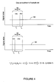
- Figure 4 illustrates one embodiment of the analysis of a sample set comprising adjacent long and short intervals
- Figure 5 illustrates another embodiment of the sample set comprising a short interval interposed between long intervals such that a short signal is obtained from the short interval and a long signal is obtained from the long-short-long intervals;
- Figure 6 illustrates another embodiment of the sample set including idle intervals interposed between integration intervals.
- Figure 7 illustrates an overlapping sampling method wherein portions of neighboring sample sets overlap to increase the number of sample sets.
- Figure 1A illustrates an exemplary schematic diagram for an analyzer 90 capable of sequence determination or fragment analysis for nucleic acid samples.
- the analyzer 90 may comprise one or more components or devices that are used for labeling and identification of the samples by performing automated sequence analysis.
- the various components of the analyzer 90 described in greater detail hereinbelow, may comprise separate components or a singular integrated system.
- the present teachings may further be applied to both automatic and semi-automatic sequence analysis systems as well as to methodologies wherein some of the sequence analysis operations are manually performed.
- the dynamic range enhancement methods may be applied to numerous different types of photo and signal detection methodologies and are not necessarily limited to CCD signal detection and resolution.
- the present teachings are described in various embodiments in the context of sequence analysis, these methods may be readily adapted to other devices/instrumentation and used for purposes other than sequence analysis.
- the present teachings may be applied to electronic telescopes and microscopes that utilize photo-detecting devices such as CCDs to improve the dynamic range and signal-to-noise ratio (SNR) of these instruments.
- SNR signal-to-noise ratio
- Photo-detectors in general convert incident photons to electrical signals, and may include, by way example, CCDs, photomultipliers, or semiconductor based devices such as photo-diodes.
- the exemplary sequence analyzer 90 may comprise a reaction component 92 wherein PCR amplification or cycle sequencing of the sample is performed. Using these amplification techniques, a label such as a fluorescent or radioactive dideoxy-nucleotide may be introduced into the sample resulting in the production of a number of fragments of varying sequence lengths. As is known in the art, one or more labels or dyes may be used during the amplification step to generate distinguishable fragment populations for each base to be subsequently identified. Following amplification, the fragments may then be subjected to a separation operation using a separation component 94. In one aspect the separation component 94 comprises a gel-based or capillary electrophoresis apparatus which separates the fragments into distinguishable populations.
- electrical current may be passed through the amplified sample fragments which have been loaded into a separation matrix (e.g. polyacrylamide or agarose gel).
- a separation matrix e.g. polyacrylamide or agarose gel.
- the application of electrical current results in the migration of the sample through the matrix.
- the labeled fragments are separated and passed through a detector 96 wherein resolution of the labeled fragments is performed.
- the detector 96 may identify various sizes or differential compositions for the fragments based on the presence of the incorporated label.
- fragment detection may be performed by generation of a detectable signal produced by a fluorescent label that is excited by a laser tuned to the label's absorption wavelength. Energy absorbed by the label results in a fluorescence emission that corresponds to a signal measured for each fragment. By keeping track of the order of fluorescent signal appearance along with the type of label incorporated into the fragment, the sequence of the sample can be discerned. A more detailed explanation of the sequencing process is provided in commonly assigned U.S. Patent No. 6,040,586 , entitled “Method and System for Velocity-Normalized Position-Based Scanning.”
- Figure 1B further illustrates exemplary components for the detector 96 which may be used to acquire the signal associated with a plurality of labeled fragments 100.
- the labeled fragments 100 may be resolved by measuring the quantity of fluorescence or emitted energy generated when the fragments 100 are subjected to an excitation source 114 of the appropriate wavelength and energy (e.g. a tuned laser).
- the energy emissions 120 produced by a label 116 associated with the fragments 100 may be detected using a charge-coupled device (CCD) 122 as the fragments 100 pass through a detection window 123 where a plurality of energy detecting elements 124 capture at least some of the emitted energy from the label 116.
- CCD charge-coupled device
- an electronic signal 125 is generated by the CCD 122 that is approximately proportional to the relative abundance of the fragments 100 passing through the detection window 123 at the time of energy capture and the order which the fragments 100 appear in the detection window 123 may be indicative of their relative length with respect to one another.
- a signal processor 126 is further configured to perform signal sampling operations to acquire the electronic signal generated by the CCD 122 in response to the fragments 100.
- the signal processor 126 is configured to perform these sampling operations in a predetermined manner by signal acquisition over selected intervals.
- the pattern or timing of signal acquisition is limited by software and/or hardware imposed restrictions which limit the flexibility in analysis of the signal. This may further result in a limited dynamic range of signal acquisition.
- the present teachings may aid in overcoming some sampling limitations and provide increased flexibility in signal analysis and resolution.
- One desirable feature provided by various embodiments of the present teachings is the ability to utilize existing signal information in such a manner so as to improve the dynamic range of the system thereby potentially increasing its functionality.
- the signal 125 outputted by the CCD 122 may vary significantly between sample fragments 100. This presents a potential problem in conventional systems as the signal 125 may exceed the dynamic range of the signal processor 126 associated with the CCD 122 unless compensatory measures are taken.
- signals 125 may be acquired forming a signal distribution comprised of one or more signal intensity "peaks". Each peak may further be indicative of a detected fragment 100.
- the electropherogram 127 may further comprise a theoretical or experimental dynamic range limit 131 wherein peak intensities which exceed this limit 131 are subject to diminished accuracy in quantitation. This concept is exemplified by an exemplary peak 133 shown to exceed the dynamic range limit 131.
- the quantitation and sequence resolution information arising from the peak 133 may be compromised.
- the present teachings facilitate resolution of peak intensities which may exceed the normal signal processor tolerances and may establish a new dynamic range allowing for more accurate calculations to be performed with the available signal information.
- some of the information that may be determined through signal resolution and peak identification may include determination of the relative abundance or quantity of each fragment population. Evaluation of the signals may further be used to determine the sequence or composition of the sample using various known base sequence resolution techniques. It will further be appreciated by one of skill in the art that the exemplified signal distribution may represent one or more nucleic acid fragments for which the relative abundance of each fragment may be determined based, in part, upon the determination of the relative area associated with each peak. The present teachings may therefore be integrated into existing analysis approaches to facilitate peak evaluation and subsequent integration operations typically associated with sequence analysis.
- the analysis of the electropherogram 127 may be advantageously performed by the signal processor 126.
- the signal processor 126 may further be configured to execute on one or more processors.
- the signal processor's components may include, but are not limited to, software or hardware components, modules such as software modules, object-oriented software components, class components and task components, processes methods, functions, attributes, procedures, subroutines, segments of program code, drivers, firmware, microcode, circuitry, data, databases, data structures, tables, arrays, and variables.
- the signal processor 126 may output a processed signal or analysis results to other devices or instrumentation where further processing may take place.
- FIG. 2 illustrates one aspect of signal processing that may be implemented by the signal processor 126 described above in reference to Figure 1A-C .
- a software controlled sampling method comprises an alternating series of having a long sample 134 and a short sample 136. These samples 134 reflect a time period where information is actively acquired from the CCD 122.
- an idle time interval (also referred to as "dead time") exists between adjacent sampling intervals.
- an idle interval may be is interposed temporally between the long and short samples.
- the idle interval may be substantially negligible when compared to the short or long sampling intervals.
- the idle interval may be significant and account for an appreciable amount of the sampling time.
- identification of the idle time may be useful in improving the dynamic range of signal detection.
- the long sample 134 may represent an integration of the signal 125 during a time interval of T L .
- Such an integration of the signal 125 from the CCD 122 may result in a measured signal L that includes an actual signal A L and an integration independent component C (offset).
- the integration independent component C includes, but is not limited to, an on-chip amplifier bias and spurious charge associated with the CCD 122.
- the short sample 136 may represent an integration of the signal 125 during a time interval of T S .
- Such an integration of the signal 125 from the CCD 122 results in a measured signal S that may include an actual signal A S and the offset C .
- the offset C may be determined with Equation 4.
- the resulting offset C may be subtracted from the measured signals L and S to yield the actual signals A L and A S , respectively.
- a sample set comprises at least one long sample 134 and one short sample 136 that is temporally adjacent to the at least one long sample 134.
- various combinations of the long and short samples may be formed to obtain such a sample set.
- the measured signals L and S may be obtained by directing the CCD signal 125 into a charge integrating analog to digital converter (ADC) and integrating for T L and T S respectively.
- the integrated signal may depend on the number of photo-electrons ( N ) generated by the CCD 122 where N obeys Poisson statistics. As is understood, relative intrinsic error associated with Poisson statistics may be expressed as 1 / N . This relationship indicates that it is generally preferable for the integrated signal to be as large as possible within the dynamic range of the ADC. Thus in one aspect, long and short measurements that make up the sample set may be selectively scaled.
- the long measurement is used for signal analysis if the long signal L is within the dynamic range of the ADC, since long measurements generally yield a signal with a higher signal-to-noise ratio. If the long signal L for a given sample set exceeds the dynamic range, then the short sigal S may be scaled in a manner described below in order to extrapolate or approximate what the long signal L value might be. In this instance, the scaled value of the short signal S is then used for subsequent signal analysis.
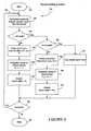
- FIG. 3 illustrates a signal scaling process 140 that may be used to implement the aforementioned selective scaling approach.
- the process commences in a start state 142 and enters a loop 148 described below.
- the loop 148 cycles through an array or data structure that has been loaded with values for L and S acquired during CCD analysis of the sample. Alternatively, the loop 148 may progress in real time as analysis takes place.
- state 144 of the loop 148 measured integral values of L and S of a sample set are determined.
- a decision state 146 that follows may be used to determine whether the value of L is off scale or exceeds the dynamic range of the instrumentation. In the instance where the dynamic range is not exceeded, L may be used for subsequent analysis as previously described.
- value of the offset C may be determined (according to Equation 4) from the measured values of L and S , along with the signal-specific value of the proportionality parameter K .
- the offset C may be subtracted from the measured value of L to yield the actual signal A L .
- the scaled signal value that is to be used for subsequent analysis may be assigned the unscaled value of the actual signal A L .
- the process 140 determines in a decision state 156 whether the loop 148 should continue. If the loop 148 continues, then the process proceeds back to state 144 to initiate another cycle. If the loop 148 is complete, then the process terminates at a stop state 160.
- state 146 when the determination is made that the measured signal L exceeds the scaling limit, then it may be observed that the usefulness of the measured signal L is potentially limited, and thus the measured signal S may be processed and scaled so as to extrapolate as to where the actual long signal A L might be.
- another decision state 162 may be entered that determines if the measured signal S itself exceeds the dynamic range. In one aspect, if the measured signal is within the dynamic range, then it may be processed and scaled in the manner described below.
- a value for the offset C is determined.
- the measured signal L may not be used for the current sample set since the value of C determined by using Equation 4 may produce an off scale result.
- the value of C may be obtained from the previous or a recent sample set. Offset determination in this manner is desirable as in many CCD systems, the offset C does not fluctuate substantially. This is typically true if the operating conditions, such as temperature, are controlled.
- the approximation method in state 164 is one manner for determining the value of C .
- the offset C may be subtracted from the measured signal S to generate the actual signal A S .
- the actual signal A S is scaled by a factor of K and may be assigned as the scaled signal value that is to be used for subsequent analysis.
- One method for determining the parameter K is described below.
- the process 140 then proceeds to the previously described decision state 156 to determine if the loop 148 should continue.
- both measured signals L and S may be considered off scale with regard to the dynamic range.
- the process may identify each signal as having limited usefulness for the current sample set.
- such off-scale measured signals may be "capped” or flagged in state 172 by a selected value so as to be easily recognizable during subsequent analysis.
- M is the upper limit value of the dynamic range
- M the capped signal value
- Such easy identification of off-scale signals may then be dealt with in an appropriate manner during the subsequent analysis.
- the sample set may comprise different combinations of the alternating short and long samples.
- Figures 4-6 illustrate various embodiments of the sample set and signal distribution characteristics.
- the measured signals L and S may be obtained in a sample set specific manner depending upon the characteristics of sampling.
- each sample set may be suited for a particular signal type resolution as described below.
- the proportionality parameter K may be associated with a selected sample set to yield an operationally useful value in processing the signal information.
- determination of the sample set specific L , S , and K allows for determination of the scaled signal value described above in a generalized process in reference to Figure 3 .
- a sample set 182 comprises a combination of a long sample and an adjacent short sample.
- a sample set 186 may comprise a short sample followed by a long sample.
- Sample sets 182, 186 may be used when signals 180, 184, respectively, are either generally flat or change relatively slowly during the time interval associated with the sample sets. For such a signal, the integrated values of the actual signals A L and A S are directly proportional to their respective integration times T L and T S .
- T L / T S A L / A S , where the ratio A L / A S is the definition of the proportionality parameter K (Equation 3).
- the offset C can be determined according to Equation 5b, thereby allowing the scaled signal value to be determined in a manner described above.
- a sample set 192 comprises a sequence of long-short-long sampling time intervals T 1 , T 2 , and T 3 , with corresponding measured signals A 1 , A 2 , and A 3 .
- n is a constant value.
- the offset C can be determined according to Equation 6b, thereby allowing the scaled signal value to be determined in a manner described above.
- sample set 192 illustrated in Figure 5 may be used when the CCD signal is approximately linear, at least during the interval encompassed by the sample set. In the instance where the CCD signal is not substantially linear, a systematic variance may be generated, however, this variance may be within the acceptable range for a given measurement and analysis.
- each of the long intervals T 1 and T 3 is selected to be approximately half of a "standard" non-segmented integration time.
- the short interval T 2 is typically substantially smaller than T 1 or T 3 , and is selected to achieve, by methods disclosed herein, a desired dynamic range.
- the duration of the long and short intervals may be determined by the existing hardware used in the sequence analysis system. These durations may be modifiable or fixed depending on the type of instrument used.
- One advantage to the present teachings is that the disclosed methods may be applied to signal information generated by most conventional systems in its raw form without necessitating hardware modifications to improve the dynamic range.
- Figure 6 illustrates another sample set 212 that accounts for the idle time intervals.
- the sample set 212 is similar to the sample set 192 of Figure 5 , with the exception that an idle time interval may be interposed between two adjacent sampling intervals.
- the sample set 212 comprises a sequence of time intervals T 1 to T 5 , wherein TI corresponds to a first long sample with measured signal A 1 , T 2 corresponds to a first idle time interval, T 3 corresponds to a short sample with measured signal A 3 , T 4 corresponds to a second idle time interval, and T 5 corresponds to a second long sample with measured signal A 5 .
- the offset C can be determined according to Equation 7b, thereby allowing the scaled signal value to be determined in a manner similar to that described above.
- the sample set 212 illustrated in Figure 6 may be used when the CCD signal 125 is approximately linear, at least during the interval encompassed by the sample set. While the CCD signal 125 may not be substantially linear thereby generating a systematic variance, such variances may be within the acceptable range for a given measurement and analysis.
- the first and second idle time intervals T 2 and T 4 are desirably similar in order to preserve the symmetry of the long and short samples, and thus facilitate establishing the common median value 214.
- the idle interval may be a function of the CCD 122 and its associated signal processing devices, with a range of approximately 1 - 10 ms.
- the idle intervals T 2 and T 4 are selected to be as short as possible, usually limited by camera hardware and/or control firmware.
- the long intervals T 1 , T 5 , and the short interval T 3 therebetween may be selected in a similar manner as that described above in reference to Figure 5 .
- a sampling method may include overlapping of the sample sets in a manner described below.
- Figure 7 illustrates a series of alternating long and short integration intervals, with idle intervals interposed therebetween. It will be appreciated that while the sampling method of Figure 7 is described in context of having the idle interval, the sampling method is equally applicable to situations where the idle interval is either relatively small or substantially negligible.
- an overlapping sampling method 240 comprises a plurality of sample sets with each sample set having the short interval interposed between the two long intervals. Such a sample set is described above in reference to Figure 6 .
- An exemplary segment of CCD signal sampling comprises a sequence of long interval 242, short interval 244, long interval 246, short interval 250, long interval 252, and short interval 254.
- a first exemplary sample set 260 comprises a short measured signal S1 obtained by integrating during the short interval 244 and a long measured signal L1 obtained by integrating during the intervals 242, 244, and 246.
- a second exemplary sample set 262 comprises a short measured signal S2 obtained by integrating during the short interval 250 and a long measured signal L2 obtained by integrating during the intervals 246, 250, and 252.
- the first and second sample sets 260 and 262 overlap in the long interval 246.
- Such an overlapping allows the number of samples sets (data points) to be increased for a given measurement pass. If the measurement pass comprises a total time interval having N non-overlapping sequential sample sets, the overlapping allows the number of sample sets to increase to approximately 2N.
- the various long-short-long integration methods described above in reference to Figures 5-7 can be adapted to reduce the effects of noise (thereby increasing the signal to noise ratio) associated with the CCD camera.
- the short integration time interval is interposed between two long integration time intervals, and the measured long signal is the sum of the integrated values during the long-short-long intervals ( lsl method).
- the signal to noise ratio (SNR) of the measurement can be increased.
- the noise ⁇ refers to an intrinsic uncertainty introduced during the process of quantifying the signal on the CCD and, in most cases, may be estimated as a square root of quadratures of it's main components - read noise ⁇ R and shot noise ⁇ S .
- each of the two long intervals is approximately n times as long as the short interval.
- a lsl 2 ⁇ n + 1 2 ⁇ n ⁇ A ll
- a lsl is the actual signal for the lsl method
- a ll is the actual signal for the ll method.
- SNR ll lSNR lsl 1.12, indicating an approximately 12% increase in the signal to noise ratio.
- the ratio SNR ll / SNR lsl can be increased further by selecting a different values n, A L , ⁇ R, or any combination thereof.
Landscapes
- Engineering & Computer Science (AREA)
- Multimedia (AREA)
- Signal Processing (AREA)
- Physics & Mathematics (AREA)
- Health & Medical Sciences (AREA)
- General Physics & Mathematics (AREA)
- Pathology (AREA)
- Immunology (AREA)
- Life Sciences & Earth Sciences (AREA)
- Chemical & Material Sciences (AREA)
- Analytical Chemistry (AREA)
- Biochemistry (AREA)
- General Health & Medical Sciences (AREA)
- Spectroscopy & Molecular Physics (AREA)
- Mathematical Physics (AREA)
- Theoretical Computer Science (AREA)
- Power Engineering (AREA)
- Nuclear Medicine, Radiotherapy & Molecular Imaging (AREA)
- Investigating, Analyzing Materials By Fluorescence Or Luminescence (AREA)
- Reduction Or Emphasis Of Bandwidth Of Signals (AREA)
- Transforming Light Signals Into Electric Signals (AREA)
- Measurement Of The Respiration, Hearing Ability, Form, And Blood Characteristics Of Living Organisms (AREA)
- Investigating Or Analysing Materials By Optical Means (AREA)
Claims (18)
- Procédé pour mettre à l'échelle un signal généré par un processeur de signaux de photodétecteur, le procédé comportant les étapes consistant à :a) déterminer une première valeur de signal L et une seconde valeur de signal S pour un premier ensemble d'échantillons comportant un premier intervalle comportant deux longs intervalles de temps d'intégration et un second intervalle comportant un court intervalle de temps d'intégration, la première valeur de signal correspondant à un signal acquis au cours du premier intervalle et la seconde valeur de signal correspondant à un signal acquis au cours du second intervalle, la seconde valeur de signal étant inférieure à la première valeur de signal, et la première valeur de signal et la seconde valeur de signal pouvant dépasser une plage spécifiée ;b) déterminer un paramètre de proportionnalité K entre la première valeur de signal et la seconde valeur de signal sur la base du premier intervalle et du second intervalle ;c) déterminer une composante de décalage à partir de valeurs en cours de L et S pour ledit ensemble d'échantillons lorsque la première valeur de signal est dans la plage spécifiée et ajuster la première valeur de signal afin de prendre en compte la composante de décalage, dans lequel la composante de décalage est un signal indépendant d'une intégration C ;d) ajuster la seconde valeur de signal afin de prendre en compte une composante de décalage déterminée précédemment, et la mettre à l'échelle pour approximer ce que la première valeur de signal sera lorsque seule ladite première valeur de signal est au-delà de la plage spécifiée ; ete) répéter les étapes a), c) et d) avec un second ensemble d'échantillons avoisinant comportant un premier intervalle correspondant incluant deux longs intervalles de temps d'intégration et un second intervalle correspondant comportant un court intervalle de temps d'intégration ; le premier ensemble d'échantillons chevauchant le second ensemble d'échantillons par au moins l'un des deux longs intervalles de temps d'intégration.
- Procédé selon la revendication 1, dans lequel la plage spécifiée comporte une plage dynamique d'une composante du processeur de signaux de photodétecteur.
- Procédé selon la revendication 2, dans lequel la composante du processeur de signaux de photodétecteur comporte un convertisseur analogique - numérique.
- Procédé selon la revendication 1, comportant en outre l'étape consistant à affecter une valeur de signal mise à l'échelle pour le premier ensemble d'échantillons sur la base de la première valeur de signal et de la seconde valeur de signal.
- Procédé selon la revendication 1, dans lequel la composante de décalage est soustraite de la première valeur de signal et de la seconde valeur de signal.
- Procédé selon la revendication 1, dans lequel le décalage C est déterminé selon l'équation C = S - (L - S) / (K - 1).
- Procédé selon la revendication 4, dans lequel l'étape d'affectation de la valeur de signal mise à l'échelle pour le premier ensemble d'échantillon comporte les étapes consistant à :sélectionner une première valeur de signal ajustée décalée comme valeur de signal mise à l'échelle lorsque la première valeur de signal se situe dans la plage spécifiée ;affecter la seconde valeur de signal ajustée décalée mise à l'échelle comme la valeur de signal mise à l'échelle pour le premier ensemble d'échantillons lorsque la première valeur de signal dépasse la plage spécifiée et que la seconde valeur de signal non mise à l'échelle se situe dans la plage spécifiée ; etaffecter une valeur par défaut à la valeur de signal mise à l'échelle pour le premier ensemble d'échantillons obtenu à partir d'un ensemble d'échantillons précédent lorsque les première et seconde valeurs de signal dépassent la plage spécifiée.
- Procédé selon la revendication 7, dans lequel la seconde valeur de signal mise à l'échelle est obtenue en multipliant la seconde valeur de signal ajustée décalée par le paramètre de proportionnalité K.
- Procédé selon la revendication 8, dans lequel les longs intervalles de temps d'intégration du premier intervalle sont respectivement plus longs que le court intervalle de temps d'intégration du second intervalle par un facteur d'approximativement n, de sorte que pour un signal de faible variation, le paramètre de proportionnalité K est approximativement égal à n et de sorte que le décalage C est déterminé selon l'équation C = S - (L - S) / (n - 1).
- Procédé selon la revendication 8, dans lequel le premier intervalle inclut en outre le court intervalle de temps d'intégration du second intervalle interposé entre les longs intervalles de temps d'intégration de cela, de sorte que les premier et second intervalles partagent une valeur temporelle médiane commune approximativement centrée autour du court intervalle de temps d'intégration.
- Procédé selon la revendication 8, dans lequel les longs intervalles de temps d'intégration sont respectivement plus longs que le court intervalle de temps d'intégration par un facteur d'approximativement n, de sorte que pour un signal approximativement linéaire, le paramètre de proportionnalité K est approximativement égal à 2n + 1 et de sorte que le décalage C est déterminé selon l'équation C = S - (L - S) / (2n).
- Procédé selon la revendication 10, dans lequel le premier intervalle inclut en outre deux intervalles de temps au repos respectivement interposés entre l'un des longs intervalles de temps d'intégration et le court intervalle de temps d'intégration de cela, dans lequel les intervalles de temps au repos correspondent à des temps morts.
- Procédé selon la revendication 12, dans lequel les premier et second intervalles partagent une valeur temporelle médiane commune approximativement centrée autour du court intervalle de temps d'intégration.
- Procédé selon la revendication 13, dans lequel les longs intervalles de temps d'intégration sont respectivement plus longs que le court intervalle de temps d'intégration par un facteur d'approximativement n, de sorte que pour un signal approximativement linéaire, le paramètre de proportionnalité K est approximativement égal à 2n + 1 et de sorte que le décalage C est déterminé selon l'équation C = S - (L - S) / (2n).
- Procédé selon la revendication 8, dans lequel le court intervalle de temps d'intégration du second intervalle est interposé entre les longs intervalles de temps d'intégration du premier intervalle, de sorte que les premier et second intervalles partagent une valeur temporelle médiane commune approximativement centrée autour du court intervalle de temps d'intégration du second signal.
- Procédé selon la revendication 15, dans lequel les longs intervalles de temps d'intégration sont respectivement plus longs que le court intervalle de temps d'intégration par un facteur d'approximativement n, de sorte que pour un signal approximativement linéaire, le paramètre de proportionnalité K est approximativement égal à 2n et de sorte que le décalage C est déterminé selon l'équation C = S - (L - S) / (2n - 1).
- Procédé selon la revendication 16, dans lequel le rapport signal sur bruit de la première valeur de signal est amélioré en excluant le bruit associé au photodétecteur au cours du court intervalle de temps d'intégration dans lequel le bruit inclut un bruit de grenaille et un bruit de lecture.
- Procédé selon la revendication 1, dans lequel le signal de photodétecteur provient d'un dispositif à couplage de charges (CCD), d'un photomultiplicateur, ou d'un dispositif à base de semi-conducteurs.
Priority Applications (1)
| Application Number | Priority Date | Filing Date | Title |
|---|---|---|---|
| EP07024650A EP1903331A1 (fr) | 2002-10-15 | 2003-10-08 | Système et procédés pour l'extension de plage dynamique utilisant l'échantillonnage de temps d'intégration de longueur variable |
Applications Claiming Priority (3)
| Application Number | Priority Date | Filing Date | Title |
|---|---|---|---|
| US10/271,477 US6894264B2 (en) | 2002-10-15 | 2002-10-15 | System and methods for dynamic range extension using variable length integration time sampling |
| US271477 | 2002-10-15 | ||
| PCT/US2003/032081 WO2004036196A1 (fr) | 2002-10-15 | 2003-10-08 | Systeme et procedes d'extension de gamme dynamique au moyen d'un echantillonnage temporel par integration a longueur variable |
Related Child Applications (1)
| Application Number | Title | Priority Date | Filing Date |
|---|---|---|---|
| EP07024650A Division EP1903331A1 (fr) | 2002-10-15 | 2003-10-08 | Système et procédés pour l'extension de plage dynamique utilisant l'échantillonnage de temps d'intégration de longueur variable |
Publications (2)
| Publication Number | Publication Date |
|---|---|
| EP1552279A1 EP1552279A1 (fr) | 2005-07-13 |
| EP1552279B1 true EP1552279B1 (fr) | 2008-07-23 |
Family
ID=32069158
Family Applications (2)
| Application Number | Title | Priority Date | Filing Date |
|---|---|---|---|
| EP03770710A Expired - Lifetime EP1552279B1 (fr) | 2002-10-15 | 2003-10-08 | Systeme et procedes d'extension de gamme dynamique au moyen d'un echantillonnage temporel par integration a longueur variable |
| EP07024650A Withdrawn EP1903331A1 (fr) | 2002-10-15 | 2003-10-08 | Système et procédés pour l'extension de plage dynamique utilisant l'échantillonnage de temps d'intégration de longueur variable |
Family Applications After (1)
| Application Number | Title | Priority Date | Filing Date |
|---|---|---|---|
| EP07024650A Withdrawn EP1903331A1 (fr) | 2002-10-15 | 2003-10-08 | Système et procédés pour l'extension de plage dynamique utilisant l'échantillonnage de temps d'intégration de longueur variable |
Country Status (8)
| Country | Link |
|---|---|
| US (4) | US6894264B2 (fr) |
| EP (2) | EP1552279B1 (fr) |
| JP (1) | JP4823522B2 (fr) |
| AT (1) | ATE402406T1 (fr) |
| AU (1) | AU2003279217A1 (fr) |
| CA (1) | CA2502881A1 (fr) |
| DE (1) | DE60322409D1 (fr) |
| WO (1) | WO2004036196A1 (fr) |
Families Citing this family (14)
| Publication number | Priority date | Publication date | Assignee | Title |
|---|---|---|---|---|
| US6894264B2 (en) * | 2002-10-15 | 2005-05-17 | Applera Corporation | System and methods for dynamic range extension using variable length integration time sampling |
| US20050059017A1 (en) * | 2003-09-11 | 2005-03-17 | Oldham Mark F. | System and method for extending dynamic range of a detector |
| CN101237902B (zh) | 2005-06-06 | 2012-02-29 | 雷斯梅德有限公司 | 面罩系统 |
| US7227128B2 (en) * | 2005-06-30 | 2007-06-05 | Applera Corporation | System and methods for improving signal/noise ratio for signal detectors |
| US20070043510A1 (en) * | 2005-08-19 | 2007-02-22 | Beckman Coulter, Inc. | Assay system |
| US9077917B2 (en) | 2011-06-09 | 2015-07-07 | Apple Inc. | Image sensor having HDR capture capability |
| MX2014005191A (es) * | 2011-11-03 | 2014-05-28 | Koninkl Philips Nv | Dispositivo de interconexion modular para un paciente con montaje de camara y almohadillas nasales. |
| CA2804843C (fr) * | 2012-02-06 | 2021-02-02 | Ortho-Clinical Diagnostics, Inc. | Fenetres temporelles multiples permettant d'etendre la plage dans un dosage |
| US10690591B2 (en) | 2015-09-18 | 2020-06-23 | Apple Inc. | Measurement time distribution in referencing schemes |
| WO2017146972A1 (fr) * | 2016-02-22 | 2017-08-31 | Dolby Laboratories Licensing Corporation | Appareil et procédé de codage d'un contenu à cadence élevée en vidéo à fréquence de trame standard en utilisant un entrelacement temporel |
| US10991281B2 (en) | 2016-02-22 | 2021-04-27 | Dolby Laboratories Licensing Corporation | Apparatus and method for encoding high frame rate content in standard frame rate video using temporal interlacing |
| WO2017184423A1 (fr) | 2016-04-21 | 2017-10-26 | Bribbla Dynamics Llc | Multiplexage et codage servant à une commutation de référence |
| DE102016214469A1 (de) * | 2016-08-04 | 2018-02-08 | Schaeffler Technologies AG & Co. KG | Drehmomentübertragungseinrichtung |
| JP7651705B2 (ja) * | 2021-07-27 | 2025-03-26 | 株式会社日立ハイテク | マルチキャピラリ電気泳動装置 |
Family Cites Families (14)
| Publication number | Priority date | Publication date | Assignee | Title |
|---|---|---|---|---|
| JPS51107181A (en) * | 1975-03-18 | 1976-09-22 | Canon Kk | Sotsukoryohenkanhoshiki |
| US4538178A (en) * | 1983-06-24 | 1985-08-27 | Rca Corporation | Digital signal peaking apparatus with controllable peaking level |
| JPH04170175A (ja) * | 1990-11-02 | 1992-06-17 | Canon Inc | 固体撮像素子の駆動装置 |
| US5200623A (en) * | 1991-12-04 | 1993-04-06 | Grumman Aerospace Corp. | Dual integration circuit |
| JPH06315068A (ja) * | 1993-04-28 | 1994-11-08 | Xerox Corp | 短期および長期の積分周期を有するラスタ入力スキャナ |
| US6014213A (en) * | 1994-12-12 | 2000-01-11 | Visible Genetics Inc. | High dynamic range apparatus for separation and detection of polynucleotide fragments |
| DE69628187D1 (de) * | 1995-11-07 | 2003-06-18 | California Inst Of Techn | Bildsensor mit linearem ausgang mit grossem dynamikbereich |
| US6369737B1 (en) * | 1997-10-30 | 2002-04-09 | The Board Of Trustees Of The Leland Stanford Junior University | Method and apparatus for converting a low dynamic range analog signal to a large dynamic range floating-point digital representation |
| NZ332626A (en) * | 1997-11-21 | 2000-04-28 | Matsushita Electric Industrial Co Ltd | Expansion of dynamic range for video camera |
| US6008486A (en) * | 1997-12-31 | 1999-12-28 | Gentex Corporation | Wide dynamic range optical sensor |
| US6040586A (en) | 1998-05-05 | 2000-03-21 | The Perkin-Elmer Corporation | Method and system for velocity-normalized position-based scanning |
| JP2002528970A (ja) * | 1998-10-19 | 2002-09-03 | ベン−グリオン ユニバーシィティー オブ ザ ネゲブ | ダイナミック・レンジを適応的に実時間で拡張する方法を使用する光学撮像装置 |
| DE10110108A1 (de) | 2001-03-02 | 2002-09-19 | Reimar Lenz | Digitalkamera mit CMOS-Bildsensor verbesserter Dynamik und Verfahren zum Ansteuern eines CMOS-Bildsensors |
| US6894264B2 (en) * | 2002-10-15 | 2005-05-17 | Applera Corporation | System and methods for dynamic range extension using variable length integration time sampling |
-
2002
- 2002-10-15 US US10/271,477 patent/US6894264B2/en not_active Expired - Lifetime
-
2003
- 2003-10-08 DE DE60322409T patent/DE60322409D1/de not_active Expired - Lifetime
- 2003-10-08 EP EP03770710A patent/EP1552279B1/fr not_active Expired - Lifetime
- 2003-10-08 AT AT03770710T patent/ATE402406T1/de not_active IP Right Cessation
- 2003-10-08 CA CA002502881A patent/CA2502881A1/fr not_active Abandoned
- 2003-10-08 WO PCT/US2003/032081 patent/WO2004036196A1/fr not_active Ceased
- 2003-10-08 JP JP2004544835A patent/JP4823522B2/ja not_active Expired - Fee Related
- 2003-10-08 EP EP07024650A patent/EP1903331A1/fr not_active Withdrawn
- 2003-10-08 AU AU2003279217A patent/AU2003279217A1/en not_active Abandoned
-
2005
- 2005-02-17 US US11/059,740 patent/US7067791B2/en not_active Expired - Lifetime
-
2006
- 2006-06-26 US US11/426,514 patent/US7423251B2/en not_active Expired - Lifetime
- 2006-12-29 US US11/618,501 patent/US7423255B2/en not_active Expired - Lifetime
Also Published As
| Publication number | Publication date |
|---|---|
| AU2003279217A1 (en) | 2004-05-04 |
| JP4823522B2 (ja) | 2011-11-24 |
| EP1903331A1 (fr) | 2008-03-26 |
| JP2006503288A (ja) | 2006-01-26 |
| US20070139531A1 (en) | 2007-06-21 |
| US7423251B2 (en) | 2008-09-09 |
| US20040069928A1 (en) | 2004-04-15 |
| US20070145243A1 (en) | 2007-06-28 |
| ATE402406T1 (de) | 2008-08-15 |
| EP1552279A1 (fr) | 2005-07-13 |
| US7423255B2 (en) | 2008-09-09 |
| DE60322409D1 (de) | 2008-09-04 |
| US20050145780A1 (en) | 2005-07-07 |
| US6894264B2 (en) | 2005-05-17 |
| CA2502881A1 (fr) | 2004-04-29 |
| US7067791B2 (en) | 2006-06-27 |
| WO2004036196A1 (fr) | 2004-04-29 |
Similar Documents
| Publication | Publication Date | Title |
|---|---|---|
| EP1552279B1 (fr) | Systeme et procedes d'extension de gamme dynamique au moyen d'un echantillonnage temporel par integration a longueur variable | |
| US7473891B2 (en) | System and methods for improving signal/noise ratio for signal detectors | |
| US7233393B2 (en) | Signal noise reduction for imaging in biological analysis | |
| TWI910848B (zh) | 分光測定裝置及分光測定方法 | |
| EP2034716A2 (fr) | Procédé pour déterminer le gain à l'aide de signaux de sortie | |
| US20080240529A1 (en) | Methods for Improving the Perfomance of a Detector | |
| USRE44253E1 (en) | Self-scanned photodiode array with selectively-skipped pixels |
Legal Events
| Date | Code | Title | Description |
|---|---|---|---|
| PUAI | Public reference made under article 153(3) epc to a published international application that has entered the european phase |
Free format text: ORIGINAL CODE: 0009012 |
|
| 17P | Request for examination filed |
Effective date: 20050331 |
|
| AK | Designated contracting states |
Kind code of ref document: A1 Designated state(s): AT BE BG CH CY CZ DE DK EE ES FI FR GB GR HU IE IT LI LU MC NL PT RO SE SI SK TR |
|
| AX | Request for extension of the european patent |
Extension state: AL LT LV MK |
|
| DAX | Request for extension of the european patent (deleted) | ||
| 17Q | First examination report despatched |
Effective date: 20060719 |
|
| GRAP | Despatch of communication of intention to grant a patent |
Free format text: ORIGINAL CODE: EPIDOSNIGR1 |
|
| GRAS | Grant fee paid |
Free format text: ORIGINAL CODE: EPIDOSNIGR3 |
|
| GRAA | (expected) grant |
Free format text: ORIGINAL CODE: 0009210 |
|
| AK | Designated contracting states |
Kind code of ref document: B1 Designated state(s): AT BE BG CH CY CZ DE DK EE ES FI FR GB GR HU IE IT LI LU MC NL PT RO SE SI SK TR |
|
| REG | Reference to a national code |
Ref country code: GB Ref legal event code: FG4D |
|
| REG | Reference to a national code |
Ref country code: CH Ref legal event code: EP |
|
| REG | Reference to a national code |
Ref country code: IE Ref legal event code: FG4D |
|
| REF | Corresponds to: |
Ref document number: 60322409 Country of ref document: DE Date of ref document: 20080904 Kind code of ref document: P |
|
| NLV1 | Nl: lapsed or annulled due to failure to fulfill the requirements of art. 29p and 29m of the patents act | ||
| PG25 | Lapsed in a contracting state [announced via postgrant information from national office to epo] |
Ref country code: ES Free format text: LAPSE BECAUSE OF FAILURE TO SUBMIT A TRANSLATION OF THE DESCRIPTION OR TO PAY THE FEE WITHIN THE PRESCRIBED TIME-LIMIT Effective date: 20081103 Ref country code: PT Free format text: LAPSE BECAUSE OF FAILURE TO SUBMIT A TRANSLATION OF THE DESCRIPTION OR TO PAY THE FEE WITHIN THE PRESCRIBED TIME-LIMIT Effective date: 20081223 Ref country code: NL Free format text: LAPSE BECAUSE OF FAILURE TO SUBMIT A TRANSLATION OF THE DESCRIPTION OR TO PAY THE FEE WITHIN THE PRESCRIBED TIME-LIMIT Effective date: 20080723 |
|
| PG25 | Lapsed in a contracting state [announced via postgrant information from national office to epo] |
Ref country code: SI Free format text: LAPSE BECAUSE OF FAILURE TO SUBMIT A TRANSLATION OF THE DESCRIPTION OR TO PAY THE FEE WITHIN THE PRESCRIBED TIME-LIMIT Effective date: 20080723 Ref country code: AT Free format text: LAPSE BECAUSE OF FAILURE TO SUBMIT A TRANSLATION OF THE DESCRIPTION OR TO PAY THE FEE WITHIN THE PRESCRIBED TIME-LIMIT Effective date: 20080723 Ref country code: BG Free format text: LAPSE BECAUSE OF FAILURE TO SUBMIT A TRANSLATION OF THE DESCRIPTION OR TO PAY THE FEE WITHIN THE PRESCRIBED TIME-LIMIT Effective date: 20081023 Ref country code: FI Free format text: LAPSE BECAUSE OF FAILURE TO SUBMIT A TRANSLATION OF THE DESCRIPTION OR TO PAY THE FEE WITHIN THE PRESCRIBED TIME-LIMIT Effective date: 20080723 |
|
| PG25 | Lapsed in a contracting state [announced via postgrant information from national office to epo] |
Ref country code: BE Free format text: LAPSE BECAUSE OF FAILURE TO SUBMIT A TRANSLATION OF THE DESCRIPTION OR TO PAY THE FEE WITHIN THE PRESCRIBED TIME-LIMIT Effective date: 20080723 |
|
| PG25 | Lapsed in a contracting state [announced via postgrant information from national office to epo] |
Ref country code: DK Free format text: LAPSE BECAUSE OF FAILURE TO SUBMIT A TRANSLATION OF THE DESCRIPTION OR TO PAY THE FEE WITHIN THE PRESCRIBED TIME-LIMIT Effective date: 20080723 Ref country code: EE Free format text: LAPSE BECAUSE OF FAILURE TO SUBMIT A TRANSLATION OF THE DESCRIPTION OR TO PAY THE FEE WITHIN THE PRESCRIBED TIME-LIMIT Effective date: 20080723 |
|
| PG25 | Lapsed in a contracting state [announced via postgrant information from national office to epo] |
Ref country code: CZ Free format text: LAPSE BECAUSE OF FAILURE TO SUBMIT A TRANSLATION OF THE DESCRIPTION OR TO PAY THE FEE WITHIN THE PRESCRIBED TIME-LIMIT Effective date: 20080723 Ref country code: MC Free format text: LAPSE BECAUSE OF NON-PAYMENT OF DUE FEES Effective date: 20081031 Ref country code: RO Free format text: LAPSE BECAUSE OF FAILURE TO SUBMIT A TRANSLATION OF THE DESCRIPTION OR TO PAY THE FEE WITHIN THE PRESCRIBED TIME-LIMIT Effective date: 20080723 Ref country code: SK Free format text: LAPSE BECAUSE OF FAILURE TO SUBMIT A TRANSLATION OF THE DESCRIPTION OR TO PAY THE FEE WITHIN THE PRESCRIBED TIME-LIMIT Effective date: 20080723 |
|
| PLBE | No opposition filed within time limit |
Free format text: ORIGINAL CODE: 0009261 |
|
| REG | Reference to a national code |
Ref country code: CH Ref legal event code: PL |
|
| STAA | Information on the status of an ep patent application or granted ep patent |
Free format text: STATUS: NO OPPOSITION FILED WITHIN TIME LIMIT |
|
| REG | Reference to a national code |
Ref country code: GB Ref legal event code: 732E Free format text: REGISTERED BETWEEN 20090514 AND 20090520 |
|
| 26N | No opposition filed |
Effective date: 20090424 |
|
| PG25 | Lapsed in a contracting state [announced via postgrant information from national office to epo] |
Ref country code: IT Free format text: LAPSE BECAUSE OF FAILURE TO SUBMIT A TRANSLATION OF THE DESCRIPTION OR TO PAY THE FEE WITHIN THE PRESCRIBED TIME-LIMIT Effective date: 20080723 |
|
| PG25 | Lapsed in a contracting state [announced via postgrant information from national office to epo] |
Ref country code: LI Free format text: LAPSE BECAUSE OF NON-PAYMENT OF DUE FEES Effective date: 20081031 Ref country code: IE Free format text: LAPSE BECAUSE OF NON-PAYMENT OF DUE FEES Effective date: 20081008 Ref country code: CH Free format text: LAPSE BECAUSE OF NON-PAYMENT OF DUE FEES Effective date: 20081031 |
|
| PG25 | Lapsed in a contracting state [announced via postgrant information from national office to epo] |
Ref country code: SE Free format text: LAPSE BECAUSE OF FAILURE TO SUBMIT A TRANSLATION OF THE DESCRIPTION OR TO PAY THE FEE WITHIN THE PRESCRIBED TIME-LIMIT Effective date: 20081023 |
|
| REG | Reference to a national code |
Ref country code: GB Ref legal event code: 732E Free format text: REGISTERED BETWEEN 20100121 AND 20100127 |
|
| REG | Reference to a national code |
Ref country code: FR Ref legal event code: TP Ref country code: FR Ref legal event code: CD |
|
| PG25 | Lapsed in a contracting state [announced via postgrant information from national office to epo] |
Ref country code: CY Free format text: LAPSE BECAUSE OF FAILURE TO SUBMIT A TRANSLATION OF THE DESCRIPTION OR TO PAY THE FEE WITHIN THE PRESCRIBED TIME-LIMIT Effective date: 20080723 Ref country code: HU Free format text: LAPSE BECAUSE OF FAILURE TO SUBMIT A TRANSLATION OF THE DESCRIPTION OR TO PAY THE FEE WITHIN THE PRESCRIBED TIME-LIMIT Effective date: 20090124 Ref country code: LU Free format text: LAPSE BECAUSE OF NON-PAYMENT OF DUE FEES Effective date: 20081008 |
|
| PG25 | Lapsed in a contracting state [announced via postgrant information from national office to epo] |
Ref country code: TR Free format text: LAPSE BECAUSE OF FAILURE TO SUBMIT A TRANSLATION OF THE DESCRIPTION OR TO PAY THE FEE WITHIN THE PRESCRIBED TIME-LIMIT Effective date: 20080723 |
|
| PG25 | Lapsed in a contracting state [announced via postgrant information from national office to epo] |
Ref country code: GR Free format text: LAPSE BECAUSE OF FAILURE TO SUBMIT A TRANSLATION OF THE DESCRIPTION OR TO PAY THE FEE WITHIN THE PRESCRIBED TIME-LIMIT Effective date: 20081024 |
|
| REG | Reference to a national code |
Ref country code: FR Ref legal event code: PLFP Year of fee payment: 14 |
|
| REG | Reference to a national code |
Ref country code: FR Ref legal event code: PLFP Year of fee payment: 15 |
|
| REG | Reference to a national code |
Ref country code: FR Ref legal event code: PLFP Year of fee payment: 16 |
|
| PGFP | Annual fee paid to national office [announced via postgrant information from national office to epo] |
Ref country code: FR Payment date: 20221023 Year of fee payment: 20 |
|
| PGFP | Annual fee paid to national office [announced via postgrant information from national office to epo] |
Ref country code: GB Payment date: 20221027 Year of fee payment: 20 Ref country code: DE Payment date: 20220928 Year of fee payment: 20 |
|
| REG | Reference to a national code |
Ref country code: DE Ref legal event code: R071 Ref document number: 60322409 Country of ref document: DE |
|
| REG | Reference to a national code |
Ref country code: GB Ref legal event code: PE20 Expiry date: 20231007 |
|
| PG25 | Lapsed in a contracting state [announced via postgrant information from national office to epo] |
Ref country code: GB Free format text: LAPSE BECAUSE OF EXPIRATION OF PROTECTION Effective date: 20231007 |
|
| PG25 | Lapsed in a contracting state [announced via postgrant information from national office to epo] |
Ref country code: GB Free format text: LAPSE BECAUSE OF EXPIRATION OF PROTECTION Effective date: 20231007 |