EP1552405B1 - Effiziente gemeinsame detektion - Google Patents
Effiziente gemeinsame detektion Download PDFInfo
- Publication number
- EP1552405B1 EP1552405B1 EP03793067A EP03793067A EP1552405B1 EP 1552405 B1 EP1552405 B1 EP 1552405B1 EP 03793067 A EP03793067 A EP 03793067A EP 03793067 A EP03793067 A EP 03793067A EP 1552405 B1 EP1552405 B1 EP 1552405B1
- Authority
- EP
- European Patent Office
- Prior art keywords
- matrix
- block
- data signals
- version
- extended
- Prior art date
- Legal status (The legal status is an assumption and is not a legal conclusion. Google has not performed a legal analysis and makes no representation as to the accuracy of the status listed.)
- Expired - Lifetime
Links
- 238000001514 detection method Methods 0.000 title description 27
- 239000011159 matrix material Substances 0.000 claims abstract description 120
- 239000013598 vector Substances 0.000 claims abstract description 87
- 238000004891 communication Methods 0.000 claims abstract description 41
- 238000001228 spectrum Methods 0.000 claims abstract description 11
- 238000006467 substitution reaction Methods 0.000 claims description 25
- 238000000354 decomposition reaction Methods 0.000 claims description 22
- 238000005070 sampling Methods 0.000 claims description 22
- 238000000034 method Methods 0.000 claims description 15
- 108010003272 Hyaluronate lyase Proteins 0.000 claims description 4
- 238000005192 partition Methods 0.000 claims description 4
- 238000000638 solvent extraction Methods 0.000 claims 2
- 238000003775 Density Functional Theory Methods 0.000 description 37
- 238000013459 approach Methods 0.000 description 8
- 238000010586 diagram Methods 0.000 description 5
- 238000012549 training Methods 0.000 description 5
- 238000009795 derivation Methods 0.000 description 3
- 230000005540 biological transmission Effects 0.000 description 2
- 238000001914 filtration Methods 0.000 description 2
- 230000000052 comparative effect Effects 0.000 description 1
- 238000003780 insertion Methods 0.000 description 1
- 230000037431 insertion Effects 0.000 description 1
- 230000010363 phase shift Effects 0.000 description 1
- 238000012545 processing Methods 0.000 description 1
Images


Classifications
-
- H—ELECTRICITY
- H04—ELECTRIC COMMUNICATION TECHNIQUE
- H04B—TRANSMISSION
- H04B1/00—Details of transmission systems, not covered by a single one of groups H04B3/00 - H04B13/00; Details of transmission systems not characterised by the medium used for transmission
- H04B1/69—Spread spectrum techniques
- H04B1/707—Spread spectrum techniques using direct sequence modulation
- H04B1/7097—Interference-related aspects
- H04B1/7103—Interference-related aspects the interference being multiple access interference
- H04B1/7105—Joint detection techniques, e.g. linear detectors
- H04B1/71052—Joint detection techniques, e.g. linear detectors using decorrelation matrix
-
- H—ELECTRICITY
- H04—ELECTRIC COMMUNICATION TECHNIQUE
- H04B—TRANSMISSION
- H04B2201/00—Indexing scheme relating to details of transmission systems not covered by a single group of H04B3/00 - H04B13/00
- H04B2201/69—Orthogonal indexing scheme relating to spread spectrum techniques in general
- H04B2201/707—Orthogonal indexing scheme relating to spread spectrum techniques in general relating to direct sequence modulation
- H04B2201/70707—Efficiency-related aspects
Definitions
- FIG. 1 is an illustration of a wireless communication system 10.
- the communication system 10 has base stations 12 1 to 12 5 (12) which communicate with user equipments (UEs) 14 1 to 14 3 (14).
- UEs user equipments
- Each base station 12 has an associated operational area, where it communicates with UEs 14 in its operational area.
- TDD/CDMA frequency division duplex using code division multiple access
- TDD/CDMA time division duplex using code division multiple access
- FDD/CDMA frequency division duplex using code division multiple access
- TDD/CDMA time division duplex using code division multiple access
- multiple communications are sent over the same frequency spectrum. These communications are differentiated by their channelization codes.
- TDD/CDMA communication systems use repeating frames divided into timeslots for communication. A communication sent in such a system will have one or multiple associated codes and timeslots assigned to it.
- MUD multiuser detection
- BLE-JD block linear equalizer
- WO 02/089346 A1 which is a document under Article 54(3) of the European Patent Convention discloses a method for fast joint detection where a combined channel response matrix is produced for all transmitted signals.
- K data signals, or bursts are transmitted over a shared spectrum in a code division multiple access communication format.
- a combined signal is received and sampled over the shared spectrum, as a plurality of received vector versions.
- the combined signal includes the K transmitted data signals.
- a plurality of system matrices and an associated covariance matrix using codes and estimated impulse responses of the K data signals is produced. Each system matrix corresponds to a received vector version.
- the system and covariance matrices are extended and approximated as block circulant matrices.
- a diagonal matrix of each of the extended and approximated system and covariance matrices are determined by prime factor algorithm - fast Fourier transform (PFA-FFT) without division of the matrices.
- PFA-FFT prime factor algorithm - fast Fourier transform
- the received vector versions are extended.
- a product of the diagonal matrices and the extended received vector versions is taken.
- An inverse block discrete Fourier transform is performed by a PFA-FFT on a result of
- Figure 1 is a wireless communication system.
- Figure 2 is a simplified transmitter and an efficient joint detection receiver.
- Figure 3 is an illustration of a communication burst.
- Figures 4a and 4b are a flow chart of a preferred embodiment for efficient joint detection.
- Figure 5 is an illustration of a data burst indicating extended processing areas.
- Figure 6 is a block diagram of a preferred implementation of efficient joint detection.
- Figure 7 is a simplified receiver having multiple antennas.
- Figure 8 is a simplified receiver sampling the received signal using fractional sampling.
- Figure 9 is a simplified receiver having multiple antennas and using fractional sampling.
- Figure 10 is a block diagram of a preferred implementation of efficient joint detection for fractional sampling or receive diversity.
- Figure 2 illustrates a simplified transmitter 26 and receiver 28 using efficient joint detection in a TDD/CDMA communication system, although efficient joint detection is applicable to other systems, such as FDD/CDMA.
- a transmitter 26 is in each UE 14 and multiple transmitting circuits 26 sending multiple communications are in each base station 12.
- the joint detection receiver 28 may be at a base station 12, UEs 14 or both.
- the transmitter 26 sends data over a wireless radio channel 30.
- a data generator 32 in the transmitter 26 generates data to be communicated to the receiver 28.
- a modulation/spreading/training sequence insertion device 34 spreads the data with the appropriate code(s) and makes the spread reference data time-multiplexed with a midamble training sequence in the appropriate assigned time slot, producing a communication burst or bursts.
- a typical communication burst 16 has a midamble 20, a guard period 18 and two data fields 22, 24, as shown in Figure 3 .
- the midamble 20 separates the two data fields 22, 24 and the guard period 18 separates the communication bursts to allow for the difference in arrival times of bursts transmitted from different transmitters 26.
- the two data fields 22, 24 contain the communication burst's data.
- the communication burst(s) are modulated by a modulator 36 to radio frequency (RF).
- An antenna 38 radiates the RF signal through the wireless radio channel 30 to an antenna 40 of the receiver 28.
- the type of modulation used for the transmitted communication can be any of those known to those skilled in the art, such as quadrature phase shift keying (QPSK) or M-ary quadrature amplitude modulation (QAM).
- the antenna 40 of the receiver 28 receives various radio frequency signals.
- the received signals are demodulated by a demodulator 42 to produce a baseband signal.
- the baseband signal is sampled by a sampling device 43, such as one or multiple analog to digital converters, at the chip rate of the transmitted bursts.
- the samples are processed, such as by a channel estimation device 44 and an efficient joint detection device 46, in the time slot and with the appropriate codes assigned to the received bursts.
- the channel estimation device 44 uses the midamble training sequence component in the baseband samples to provide channel information, such as channel impulse responses.
- the channel information is used by the efficient joint detection device 46 to estimate the transmitted data of the received communication bursts as soft symbols.
- the efficient joint detection device 46 uses the channel information provided by the channel estimation device 44 and the known spreading codes used by the transmitter 26 to estimate the data of the desired received communication burst(s).
- the receiver 28 receives a total of K bursts that arrive simultaneously, within one observation interval.
- each data field of a time slot corresponds to one observation interval.
- FDD frequency division duplex
- the received signals are continuous, i.e., not in bursts.
- FDD systems divide the received signals into time segments prior to applying efficient joint detection.
- a code used for a k th burst is represented as c ( k ) .
- the K bursts may originate from K different transmitters or for multi-code transmissions, less than K different transmitters.
- Each data field of a communication burst has a predetermined number of transmitted symbols, Ns.
- Each symbol is transmitted using a predetermined number of chips, which is the spreading factor, Q .
- each data field has Ns x Q chips.
- the observation interval at the receiver is of length Q x Ns + W -1 chips.
- Equation 1 The symbol response vector b ( k ) as the convolution of the channel response vector h ( k ) with the corresponding spreading code c ( k ) is per Equation 1.
- b ⁇ k h ⁇ k ⁇ c ⁇ k o denotes the convolutional operator.
- the length of b ( k ) is SF + W -1.
- Equation 2 the system matrix A is defined as per Equation 2.
- the size of the matrix is ( N s ⁇ SF+ W - 1) ⁇ N s ⁇ K.
- A is a block Topleitz matrix.
- Block B is defmed as per Equation 3.
- B b ⁇ 1 b ⁇ 2 ⁇ b ⁇ K
- the received vector sampled at the chip rate can be represented by Equation 4.
- r ⁇ A d ⁇ + n ⁇
- the size of vector r is ( N s ⁇ SF + W -1) by 1. This size corresponds to the observation interval.
- Data vector d of size N s ⁇ K by 1 has the form of Equation 5.
- d ⁇ d ⁇ 1 T d ⁇ 2 T ⁇ d ⁇ N s T T
- the sub-vector d n of size K by 1 is composed of the n th symbol of each user and is defined as Equation 6.
- the vector n of size (N s ⁇ SF + W- 1) by 1 is the background noise vector and is assumed to be white.
- Equation 7 Determining d using an MMSE solution is per Equation 7.
- d ⁇ R - 1 A H ⁇ r ⁇ ( ⁇ ) H represents the hermetian function (complex conjugate transpose).
- the covariance matrix of the system matrix R for a preferred MMSE solution is per Equation 8.
- R R H ⁇ A + ⁇ 2 ⁇ I ⁇ 2 is the noise variance, typically obtained from the channel estimation device 44, and I is the identity matrix.
- Equation 7 Using block circulant approximation and block DFT using PFA-FFTs, d in Equation 7 can be determined per Equation 9.
- the derivation of the block diagonal matrices ⁇ and ⁇ A is described subsequently.
- Equation 9 can be solved using the LU decomposition and the forward and backward substitution of the main diagonal block of ⁇ .
- Equation 9 can be solved using Cholesky decomposition.
- FIG. 4 is a flowchart for a preferred method of determining the data vector d using fast joint detection.
- the system matrix A is determined using the estimated channel response vector h ( k ) and the spreading code c ( k ) for each burst, 48.
- R the covariance matrix of the system matrix, is formed, 49.
- the system matrix A and its covariance matrix R are extended block square matrices.
- the extended A is of size D ⁇ Q by D ⁇ K and the extended R is of size D ⁇ K by D ⁇ K , respectively.
- D is chosen as per Equation 10.
- Both extended matrices are approximated to block circulant matrices, A c and R c , 50.
- the received vector, r is extended to the vector r c of size D ⁇ SF x 1 by inserting zeros, 51.
- the block-diagonal matrix, ⁇ is determined by taking a block DFT using PFA-FFT of the first block column of R c , 52.
- ⁇ A i is the i th main diagonal block of size SF by K in ⁇ A and F ( r c ) (i) is the i th block of size Q x 1 in F ( r c ).
- ⁇ A is the block DFT using PFA-FFT of the first column of A c and F ( r c ) is the block DFT using PFA-FFT of the vector, r c .
- the estimated data vector, d is determined by a inverse block-DFT of F ( d ), 57.
- Equation 9 is a MMSE based solution
- fast joint detection can be applied to other approaches, such as a zero forcing approach as per Equation 11.
- the ⁇ 2 I term is deleted from Equation 8.
- the following is a derivation for the MMSE solution, although an analogous derivation can be used for a zero forcing solution.
- Equation 2 a block DFT using PFA-FFT approach taking advantage of the block-Toeplitz structure of A may be used as shown in Equation 2.
- Equation 2 a block DFT using PFA-FFT approach taking advantage of the block-Toeplitz structure of A may be used as shown in Equation 2.
- B we extend A to a block-square matrix of size D ⁇ Q x D ⁇ K, to use all of the chip symbols in the observation interval.
- the extended A is composed of D 2 blocks of size Q x K .
- the extended A is approximated to the block-circulant matrix A c .
- a c can be decomposed into three matrices per Equation 12.
- ⁇ denotes a kronecker product.
- I n is an identity matrix of size n x n
- f il 1 D ⁇ exp - j ⁇ 2 ⁇ ⁇ il D D is the length of the DFT and
- F H F I .
- I is an identity matrix of size D x D .
- the block diagonal matrix ⁇ A is of size D ⁇ Q ⁇ D ⁇ K and has the form per Equation 14.
- ⁇ A ⁇ A 1 0 ⁇ 0 0 ⁇ A 2 ⁇ 0 ⁇ ⁇ ⁇ ⁇ 0 0 ... ⁇ A D
- Each of its entries ⁇ A i , i 1, 2, ..., D , is a Q by K block per Equation 15.
- ⁇ A i ⁇ 1 , 1 A i ⁇ ⁇ ⁇ 1 , K A i ⁇ ⁇ ⁇ ⁇ ⁇ ⁇ Q , 1 A i ⁇ ⁇ ⁇ Q , K A i
- ⁇ A 1 T ⁇ A 2 T ⁇ A D T T F Q ⁇ A c : , 1 : K
- a c (:, 1: K ) denotes the first block column of A c . Namely, the first K columns of A c .
- F ( SF ) A c ( : , 1: K ) can be calculated by Q ⁇ K parallel non-block DFTs of length D, using PFA-FFTs.
- the received vector r Due to the extention of A , the received vector r is also extended by inserting zeros, becoming vector rc of size D ⁇ Q by 1.
- F ( A H r ) is approximated to F A c H ⁇ r ⁇ c . It can be written as Equation 17.
- F A c H ⁇ r ⁇ c F K H ⁇ ⁇ A H ⁇ F Q ⁇ r ⁇ c
- the covariance matrix R of size N s ⁇ K ⁇ N s ⁇ K has the block-square matrix form shown in Equation 18.
- R R 0 R 1 H ⁇ R L H ⁇ ⁇ ⁇ ⁇ 0 ⁇ 0 0 R 1 R 0 ⁇ ⁇ ⁇ ⁇ ⁇ ⁇ ⁇ ⁇ ⁇ ⁇ ⁇ R 1 ⁇ ⁇ ⁇ ⁇ ⁇ ⁇ ⁇ ⁇ ⁇ ⁇ ⁇ ⁇ ⁇ ⁇ ⁇ ⁇ ⁇ ⁇ ⁇ ⁇ ⁇ R L ⁇ ⁇ ⁇ ⁇ ⁇ ⁇ ⁇ ⁇ 0 R L ⁇ ⁇ ⁇ ⁇ ⁇ ⁇ ⁇ ⁇ ⁇ ⁇ 0 ⁇ R L ⁇ ⁇ ⁇ ⁇ ⁇ ⁇ ⁇ ⁇ ⁇ ⁇ ⁇ 0 ⁇ R L ⁇ ⁇ ⁇ ⁇ ⁇ ⁇ ⁇ ⁇ ⁇ ⁇ ⁇ 0 ⁇ R L ⁇ ⁇ ⁇ ⁇ ⁇ ⁇ ⁇
- R c R 0 R 1 H ⁇ R L H ⁇ ⁇ ⁇ ⁇ 0 ⁇ R 2 R 1 R 1 R 0 ⁇ ⁇ ⁇ ⁇ ⁇ ⁇ ⁇ ⁇ ⁇ R 1 ⁇ ⁇ ⁇ ⁇ ⁇ ⁇ ⁇ ⁇ R L ⁇ ⁇ ⁇ ⁇ ⁇ ⁇ ⁇ ⁇ ⁇ ⁇ ⁇ R L R L ⁇ ⁇ ⁇ ⁇ ⁇ ⁇ ⁇ ⁇ ⁇ ⁇ 0 R L ⁇ ⁇ ⁇ ⁇ ⁇ ⁇ ⁇ ⁇ ⁇ ⁇ 0 R L ⁇ ⁇ ⁇ ⁇ ⁇ ⁇ ⁇ ⁇ ⁇ ⁇ ⁇ 0 ⁇ R L ⁇ ⁇ ⁇ ⁇ ⁇ ⁇ ⁇ ⁇ ⁇ ⁇ ⁇ 0 ⁇ R L ⁇ ⁇ ⁇ ⁇ ⁇ ⁇ ⁇ ⁇ ⁇ ⁇ ⁇ ⁇ 0 ⁇ R L ⁇ ⁇ ⁇ ⁇ ⁇ ⁇ ⁇ ⁇ ⁇ ⁇
- the block circulant matrix R c is decomposed into three matrices per Equation 21.
- ⁇ denotes a Kronecker product.
- I K is an identity matrix of size K x K and F is a DFT matrix of size D x D as described in Equation 13.
- the block diagonal matrix ⁇ of size D ⁇ K by D ⁇ K has the form per Equation 22.
- ⁇ ⁇ 1 0 ⁇ 0 0 ⁇ 2 ⁇ 0 ⁇ ⁇ ⁇ ⁇ 0 0 ⁇ ⁇ D
- ⁇ i ⁇ 1 , 1 i ⁇ ⁇ ⁇ 1 , K i ⁇ ⁇ ⁇ ⁇ ⁇ K , 1 i ⁇ ⁇ ⁇ K , K i
- ⁇ 1 T ⁇ 2 T ⁇ ⁇ D T T F K ⁇ R c : , 1 : K , R c (:, 1: K ) denotes the first block column of R c . Namely, the first K columns of R c .
- F ( K ) R c (:, 1: K ) can be calculated by K 2 parallel non-block DFTs of length D , using PFA_FFTs.
- Equation 7 The estimated data vector, d , in Equation 7 is preferably approximated per Equation 24A.
- the block diagonal matrix ⁇ -1 is per Equation 24B.
- ⁇ - 1 ⁇ 1 - 1 0 ⁇ 0 0 ⁇ 2 - 1 ⁇ 0 ⁇ ⁇ ⁇ ⁇ 0 0 ⁇ ⁇ D - 1
- Equation 24A can be rewritten as Equation 25.
- Equation 27 Each block in Equation 27 is solved separately, per Equation 28.
- F ⁇ d ⁇ i ⁇ i - 1 ⁇ ⁇ A H ⁇ F ⁇ r ⁇ c i
- F ( d ) ( i ) is a K by 1 vector.
- ⁇ ( i ) is a K by K matrix, per Equation 22.
- ⁇ A i is an Q by K matrix, per Equation 14.
- F ( r c ) ( i ) is an Q by 1 vector and is composed of elements (1+( i -1) Q ) through ( i ⁇ Q ) of F ( r c ).
- Equation 28 is represented as, per Equation 31.
- U i ⁇ F d ⁇ i y ⁇ i
- d is determined for all blocks as per Equation 34.
- Figure 6 is a block diagram of a preferred implementation of efficient joint detection in a TDD/CDMA system.
- r Using the received vector, r , r c is formed by inserting zeros, then a block DFT 100 of r c is performed per Equation 26, to produce F ( r c ).
- the channel impulse responses for each transmitted burst, h ( k ) is determined by an estimate channel response block 102.
- the system matrix, A is determined by compute block matrix A block 104 per Equation 2.
- the system matrix A is extended by extend block 132, to use all received chips in the observation interval.
- the first block column of the block-circulant matrix A c is determined by selecting the first K columns of the extended A matrix by first block column block 114.
- ⁇ A is determined.
- the complex conjugate transpose of ⁇ A i , ⁇ A i H is determined by a transpose block 130.
- a multiplier 128 multiplies ⁇ A i H by F ( r c ) ( i ) .
- ⁇ ( i ) is decomposed using LU decomposition by a LU decomposition block 126, per Equation 30.
- F ( d ) ( i ) is determined.
- F ( d ) is found.
- d is estimated.
- FIGs 7, 8 and 9 are simplified diagrams of receivers applying efficient joint detection to multiple reception antennas and/or fractional (multiple chip rate) sampling.
- a receiver 28 with multiple reception antennas is shown in Figure 7 .
- Transmitted bursts are received by each antenna 40 1 to 40 m (40).
- Each antennas' version of the received bursts are reduced to baseband, such as by demodulators 42 1 to 42 m .
- the baseband signals for each antenna are sampled by sampling devices 43 1 to 43 m to produce a received vector, r 1 to r m , for each antenna 40.
- the samples corresponding to the midamble are processed by a channel estimation device 144 to produce channel response matrices, H 1 to H m , for each antenna 40.
- the received data vector, d is determined by an efficient joint detection device 142 using the received vectors and the channel response matrices.
- a receiver 28 sampling using fraction sampling is shown in Figure 8 .
- Transmitted bursts are received by the antenna 40.
- the received bursts are reduced to baseband, such as by a demodulator 42.
- the baseband signal is sampled by a sampling device 43 to produce factional samples as received vectors, r 1 to r m .
- Each received vector represents chip rate samples sampled at a fraction of a chip offset. To illustrate, for twice the chip rate sampling, two received vectors r 1 and r 2 are produced. Each of those vectors has samples spaced by half a chip in time.
- Samples corresponding to the midamble are processed by a channel estimation device 144 to produce channel response matices, H 1 to H m , for each set of fractional samples.
- the received data vector, d is determined by an efficient joint detection device 142 using the received vectors and the channel response matrices.
- a receiver 28 with multiple reception antennas and using fractional sampling is shown in Figure 9 .
- Transmitted bursts are received by each antenna 40 1 to 40 i (40).
- Each antennas' version of the received bursts are reduced to baseband, such as by demodulators 42 1 to 42 i .
- the baseband signals for each antenna are sampled by sampling devices 43 1 to 43j to produce a received vectors, r 1 to r m .
- the received vectors for each antenna correspond to each multiple of the chip rate samples.
- the samples corresponding to the midamble are processed by a channel estimation device 144 to produce channel response matices, H 1 to H m , for each antenna's fractional samples.
- the received data vector, d is determined by an efficient joint detection device 142 using the received vectors and the channel response matrices.
- the received communication bursts are viewed as M virtual chip rate received bursts.
- Each received burst is a combination of K transmitted bursts.
- Each of the K transmitted bursts has its own code.
- the channel impulse response vector of the k th out of K codes and the m th out of the M virtual received bursts is h (k,m) .
- h (k,m) has a length W and is estimated from the midamble samples of the burst of the k th code of the m th virtual received burst.
- Each of the N data symbols of the burst of the k th code is per Equation 35.
- d ⁇ k d 1 k d 2 k ⁇ d N k T , 1 ⁇ k ⁇ K
- c ⁇ k c 1 k c 2 k ⁇ c Q k T , 1 ⁇ k ⁇ K
- Equation 37 The symbol response of the k th code's contribution to the m th virtual burst, b (k,m) is per Equation 37.
- b ⁇ k m h ⁇ k m ⁇ c ⁇ k
- the length of the symbol response is Q + W -1.
- Q is the spreading factor.
- the system matrix, A (m) , for each m th received burst is per Equation 38.
- Each block B (m) is of size ( Q+W- 1) by K and is per Equation 39.
- B m ⁇ b ⁇ 1 m b ⁇ 2 m ⁇ b ⁇ K m ⁇
- the overall system matrix A is per Equation 40.
- A A 1 A 2 ⁇ A M
- each sub-system matrix A (m) is block Toeplitz.
- the overall received vector of the M virtual bursts is of size M(NQ+W- 1) and is per Equation 41.
- r ⁇ r ⁇ 1 T r ⁇ 2 T ⁇ r ⁇ M T T
- the m th received vector r m is of size NQ + W -1 by 1.
- Equation 42 is a model for the overall received vector.
- r ⁇ A ⁇ d ⁇ + n ⁇ n is the noise variance.
- Each m th received virtual burst is per Equation 43.
- r ⁇ m A m ⁇ d + n ⁇ m n m is the noise variance for the m th received virtual burst.
- Equation 44 a block linear equalizer with either a zero forcing or minimum mean square error (MMSE) approach may be used per Equation 44.
- MMSE minimum mean square error
- the covariance matrix for either the zero forcing or MMSE solution is a block Toeplitz.
- a c (m) To apply a discrete Fourier transform to the block-Toeplitz A (m) matix, a block-circulant approximation of A (m) , A c (m) is used.
- a (m) To make A (m) a block-square matrix, A (m) is extended. The extended A (m) matrix is then approximated to a block circulant matrix A c (m) .
- the covariance matrix R is a block-square matrix of size NK by NK with blocks of size K by K.
- R is extended to the size DK by DK by zero-padding and approximating the extended R to a block circulant covariance matrix R c .
- r (m) is extended to a DQ by 1 vector, r c (m) by zero padding.
- a c (m) is diagonalized to a block-diagonal matrix by block discrete Fourier transform matrices per Equation 49.
- a c m F Q H ⁇ ⁇ A m ⁇ F K
- F (Q) is per Equation 50.
- F Q F ⁇ I Q
- F (K) is per Equation 51.
- ⁇ A (m) is a block diagonal matrix of the form of Equation 52.
- ⁇ A m ⁇ A 1 m 0 ⁇ 0 0 ⁇ A 2 m ⁇ 0 ⁇ ⁇ ⁇ ⁇ 0 0 ⁇ ⁇ A D m
- 0 is a zero matrix of size Q by K having all zero elements.
- a c m : , 1 : K is the first block column of A c m .
- the first block column having K columns.
- F Q ⁇ A c m : , 1 : K is determined by QK parallel non-block DFTs of length D , using PFA-FFTs.
- R c R K H ⁇ ⁇ R ⁇ F K
- ⁇ R ⁇ R 1 0 ⁇ 0 0 ⁇ R 2 ⁇ 0 ⁇ ⁇ ⁇ ⁇ 0 0 ⁇ ⁇ R D
- ⁇ R diag B F K ⁇ R c : , 1 : K R c ( : ,1: K ) is the first block column of R c .
- F ( K ) R c ( : ,1: K ) is preferably determined using K 2 parallel non-block DFTs of length D .
- the K 2 parallel non-block DFTs are implemented using K 2 parallel non-block prime factor algorithm fast Fourier transforms (PFA-FFTs) of length D .
- a c ⁇ A c 1 T A c 2 T ⁇ A c M T ⁇ T
- the vector y is of size DK by 1 and is per Equation 60.
- F Q ⁇ r ⁇ c m is determined using Q parallel non-block DFTs of a length D.
- the Q parallel non-block DFTs are implemented using Q parallel non-block PFA-FFTs of length D.
- ⁇ R - 1 is a block diagonal matrix having blocks of size K by K in the main diagonal and is per Equation 61.
- ⁇ R - 1 ⁇ R 1 - 1 0 ⁇ 0 0 ⁇ R 2 - 1 ⁇ 0 ⁇ ⁇ ⁇ ⁇ 0 0 ⁇ ⁇ R D - 1
- Each ⁇ R l - 1 , l 1, ..., D , is a block of size K by K .
- ⁇ R - 1 , y ( l ) is determined by the Cholesky decomposition of ⁇ R l and forward and backward substitution in parallel. Alternately, ⁇ R l is directly inverted.
- a Cholesky factor G ( l ) of ⁇ R l is determined using a factorization, per Equation 63.
- ⁇ R l G l ⁇ G l H
- each y ( l ) is determined by forward and backward substitution separately per Equations 64, 65 and 66.
- the data vector d is estimated as d ⁇ .
- the block inverse DFT is implemented using K parallel non-block inverse PFA-FFTs of a length D .
- Figure 10 is a block diagram of a preferred implementation of efficient joint detection in a TDD/CDMA system. Although Figure 10 illustrates using two sets of samples, the figure can be extended to other multiple sets.
- r 1 and r 2 Using the received vector for each set of chip rate samples, r 1 and r 2 , r c ( 1 ) and r c ( 2 ) is formed by inserting zeros, by Extend blocks 232 1 and 232 2 , respectively.
- a block DFT 200 1 and 200 2 using PFA-FFT of r c ( 1 ) and r c ( 2 ) is then performed, to produce F Q ⁇ r ⁇ c 1 and F Q ⁇ r ⁇ c 2 .
- the channel impulse responses for each chip rate version of each transmitted burst, h ( k ) (1) and h (k) (2) is determined by estimate channel response blocks 202 1 and 202 2 .
- each system matrix, A (1) and A (2) is determined by compute sub-system matrix blocks 204 1 and 204 2 per Equations 37 and 38.
- each system matrix, A ( 1 ) and A ( 2 ) is extended by extend blocks 231 1 and 231 2 .
- the first block column of each block-circulant matrix, A (1) and A (2) is determined by selecting the first K columns of the extended A (m) matrix by first block column blocks 214 1 and 214 2.
- ⁇ A 1 and ⁇ A 2 are determined using a PFA-FFT.
- the first block column of R is determined by compute first block column R block 240.
- the first column of R is extended by extend block 234.
- the first block column of the extended R is determined by a first block column determining device 208.
- the first block column of the extended R matrix is circularized, R c , by a circularize block column block 210.
- ⁇ A is determined using a PFA-FFT.
- each of ⁇ A 1 , ⁇ A 2 and F r ⁇ c 1 and F r ⁇ c 2 as well as ⁇ R are used.
- Each of F r ⁇ c 1 , F r ⁇ c 2 , ⁇ A 1 , ⁇ A 2 and ⁇ R is divided into D blocks, by partition block 236.
- the complex conjugate transpose of each of ⁇ A 1 i and ⁇ A 2 i , ⁇ A 1 i H and ⁇ A 2 i H , where i is the i th block, is determined by transpose blocks 230, 231.
- a multiplier 228 multiplies ⁇ A 2 i H by F Q ⁇ r ⁇ c 2 i .
- a multiplier 229 multiplies ⁇ A 1 i H by F Q ⁇ r ⁇ c 1 i .
- a summer 225 sums the multiplied results per Equation 62.
- ⁇ R i is decomposed using Cholesky decomposition 226, per Equation 63.
- F ( d ) is determined. Taking an inverse block DFT using PFA-FFT of F ( d ) by block inverse DFT block 220 using a PFA-FFT, d ⁇ is estimated.
Landscapes
- Physics & Mathematics (AREA)
- Mathematical Physics (AREA)
- Engineering & Computer Science (AREA)
- Computer Networks & Wireless Communication (AREA)
- Signal Processing (AREA)
- Mobile Radio Communication Systems (AREA)
- Cable Transmission Systems, Equalization Of Radio And Reduction Of Echo (AREA)
- Electrophonic Musical Instruments (AREA)
- Cable Accessories (AREA)
- Geophysics And Detection Of Objects (AREA)
- Surface Acoustic Wave Elements And Circuit Networks Thereof (AREA)
- Medicines Containing Antibodies Or Antigens For Use As Internal Diagnostic Agents (AREA)
- Networks Using Active Elements (AREA)
- Gyroscopes (AREA)
- Error Detection And Correction (AREA)
- Radio Transmission System (AREA)
Claims (21)
- Verfahren zum Detektieren von K Datensignalen, die über ein gemeinsam genutztes Spektrum in einem Codeteilungs-Vielfachzugriffformat übertragen werden, wobei:über das gemeinsam genutzte Spektrum ein kombiniertes Signal, das die K übertragenen Datensignale umfasst, empfangen und abgetastet wird (43), um einen Empfangsvektor zu erzeugen;das Abtasten durchgeführt wird (43 oder 431-2), um mehrere Empfangsvektorversionen (r1 ... r2) zu erzeugen;eine Systemmatrix A und eine zugehörige Kovarianzmatrix R erzeugt werden (48, 49), indem Codes und geschätzte Impulsantworten der K Datensignale verwendet werden (44);die Kovarianzmatrix R der Größe N*K mal N*K auf die Größe D*K mal D*K erweitert wird, indem sie mit Nullen aufgefüllt wird, so daß D > [N + (W - 1) /Q], wobei N eine Anzahl von Datensymbolen ist, W eine Impulsantwortlänge ist, Q ein Spreizfaktor ist und [·] eine Aufrundung auf eine ganzzahlige Funktion ist und als eine blockzirkulante Matrix RC genähert wird (50);eine Diagonalmatrix (ΛR) der erweiterten und genäherten Kovarianzmatrix RC bestimmt wird, indem unter Verwendung einer Blockspalte der erweiterten und genäherten Kovarianzmatrix RC eine Block-DFT durchgeführt wird (52);der Empfangsvektor erweitert wird (51) und eine Fouriertransformation davon durchgeführt wird (53); wobei das Verfahren dadurch gekennzeichnet ist, daß:für jede Vektorversion eine Systemmatrixversion (A(1), A(2)) unter Verwendung von Codes (c(k)) und geschätzten Impulsantworten (

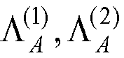
 die Systemmatrix A erzeugt wird, indem die Systemmatrixversionen (A(1), A(2)) kombiniert werden, die in Bezug auf die mehreren Empfangsvektorversionen erzeugt werden, aus welchen die Kovarianzmatrix R erzeugt wird (240);jede Empfangsvektorversion (r1, r2) auf einen Vektor (
 mehrere Produkte (228, 229) derart erzeugt werden, daß für jede der empfangenen Vektorversionen ein Produkt genommen wird aus:der Fouriertransformierten der erweiterten Empfangsvektorversion (
 der jeweiligen Diagonalmatrixversion (
 die mehreren Produkte summiert werden (225); undDaten der K Datensignale unter Verwendung einer inversen Fouriertransformation der summierten Produkte (220) und einer Cholesky-Zerlegung der aus der Kovarianzmatrix R abgeleiteten Diagonalmatrix ΛR geschätzt werden.
 - Verfahren nach Anspruch 1, wobei die Fouriertransformationen unter Verwendung einer schnellen Primfaktoralgorithmus-Fouriertransformation durchgeführt werden.
- Verfahren nach Anspruch 1, wobei jede Empfangsvektorversion einer anderen Empfangsantenne entspricht.
- Verfahren nach Anspruch 1, wobei das kombinierte Signal mit einem Vielfachen einer Chiprate der K Datensignale abgetastet wird und jede Empfangsvektorversion einem anderen Chipratenvielfachen entspricht.
- Verfahren nach Anspruch 1, wobei die K Datensignale über mehrere Antennen empfangen werden und mit einem Vielfachen einer Chiprate der K Datensignale abgetastet werden und jede Empfangsvektorversion einer anderen Kombination einer Antenne und eines Chipratenvielfachen entspricht.
- Verfahren nach Anspruch 1, das ferner das Zerlegen der Diagonalmatrizen in mehrere Teile aufweist.
- Verfahren nach Anspruch 1, wobei das Schätzen von Daten der K Datensignale das Durchführen einer LU-Zerlegung, Vorwärtssubstitution und Rückwärtssubstitution umfasst.
- Verfahren nach Anspruch 1, wobei das Schätzen von Daten der K Datensignale das Durchführen einer Cholesky-Zerlegung, Vorwärtssubstitution und Rückwärtssubstitution umfasst.
- Verfahren nach Anspruch 1, wobei die LU-Zerlegung oder Cholesky-Zerlegung für die Diagonale der Kovarianzmatrix durchgeführt wird.
- Kommunikationsstation, die aufgebaut ist, um Daten aus K Datensignalen zu detektieren, die über ein gemeinsam genutztes Spektrum in einem Codeteilungs-Vielfachzugriffformat übertragen werden, die eine Einrichtung hat, um ein über das gemeinsam genutzte Spektrum übertragenes kombiniertes Empfangssignal, das die K übertragenen Datensignale umfasst, abzutasten (43), um einen Empfangsvektor zu erzeugen, wobei die Einrichtung zum Abtasten (43 bis 431-2) aufgebaut ist, um mehrere Empfangsvektorversionen (r1 ... r2) zu erzeugen, eine Einrichtung zum Erzeugen einer Systemmatrix A, eine Einrichtung zum Erzeugen einer zugehörigen Kovarianzmatrix R, indem Codes und geschätzte Impulsantworten der K Datensignale verwendet werden (44, 48, 49), eine Einrichtung zum Erweitern und Annähern der Kovarianzmatrix R der Größe N*K mal N*K als eine blockzirkulante Matrix Rc (50) der Größe D*K mal D*K, indem sie mit Nullen aufgefüllt wird, so daß D > [N + (W - 1) / Q], wobei N eine Anzahl von Datensymbolen ist, W eine Impulsantwortlänge ist, Q ein Spreizfaktor ist und [·] eine Aufrundung auf eine ganzzahlige Funktion ist, eine Einrichtung zum Bestimmen einer Diagonalmatrix (ΛR) der erweiterten und genäherten Kovarianzmatrix Rc, indem unter Verwendung einer Blockspalte der erweiterten und genäherten Kovarianzmatrix Rc eine Block-DFT durchgeführt wird (52), und eine Einrichtung zum Erweitern des Empfangsvektors (51) und Durchführen einer Fouriertransformation davon (53), wobei die Kommunikationsstation dadurch gekennzeichnet ist, daß:die Einrichtung zum Erzeugen einer Systemmatrix A umfasst:eine Einrichtung zum Erzeugen einer Systemmatrixversion (A(1) , A(2) ) für jede Vektorversion unter Verwendung von Codes (c(k)) und geschätzten Impulsantworten (h (k)
(1) , h (k)(2) ) der K Datensignale (2041-m) ; undeine Einrichtung zum Kombinieren der Systemmatrixversionen (A(1), A(2), 240), um die Systemmatrix A zu erzeugen;eine Einrichtung zum Bestimmen einer jeweiligen Diagonalmatrixversion (
 eine Einrichtung zum Erweitern jeder Empfangsvektorversion (r1, r2, 2321-2) auf einen Vektor (
 und eine Einrichtung zum Durchführen einer Fouriertransformation jeder erweiterten Empfangsvektorversion (2001-2);eine Einrichtung zum Erzeugen mehrerer Produkte (228, 229) derart, daß für jede der empfangenen Vektorversionen ein Produkt genommen wird aus:der Fouriertransformierten der erweiterten Empfangsvektorversion (
 der jeweiligen Diagonalmatrixversion (
 eine Einrichtung zum Summieren der mehreren Produkte (225); undeine Einrichtung zum Schätzen von Daten der K Datensignale unter Verwendung einer inversen Fouriertransformation der summierten Produkte (220) und einer Cholesky-Zerlegung der aus der Kovarianzmatrix R abgeleiteten Diagonalmatrix ΛR.
 - Kommunikationsstation nach Anspruch 10, wobei die Einrichtung zum Durchführen einer Fouriertransformation von jeder erweiterten Empfangsvektorversion (2001-2) aufgebaut sind, um die Fouriertransformationen unter Verwendung einer schnellen Primfaktoralgorithmus-Foutiertransformation durchzuführen.
- Kommunikationsstation nach Anspruch 10, die ferner mehrere Antennen aufweist, die zu der Abtasteinrichtung gehören, so daß jede Empfangsvektorversion einer anderen Empfangsantenne entspricht.
- Kommunikationsstation nach Anspruch 10, wobei die Abtasteinrichtung derart aufgebaut ist, daß das kombinierte Signal mit einem Vielfachen einer Chiprate der K Datensignale abgetastet wird und jede Empfangsvektorversion einem anderen Chipratenvielfachen entspricht.
- Kommunikationsstation nach Anspruch 10, die ferner mehrere Antennen aufweist, die zu der Abtasteinrichtung gehören, so daß die K Datensignale über mehrere Antennen empfangen werden, und die Abtasteinrichtung derart aufgebaut ist, daß die K Datensignale mit einem Vielfachen einer Chiprate der K Datensignale abgetastet werden, und jede Empfangsvektorversion einer anderen Kombination einer Antenne und eines Chipratenvielfachen entspricht.
- Kommunikationsstation nach Anspruch 10, die ferner eine Einrichtung zum Zerlegen der Diagonalmatrixversionen in mehrere Teile aufweist.
- Kommunikationsstation nach Anspruch 10, wobei die Einrichtung zum Schätzen der Daten der K Datensignale aufgebaut ist, um eine LU-Zerlegung, Vorwärtssubstitution und Rückwärtssubstitution durchzuführen.
- Kommunikationsstation nach Anspruch 10, wobei die Einrichtung zum Schätzen der Daten der K Datensignale aufgebaut ist, um eine Cholesky-Zerlegung, Vorwärtssubstitution und Rückwärtssubstitution durchzuführen.
- Kommunikationsstation nach Anspruch 10, wobei die Einrichtung zum Schätzen der Daten der K Datensignale aufgebaut ist, um die LU-Zerlegung für die Diagonale der Kovarianzmatrix durchzuführen.
- Kommunikationsstation nach Anspruch 10, wobei die Einrichtung zum Schätzen der K Datensignale aufgebaut ist, um die Cholesky-Zerlegung für die Diagonale der Kovarianzmatrix durchzuführen.
- Kommunikationsstation nach einem der Ansprüche 10 - 19, die als eine Basisstation aufgebaut ist.
- Kommunikationsstation nach einem der Ansprüche 10 - 19, die als ein Benutzergerät aufgebaut ist.
Priority Applications (1)
| Application Number | Priority Date | Filing Date | Title |
|---|---|---|---|
| EP09161683A EP2093895A1 (de) | 2002-08-20 | 2003-08-15 | Schnelle Auskreuzungsdetektion |
Applications Claiming Priority (3)
| Application Number | Priority Date | Filing Date | Title |
|---|---|---|---|
| US40456102P | 2002-08-20 | 2002-08-20 | |
| US404561P | 2002-08-20 | ||
| PCT/US2003/025555 WO2004019159A2 (en) | 2002-08-20 | 2003-08-15 | Efficient joint detection |
Related Child Applications (1)
| Application Number | Title | Priority Date | Filing Date |
|---|---|---|---|
| EP09161683A Division EP2093895A1 (de) | 2002-08-20 | 2003-08-15 | Schnelle Auskreuzungsdetektion |
Publications (3)
| Publication Number | Publication Date |
|---|---|
| EP1552405A2 EP1552405A2 (de) | 2005-07-13 |
| EP1552405A4 EP1552405A4 (de) | 2006-03-22 |
| EP1552405B1 true EP1552405B1 (de) | 2009-06-03 |
Family
ID=31946728
Family Applications (2)
| Application Number | Title | Priority Date | Filing Date |
|---|---|---|---|
| EP09161683A Withdrawn EP2093895A1 (de) | 2002-08-20 | 2003-08-15 | Schnelle Auskreuzungsdetektion |
| EP03793067A Expired - Lifetime EP1552405B1 (de) | 2002-08-20 | 2003-08-15 | Effiziente gemeinsame detektion |
Family Applications Before (1)
| Application Number | Title | Priority Date | Filing Date |
|---|---|---|---|
| EP09161683A Withdrawn EP2093895A1 (de) | 2002-08-20 | 2003-08-15 | Schnelle Auskreuzungsdetektion |
Country Status (8)
| Country | Link |
|---|---|
| US (3) | US7289552B2 (de) |
| EP (2) | EP2093895A1 (de) |
| CN (1) | CN100592279C (de) |
| AT (1) | ATE433160T1 (de) |
| AU (1) | AU2003256426A1 (de) |
| DE (1) | DE60327874D1 (de) |
| TW (3) | TW200727604A (de) |
| WO (1) | WO2004019159A2 (de) |
Families Citing this family (22)
| Publication number | Priority date | Publication date | Assignee | Title |
|---|---|---|---|---|
| US6625203B2 (en) * | 2001-04-30 | 2003-09-23 | Interdigital Technology Corporation | Fast joint detection |
| AU2003256426A1 (en) * | 2002-08-20 | 2004-03-11 | Interdigital Technology Corporation | Efficient joint detection |
| WO2004064298A2 (en) * | 2003-01-10 | 2004-07-29 | Interdigital Technology Corporation | Generalized two-stage data estimation |
| CN100492949C (zh) * | 2003-01-21 | 2009-05-27 | 大唐移动通信设备有限公司 | 时隙码分多址系统多码集信道估计方法 |
| GB2404822B (en) * | 2003-08-07 | 2007-07-11 | Ipwireless Inc | Method and arrangement for noise variance and sir estimation |
| US7437135B2 (en) | 2003-10-30 | 2008-10-14 | Interdigital Technology Corporation | Joint channel equalizer interference canceller advanced receiver |
| US7400692B2 (en) | 2004-01-14 | 2008-07-15 | Interdigital Technology Corporation | Telescoping window based equalization |
| US7738595B2 (en) * | 2004-07-02 | 2010-06-15 | James Stuart Wight | Multiple input, multiple output communications systems |
| US7548592B2 (en) * | 2004-07-02 | 2009-06-16 | James Stuart Wight | Multiple input, multiple output communications systems |
| SG121024A1 (en) * | 2004-09-30 | 2006-04-26 | Agency Science Tech & Res | Fast method and receiver for cdma joint detection |
| US7844232B2 (en) * | 2005-05-25 | 2010-11-30 | Research In Motion Limited | Joint space-time optimum filters (JSTOF) with at least one antenna, at least one channel, and joint filter weight and CIR estimation |
| CN100488069C (zh) * | 2005-05-27 | 2009-05-13 | 展讯通信(上海)有限公司 | 一种td-scdma系统中联合小区检测方法 |
| KR100925763B1 (ko) * | 2005-07-06 | 2009-11-11 | 지티이 코포레이션 | 조인트 송신 기술에 기반한 업링크 동기 구축 방법 및 그 전송 매트릭스 |
| EP2007028B1 (de) * | 2006-03-31 | 2015-07-01 | NEC Corporation | Empfänger |
| FI20065276A0 (fi) * | 2006-04-28 | 2006-04-28 | Nokia Corp | Signaalin käsittelymenetelmä, vastaanotin ja tasoitusmenetelmä vastaanottimessa |
| CN101621354B (zh) * | 2008-07-06 | 2013-07-31 | 财团法人工业技术研究院 | 讯号侦测方法及使用该方法的接收装置 |
| US20100011039A1 (en) * | 2008-07-11 | 2010-01-14 | James Vannucci | Device and method for solving a system of equations |
| US20120281747A1 (en) * | 2011-05-02 | 2012-11-08 | Qualcomm Incorporated | Equalizer tap determination |
| US10735023B2 (en) | 2017-02-24 | 2020-08-04 | Texas Instruments Incorporated | Matrix compression accelerator system and method |
| US10810281B2 (en) | 2017-02-24 | 2020-10-20 | Texas Instruments Incorporated | Outer product multipler system and method |
| US10817587B2 (en) | 2017-02-28 | 2020-10-27 | Texas Instruments Incorporated | Reconfigurable matrix multiplier system and method |
| US11086967B2 (en) | 2017-03-01 | 2021-08-10 | Texas Instruments Incorporated | Implementing fundamental computational primitives using a matrix multiplication accelerator (MMA) |
Family Cites Families (17)
| Publication number | Priority date | Publication date | Assignee | Title |
|---|---|---|---|---|
| US5588032A (en) | 1992-10-14 | 1996-12-24 | Johnson; Steven A. | Apparatus and method for imaging with wavefields using inverse scattering techniques |
| US6208295B1 (en) | 1995-06-02 | 2001-03-27 | Trw Inc. | Method for processing radio signals that are subject to unwanted change during propagation |
| JPH09212489A (ja) | 1996-01-31 | 1997-08-15 | Fujitsu Ltd | 対称行列の固有値問題を解く並列処理装置および方法 |
| WO1998009385A2 (en) | 1996-08-29 | 1998-03-05 | Cisco Technology, Inc. | Spatio-temporal processing for communication |
| JP3938238B2 (ja) | 1997-02-04 | 2007-06-27 | 沖電気工業株式会社 | 高速フーリエ変換処理装置 |
| GB9802445D0 (en) | 1998-02-05 | 1998-04-01 | Marconi Gec Ltd | Optical links |
| US6339612B1 (en) | 1998-02-09 | 2002-01-15 | Motorola, Inc. | Method and apparatus for joint detection of data in a direct sequence spread spectrum communications system |
| FR2793363B1 (fr) | 1999-05-04 | 2001-07-06 | France Telecom | Procede de detection conjointe d'un ensemble de codes cdma |
| US6370129B1 (en) | 1999-06-28 | 2002-04-09 | Lucent Technologies, Inc. | High-speed data services using multiple transmit antennas |
| FR2800948B1 (fr) | 1999-11-08 | 2002-03-01 | Mitsubishi Electric Inf Tech | Procede de detection conjointe |
| US6252540B1 (en) | 1999-12-21 | 2001-06-26 | The United States Of America As Represented By The Secretary Of The Air Force | Apparatus and method for two stage hybrid space-time adaptive processing in radar and communication systems |
| JP4018978B2 (ja) | 2000-08-03 | 2007-12-05 | 富士通株式会社 | 半導体装置および半導体装置上に配置されるヒートシンクを載置し、基板に固定する取付け具およびその取付け方法 |
| EP1364506A2 (de) * | 2001-02-22 | 2003-11-26 | Koninklijke Philips Electronics N.V. | Mehrträger-übertragungssystem mit kanalantwortabschätzung mit verringerter komplexität |
| US6625203B2 (en) * | 2001-04-30 | 2003-09-23 | Interdigital Technology Corporation | Fast joint detection |
| US6952460B1 (en) * | 2001-09-26 | 2005-10-04 | L-3 Communications Corporation | Efficient space-time adaptive processing (STAP) filter for global positioning system (GPS) receivers |
| US6424596B1 (en) | 2001-10-01 | 2002-07-23 | The United States Of America As Represented By The Secretary Of The Navy | Method and apparatus for reducing noise from near ocean surface sources |
| AU2003256426A1 (en) | 2002-08-20 | 2004-03-11 | Interdigital Technology Corporation | Efficient joint detection |
-
2003
- 2003-08-15 AU AU2003256426A patent/AU2003256426A1/en not_active Abandoned
- 2003-08-15 EP EP09161683A patent/EP2093895A1/de not_active Withdrawn
- 2003-08-15 WO PCT/US2003/025555 patent/WO2004019159A2/en not_active Ceased
- 2003-08-15 AT AT03793067T patent/ATE433160T1/de not_active IP Right Cessation
- 2003-08-15 DE DE60327874T patent/DE60327874D1/de not_active Expired - Fee Related
- 2003-08-15 EP EP03793067A patent/EP1552405B1/de not_active Expired - Lifetime
- 2003-08-15 CN CN03819728A patent/CN100592279C/zh not_active Expired - Fee Related
- 2003-08-18 TW TW095130729A patent/TW200727604A/zh unknown
- 2003-08-18 TW TW093110152A patent/TWI320535B/zh not_active IP Right Cessation
- 2003-08-18 TW TW092122679A patent/TWI260173B/zh not_active IP Right Cessation
- 2003-08-20 US US10/644,361 patent/US7289552B2/en not_active Expired - Fee Related
-
2007
- 2007-10-29 US US11/926,534 patent/US7483475B2/en not_active Expired - Fee Related
-
2009
- 2009-01-23 US US12/358,739 patent/US7643584B2/en not_active Expired - Fee Related
Also Published As
| Publication number | Publication date |
|---|---|
| TWI260173B (en) | 2006-08-11 |
| EP1552405A2 (de) | 2005-07-13 |
| US20090129447A1 (en) | 2009-05-21 |
| EP2093895A1 (de) | 2009-08-26 |
| US20040136316A1 (en) | 2004-07-15 |
| US7483475B2 (en) | 2009-01-27 |
| TW200727604A (en) | 2007-07-16 |
| AU2003256426A1 (en) | 2004-03-11 |
| TW200508897A (en) | 2005-03-01 |
| DE60327874D1 (de) | 2009-07-16 |
| CN100592279C (zh) | 2010-02-24 |
| TW200407039A (en) | 2004-05-01 |
| ATE433160T1 (de) | 2009-06-15 |
| US7289552B2 (en) | 2007-10-30 |
| EP1552405A4 (de) | 2006-03-22 |
| TWI320535B (en) | 2010-02-11 |
| AU2003256426A8 (en) | 2004-03-11 |
| CN1675630A (zh) | 2005-09-28 |
| WO2004019159A2 (en) | 2004-03-04 |
| US7643584B2 (en) | 2010-01-05 |
| WO2004019159A3 (en) | 2004-07-08 |
| US20080062860A1 (en) | 2008-03-13 |
Similar Documents
| Publication | Publication Date | Title |
|---|---|---|
| US7643584B2 (en) | Efficient joint detection | |
| US7768986B2 (en) | Method and apparatus for receiving plurality of data signals | |
| EP1391048B1 (de) | Schnelle auskreuzungsdetektion | |
| US7609750B2 (en) | Segment-wise channel equalization based data estimation |
Legal Events
| Date | Code | Title | Description |
|---|---|---|---|
| PUAI | Public reference made under article 153(3) epc to a published international application that has entered the european phase |
Free format text: ORIGINAL CODE: 0009012 |
|
| 17P | Request for examination filed |
Effective date: 20050210 |
|
| AK | Designated contracting states |
Kind code of ref document: A2 Designated state(s): AT BE BG CH CY CZ DE DK EE ES FI FR GB GR HU IE IT LI LU MC NL PT RO SE SI SK TR |
|
| AX | Request for extension of the european patent |
Extension state: AL LT LV MK |
|
| DAX | Request for extension of the european patent (deleted) | ||
| A4 | Supplementary search report drawn up and despatched |
Effective date: 20060208 |
|
| 17Q | First examination report despatched |
Effective date: 20060627 |
|
| RIN1 | Information on inventor provided before grant (corrected) |
Inventor name: KWAK, JAEYOUNG Inventor name: ZEIRA, ARIELA Inventor name: PAN, JUNG-LIN Inventor name: HAIM, JOHN, W. |
|
| GRAP | Despatch of communication of intention to grant a patent |
Free format text: ORIGINAL CODE: EPIDOSNIGR1 |
|
| GRAS | Grant fee paid |
Free format text: ORIGINAL CODE: EPIDOSNIGR3 |
|
| GRAA | (expected) grant |
Free format text: ORIGINAL CODE: 0009210 |
|
| RAP1 | Party data changed (applicant data changed or rights of an application transferred) |
Owner name: INTERDIGITAL TECHNOLOGY CORPORATION |
|
| AK | Designated contracting states |
Kind code of ref document: B1 Designated state(s): AT BE BG CH CY CZ DE DK EE ES FI FR GB GR HU IE IT LI LU MC NL PT RO SE SI SK TR |
|
| REG | Reference to a national code |
Ref country code: GB Ref legal event code: FG4D |
|
| REG | Reference to a national code |
Ref country code: CH Ref legal event code: EP |
|
| REG | Reference to a national code |
Ref country code: IE Ref legal event code: FG4D |
|
| REF | Corresponds to: |
Ref document number: 60327874 Country of ref document: DE Date of ref document: 20090716 Kind code of ref document: P |
|
| PG25 | Lapsed in a contracting state [announced via postgrant information from national office to epo] |
Ref country code: FI Free format text: LAPSE BECAUSE OF FAILURE TO SUBMIT A TRANSLATION OF THE DESCRIPTION OR TO PAY THE FEE WITHIN THE PRESCRIBED TIME-LIMIT Effective date: 20090603 Ref country code: AT Free format text: LAPSE BECAUSE OF FAILURE TO SUBMIT A TRANSLATION OF THE DESCRIPTION OR TO PAY THE FEE WITHIN THE PRESCRIBED TIME-LIMIT Effective date: 20090603 |
|
| PG25 | Lapsed in a contracting state [announced via postgrant information from national office to epo] |
Ref country code: SE Free format text: LAPSE BECAUSE OF FAILURE TO SUBMIT A TRANSLATION OF THE DESCRIPTION OR TO PAY THE FEE WITHIN THE PRESCRIBED TIME-LIMIT Effective date: 20090903 Ref country code: SI Free format text: LAPSE BECAUSE OF FAILURE TO SUBMIT A TRANSLATION OF THE DESCRIPTION OR TO PAY THE FEE WITHIN THE PRESCRIBED TIME-LIMIT Effective date: 20090603 |
|
| PG25 | Lapsed in a contracting state [announced via postgrant information from national office to epo] |
Ref country code: CZ Free format text: LAPSE BECAUSE OF FAILURE TO SUBMIT A TRANSLATION OF THE DESCRIPTION OR TO PAY THE FEE WITHIN THE PRESCRIBED TIME-LIMIT Effective date: 20090603 Ref country code: EE Free format text: LAPSE BECAUSE OF FAILURE TO SUBMIT A TRANSLATION OF THE DESCRIPTION OR TO PAY THE FEE WITHIN THE PRESCRIBED TIME-LIMIT Effective date: 20090603 Ref country code: ES Free format text: LAPSE BECAUSE OF FAILURE TO SUBMIT A TRANSLATION OF THE DESCRIPTION OR TO PAY THE FEE WITHIN THE PRESCRIBED TIME-LIMIT Effective date: 20090914 Ref country code: RO Free format text: LAPSE BECAUSE OF FAILURE TO SUBMIT A TRANSLATION OF THE DESCRIPTION OR TO PAY THE FEE WITHIN THE PRESCRIBED TIME-LIMIT Effective date: 20090603 |
|
| PG25 | Lapsed in a contracting state [announced via postgrant information from national office to epo] |
Ref country code: SK Free format text: LAPSE BECAUSE OF FAILURE TO SUBMIT A TRANSLATION OF THE DESCRIPTION OR TO PAY THE FEE WITHIN THE PRESCRIBED TIME-LIMIT Effective date: 20090603 Ref country code: BE Free format text: LAPSE BECAUSE OF FAILURE TO SUBMIT A TRANSLATION OF THE DESCRIPTION OR TO PAY THE FEE WITHIN THE PRESCRIBED TIME-LIMIT Effective date: 20090603 |
|
| PG25 | Lapsed in a contracting state [announced via postgrant information from national office to epo] |
Ref country code: PT Free format text: LAPSE BECAUSE OF FAILURE TO SUBMIT A TRANSLATION OF THE DESCRIPTION OR TO PAY THE FEE WITHIN THE PRESCRIBED TIME-LIMIT Effective date: 20091003 Ref country code: BG Free format text: LAPSE BECAUSE OF FAILURE TO SUBMIT A TRANSLATION OF THE DESCRIPTION OR TO PAY THE FEE WITHIN THE PRESCRIBED TIME-LIMIT Effective date: 20090903 Ref country code: MC Free format text: LAPSE BECAUSE OF NON-PAYMENT OF DUE FEES Effective date: 20090831 |
|
| REG | Reference to a national code |
Ref country code: NL Ref legal event code: V1 Effective date: 20100301 Ref country code: CH Ref legal event code: PL |
|
| PLBE | No opposition filed within time limit |
Free format text: ORIGINAL CODE: 0009261 |
|
| STAA | Information on the status of an ep patent application or granted ep patent |
Free format text: STATUS: NO OPPOSITION FILED WITHIN TIME LIMIT |
|
| PG25 | Lapsed in a contracting state [announced via postgrant information from national office to epo] |
Ref country code: CH Free format text: LAPSE BECAUSE OF NON-PAYMENT OF DUE FEES Effective date: 20090831 Ref country code: LI Free format text: LAPSE BECAUSE OF NON-PAYMENT OF DUE FEES Effective date: 20090831 Ref country code: DK Free format text: LAPSE BECAUSE OF FAILURE TO SUBMIT A TRANSLATION OF THE DESCRIPTION OR TO PAY THE FEE WITHIN THE PRESCRIBED TIME-LIMIT Effective date: 20090603 |
|
| 26N | No opposition filed |
Effective date: 20100304 |
|
| REG | Reference to a national code |
Ref country code: FR Ref legal event code: ST Effective date: 20100430 |
|
| GBPC | Gb: european patent ceased through non-payment of renewal fee |
Effective date: 20090903 |
|
| PG25 | Lapsed in a contracting state [announced via postgrant information from national office to epo] |
Ref country code: FR Free format text: LAPSE BECAUSE OF NON-PAYMENT OF DUE FEES Effective date: 20090831 Ref country code: NL Free format text: LAPSE BECAUSE OF NON-PAYMENT OF DUE FEES Effective date: 20100301 Ref country code: IE Free format text: LAPSE BECAUSE OF NON-PAYMENT OF DUE FEES Effective date: 20090815 Ref country code: DE Free format text: LAPSE BECAUSE OF NON-PAYMENT OF DUE FEES Effective date: 20100302 |
|
| PG25 | Lapsed in a contracting state [announced via postgrant information from national office to epo] |
Ref country code: GR Free format text: LAPSE BECAUSE OF FAILURE TO SUBMIT A TRANSLATION OF THE DESCRIPTION OR TO PAY THE FEE WITHIN THE PRESCRIBED TIME-LIMIT Effective date: 20090904 |
|
| PG25 | Lapsed in a contracting state [announced via postgrant information from national office to epo] |
Ref country code: GB Free format text: LAPSE BECAUSE OF NON-PAYMENT OF DUE FEES Effective date: 20090903 |
|
| PG25 | Lapsed in a contracting state [announced via postgrant information from national office to epo] |
Ref country code: IT Free format text: LAPSE BECAUSE OF FAILURE TO SUBMIT A TRANSLATION OF THE DESCRIPTION OR TO PAY THE FEE WITHIN THE PRESCRIBED TIME-LIMIT Effective date: 20090603 |
|
| PG25 | Lapsed in a contracting state [announced via postgrant information from national office to epo] |
Ref country code: LU Free format text: LAPSE BECAUSE OF NON-PAYMENT OF DUE FEES Effective date: 20090815 |
|
| PG25 | Lapsed in a contracting state [announced via postgrant information from national office to epo] |
Ref country code: HU Free format text: LAPSE BECAUSE OF FAILURE TO SUBMIT A TRANSLATION OF THE DESCRIPTION OR TO PAY THE FEE WITHIN THE PRESCRIBED TIME-LIMIT Effective date: 20091204 |
|
| PG25 | Lapsed in a contracting state [announced via postgrant information from national office to epo] |
Ref country code: TR Free format text: LAPSE BECAUSE OF FAILURE TO SUBMIT A TRANSLATION OF THE DESCRIPTION OR TO PAY THE FEE WITHIN THE PRESCRIBED TIME-LIMIT Effective date: 20090603 |
|
| PG25 | Lapsed in a contracting state [announced via postgrant information from national office to epo] |
Ref country code: CY Free format text: LAPSE BECAUSE OF FAILURE TO SUBMIT A TRANSLATION OF THE DESCRIPTION OR TO PAY THE FEE WITHIN THE PRESCRIBED TIME-LIMIT Effective date: 20090603 |