EP1552474B1 - Procede d'interpolation et d'affinage d'images - Google Patents
Procede d'interpolation et d'affinage d'images Download PDFInfo
- Publication number
- EP1552474B1 EP1552474B1 EP03750765A EP03750765A EP1552474B1 EP 1552474 B1 EP1552474 B1 EP 1552474B1 EP 03750765 A EP03750765 A EP 03750765A EP 03750765 A EP03750765 A EP 03750765A EP 1552474 B1 EP1552474 B1 EP 1552474B1
- Authority
- EP
- European Patent Office
- Prior art keywords
- colour component
- sharpening
- value
- colour
- change
- Prior art date
- Legal status (The legal status is an assumption and is not a legal conclusion. Google has not performed a legal analysis and makes no representation as to the accuracy of the status listed.)
- Expired - Lifetime
Links
Images


Classifications
-
- G—PHYSICS
- G06—COMPUTING OR CALCULATING; COUNTING
- G06T—IMAGE DATA PROCESSING OR GENERATION, IN GENERAL
- G06T5/00—Image enhancement or restoration
- G06T5/73—Deblurring; Sharpening
-
- G—PHYSICS
- G06—COMPUTING OR CALCULATING; COUNTING
- G06T—IMAGE DATA PROCESSING OR GENERATION, IN GENERAL
- G06T11/00—Two-dimensional [2D] image generation
- G06T11/10—Texturing; Colouring; Generation of textures or colours
-
- G—PHYSICS
- G06—COMPUTING OR CALCULATING; COUNTING
- G06T—IMAGE DATA PROCESSING OR GENERATION, IN GENERAL
- G06T5/00—Image enhancement or restoration
- G06T5/20—Image enhancement or restoration using local operators
-
- H—ELECTRICITY
- H04—ELECTRIC COMMUNICATION TECHNIQUE
- H04N—PICTORIAL COMMUNICATION, e.g. TELEVISION
- H04N1/00—Scanning, transmission or reproduction of documents or the like, e.g. facsimile transmission; Details thereof
- H04N1/40—Picture signal circuits
-
- H—ELECTRICITY
- H04—ELECTRIC COMMUNICATION TECHNIQUE
- H04N—PICTORIAL COMMUNICATION, e.g. TELEVISION
- H04N1/00—Scanning, transmission or reproduction of documents or the like, e.g. facsimile transmission; Details thereof
- H04N1/46—Colour picture communication systems
- H04N1/56—Processing of colour picture signals
- H04N1/58—Edge or detail enhancement; Noise or error suppression, e.g. colour misregistration correction
-
- H—ELECTRICITY
- H04—ELECTRIC COMMUNICATION TECHNIQUE
- H04N—PICTORIAL COMMUNICATION, e.g. TELEVISION
- H04N1/00—Scanning, transmission or reproduction of documents or the like, e.g. facsimile transmission; Details thereof
- H04N1/46—Colour picture communication systems
- H04N1/56—Processing of colour picture signals
- H04N1/60—Colour correction or control
-
- H—ELECTRICITY
- H04—ELECTRIC COMMUNICATION TECHNIQUE
- H04N—PICTORIAL COMMUNICATION, e.g. TELEVISION
- H04N5/00—Details of television systems
- H04N5/76—Television signal recording
-
- H—ELECTRICITY
- H04—ELECTRIC COMMUNICATION TECHNIQUE
- H04N—PICTORIAL COMMUNICATION, e.g. TELEVISION
- H04N9/00—Details of colour television systems
- H04N9/64—Circuits for processing colour signals
- H04N9/646—Circuits for processing colour signals for image enhancement, e.g. vertical detail restoration, cross-colour elimination, contour correction, chrominance trapping filters
-
- G—PHYSICS
- G06—COMPUTING OR CALCULATING; COUNTING
- G06T—IMAGE DATA PROCESSING OR GENERATION, IN GENERAL
- G06T2207/00—Indexing scheme for image analysis or image enhancement
- G06T2207/10—Image acquisition modality
- G06T2207/10024—Color image
-
- G—PHYSICS
- G06—COMPUTING OR CALCULATING; COUNTING
- G06T—IMAGE DATA PROCESSING OR GENERATION, IN GENERAL
- G06T2207/00—Indexing scheme for image analysis or image enhancement
- G06T2207/20—Special algorithmic details
- G06T2207/20004—Adaptive image processing
- G06T2207/20012—Locally adaptive
-
- G—PHYSICS
- G06—COMPUTING OR CALCULATING; COUNTING
- G06T—IMAGE DATA PROCESSING OR GENERATION, IN GENERAL
- G06T2207/00—Indexing scheme for image analysis or image enhancement
- G06T2207/20—Special algorithmic details
- G06T2207/20172—Image enhancement details
- G06T2207/20192—Edge enhancement; Edge preservation
Definitions
- the present invention relates to a method for sharpening images as presented in the preamble of the appended claim 1.
- the present invention also relates to a digital filter for processing digital signals in an image as presented in the preamble of the appended claim 17.
- the present invention also relates to a system as presented in the preamble of the appended claim 18.
- the present invention relates to a device as presented in the preamble of the appended claim 21, a storage means as presented in the preamble of the appended claim 25, and a computer software product as presented in the preamble of the appended claim 26.
- Images taken by means for storing digital images such as digital cameras, camera phones, or other cameras equipped with a single complementary metal-oxide semiconductor (CMOS) or with a single charge coupled device (CCD), do not comprise all colour component values for each pixel.
- CMOS complementary metal-oxide semiconductor
- CCD charge coupled device
- the aim is to use only one (in some situations more than one can be used as well) image sensor in smaller devices (camera devices), wherein a so-called colour filter array (CFA), such as the Bayer matrix, is needed for forming the image.
- CFA colour filter array
- the Bayer matrix is a common colour array, in which only one colour is sampled in each pixel and which causes that the other colours of the colour system are lacking from each pixel.
- the RGB colour system Red, Green Blue
- half of the pixels in the Bayer matrix form the green colour component and the other half of the pixels form the blue and the red colour component, and the values of the other colour tones are lacking from each pixel. This creates a need to interpolate the missing colour samples so that the image can be stored in its complete format.
- the known RGB colour system when referring to colours, the known RGB colour system will be used, which defines the colour by means of the relationship between red (R), green (G) and blue (B).
- the known RGB colour system when referring to colours, the known RGB colour system will be used, which defines the colour by means of the relationship between red (R), green (G) and blue (B).
- the colour component can also be described by the CMY colour system (Cyan-Magenta-Yellow), in which the colour is formed by values of cyan (C), magenta (M) and yellow (Y).
- the colour system can also be any other corresponding system.
- the conversion of an image in the Bayer matrix format to an RGB image request the interpolation of the missing colour values in each pixel.
- the interpolation system can be exemplified with an interpolation system utilizing the nearest neighbour pixels (the nearest neighbour method), in which for example the interpolation of the missing blue and red colours is made according to the nearest neighbour pixel of the same colour, as well as with bilinear interpolation, which has been improved so that the interpolation of green is controlled by means of the other colour components.
- the nearest neighbour method the nearest neighbour pixels
- bilinear interpolation which has been improved so that the interpolation of green is controlled by means of the other colour components.
- the average values are computed for two neighbours of the same colour.
- point (c) is one where the blue colour is interpolated for a red pixel R.
- the green component G can be interpolated by using the closest neighbour pairs. Below, two cases are presented for interpolating the green component G. a) R1 b) B1 G1 G1 R4 G4 R G2 R2 B4 G4 B G2 B2 G3 G3 R3 B3
- the value of the green component G is interpolated for a red pixel R.
- the effect of the red component R is taken into account in the interpolation. If the difference between R1 and R3 is smaller than the difference between R2 and R4, it is noticed that the red R is stronger in the vertical direction, wherein the average value of the vertical neighbours G1 and G3 is used for computing the desired value in the interpolation. On the other hand, if the horizontal effect is greater, the adjacent neighbours are used respectively. If the ratio of red is the same throughout, all the four neighbours are used. In connection with the blue colour component B, a similar computation is made under point (b).
- Publication US 6,549,233 B1 discloses one method for colour interpolation by means of the Bayer matrix.
- the method of the publication includes calculating colour intensity gradients for the image, of which the highest and lowest gradient value is determined.
- the gradients are calculated between the first colour locating in the centre pixel of the matrix and the similar colours spaced from that.
- Calculated gradients are compared to threshold value, and if a gradient exceeds said threshold value (which is formed of the average of the intensities of the colour) in that colour, the intensity value of the centre pixel is used for the pixel spaced from it.
- US patent 5,247,352 discloses a method for sharpening a colour image.
- the sharpening is based on a three-dimensional colour space, for example the Munsell colour chart.
- the publication presents several switch states for defining the sum of colour difference signals and at least two sharpening signals.
- the switch states are set by means of a colour coordinate system.
- the system determines the pixel locations on the basis of the colour values of the pixels.
- the positions of the switches are based on position data.
- the device according to the publication can combine the desired sharpening signals with the colour difference signals. In this way, the image can be sharpened.
- the filtering of the second and the third colour components is adjusted on the basis of a value obtained from the colour space. After the interpolation, all the colour components must be sharpened, which causes triple work for the image processing, which, in turn, requires that the processing system has a high processing capacity.
- International publication WO 02/075654 discloses a solution for efficiently demosaicing input mosaiced images to reduce colour aliasing, non-coloured zippering artefacts along feature edges.
- the system utilizes an asymmetric interpolation scheme to equalize colour discontinuities in the resulting demosaiced images using discontinuities of the other remaining colour component.
- Interpolation of the first colour values includes adaptively interpolating the first colour value using a first or a second interpolation method.
- Interpolating the second colour values includes computing colour discontinuity equalization values using interpolated first colour values and averaged colour values.
- US patent 5,506,619 discloses an adaptive interpolation.
- a missing colour value is generated by the interpolation of an additional colour value.
- Laplacian second-order values in at least two image directions are obtained from nearby photosites of the same column and row.
- a preferred orientation for the interpolation of the missing value is selected, and the missing colour value is interpolated form nearby multiple colour values selected to agree with the preferred orientation.
- US patent 5,172,227 further discloses an image compression with colour interpolation for a single sensor image system.
- the colour interpolation consists of three steps: the missing green pixels are first filled in by vertical interpolation, then missing colour differences pixels are horizontally interpolated and then vertically interpolated.
- European patent application EP 1043688 A2 discloses an image recognition method an apparatus utilizing edge detection based on magnitudes of colour vectors expressing colour attributes of respective pixels of colour image.
- US patent 5,382,976 discloses an adaptive interpolating. Interpolating is performed by apparatus operating upon a digitized image signal obtained from an image sensor having color photosites that generate a plurality of color values, but only one color per photosite.
- a digital processor obtains gradient values from the differences between luminance values in vertical and horizontal image directions. The gradient values are compared to a threshold value in order to select one of the directions as the preferred orientation for the interpolation of additional luminance values.
- European patent application publication EP 0457427 A2 discloses an apparatus for sharpening a colour image having a multiplicity of colour separation signals defining plurality of color pixels comprising apparatus for generating at least two sharpening signals from the colour separation signals with any collection of the at least two sharpening signals wherein the collection changes throughout the image.
- the present invention improves the prior art by filtering the other colour components by utilizing the filtering result of a single colour component.
- the filtering in different components may cause different effects, wherein distortions may occur in the colours of the image.
- two kinds of undesired phenomena may occur, such as an increase in the noise and, particularly close to edges, excessive sharpening of the edge.
- This causes ringing, which is manifested, for example, as a black line in connection with a white line.
- one colour component is first interpolated and this interpolated colour component is sharpened. After this, the effect of the sharpening on the interpolated image is examined by deducing from each pixel of the sharpened image the corresponding pixel of the unsharpened image. If the effect of the sharpening on the first component was significantly high in a given pixel, the sharpening is performed for the second or third colour component, if there is one at the point in question.
- the possible pixel of the second or third colour component is kept unchanged.
- the original pixels of the second and third colour components are, for the necessary parts, already sharpened before the interpolation of these colour components.
- the filtering it is possible to use any filtering mask of prior art.
- the most advantageous final result is obtained by using such an adaptive sharpening filter which only processes those pixels which are true edge pixels, wherein the edge strength can be used in the control of the sharpening.
- the method for sharpening images according to the present invention is primarily characterized in what will be presented in the characterizing part of claim 1.
- the method for processing digital signals in an image is primarily characterized in what will be presented in characterizing part of claim 20.
- the digital filter for processing digital signals in an image is primarily characterized in what will be presented in characterizing part of claim 31.
- the system according to the invention is primarily characterized in what will be presented in the characterizing part of the independent claim 32.
- the device according to the invention is primarily characterized in what will be presented in the characterizing part of the independent claim 37.
- the storage means according to the invention is primarily characterized in what will be presented in the characterizing part of the independent claim 43.
- the computer software product according to the invention is primarily characterized in what will be presented in the characterizing part of the independent claim 45.
- the effect required by the computation can be reduced without affecting the quality of the image.
- the method according to the invention it is even possible to achieve a better image quality than in the conventional method, in which the whole sharpening of the image is made first after the interpolation.
- the sharpening method used in the invention is self-adaptive, wherein it is not used for sharpening uniform image areas, which will, in turn, reduce the quantity of noise in the image. Furthermore, by the method of the invention, the sharpening efficiencies are limited close to clear edges, to prevent ringing caused by over-sharpening. This makes the image more pleasant to look at.
- the size of the sharpening filter window (3 ⁇ 3) used in the invention has an advantageous effect on the memory loading, because most of the matrix rows do not need to be stored in the device as in the methods of prior art. Moreover, the size of the filter window reduces the heavy computing required in the processing, because the method is primarily based on making choices.
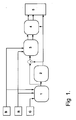
- Figure 1 shows the operating sequence of the method according to the invention for the interpolation and sharpening of a Bayer matrix image.
- Block 1 shows the interpolation of the image with respect to a first colour component G with full resolution in a known way.
- the first colour component G is preferably green because of the number of green pixels in relation to the number of blue and red pixels in the Bayer matrix (G:B:R 2:1:1). If the pixel numbers were different from those described, the first colour should be selected to be the colour component which the greatest number of pixels or the component whose change has the greatest effect on the luminance.
- the image is sharpened accordingly with respect to the first colour component G, as will be shown in block 2.
- the image is subjected to the sharpening of the second R and the third B colour components.
- the effect of the sharpening for the first colour component G is compared with the interpolated colour component G. If this effect (abs[Sharpened — Unsharpened]) is significant, the 2nd and 3rd colour components of the corresponding point are sharpened by using the change caused by the sharpening of the first colour component as such or in proportion to the changes in the neighbour pixel values. If the effect is low, no sharpening is made.
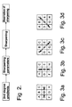
- Figure 2 shows the basic principle of the sharpening algorithm.
- the second degree gradients (Laplacian) are computed for the first colour component G, to be able to monitor the change on the colour component and the intensity of the change, whereby the true edge pixels can be detected.
- the computation can be advantageously implemented by computing the gradients in four different directions in a sample of 3 x3 pixels ( Fig. 3 ).
- the two outermost pixel values (D, E; B, G; A, H; C, F) are first summed up in a given direction, after which the sum is deducted from the original pixel value O which has been multiplied by two.
- the changes are normally more significant in the horizontal and vertical directions; therefore, the diagonal gradients are attenuated by multiplying them with a constant smaller than the figure one. Furthermore, it should be taken into account that in the diagonal directions, the distance between the adjacent pixels is greater than in the horizontal and vertical directions. The ratio between the distances is exactly 1 / 2 ⁇ 0.71.
- the coefficient 0.75 which is more advantageous than 0.71 in calculations, is used in the computation of GradNWSE and GradNESW.
- This value may also be another value, preferably smaller than the figure one, wherein the choice of either the horizontal or the vertical direction is preferred.
- the computed gradients represent the original change values, from where, the minimum and maximum values are searched. These minimum and maximum values are used to obtain the change values to be used in the sharpening.
- the first change value T1 is that absolute value which is smaller of the minimum and maximum absolute values.
- the other change value T2 is that absolute value which is larger of the minimum and maximum absolute values.
- the first change value T1 is that (absolute) value which is smaller of the absolute values of the (searched) minimum and maximum values
- the other change value T2 is that (absolute) value which is larger of the absolute values of the (searched) minimum and maximum values.
- the sharpening function of the first colour component is based on the ratio between these change values.
- Change values T2 and T1 indicate the greatest and the smallest changes, respectively. The ratio between these figures indicates how important a change has taken place. Furthermore, information is stored about sign of the gradient of the other change value (T2).
- the sharpening of the colour component is controlled on the basis of the changes so that if change value (T2) is not sufficiently great (preferably T2 ⁇ 2 when an 8-bit presentation form is used for the colour component), wherein the image area does not contain clear edges, and no sharpening is needed.
- change value (T2) is not sufficiently great (preferably T2 ⁇ 2 when an 8-bit presentation form is used for the colour component), wherein the image area does not contain clear edges, and no sharpening is needed.
- ratio T1 / T2 ).
- it is also possible to add a constant value ( const1, const2 ) to each change value T1, T2, wherein the following equation is formed: ratio T ⁇ 1 ⁇ + const ⁇ 1 ⁇ T ⁇ 2 ⁇ + const ⁇ 2 .
- the constants used in this equation can be unequal or equal to each other. Because of the image processing method or another factor relating to the properties of the image, it may be necessary to use unequal constants, but typically these constants are equal. It is also possible that the values are only constant on a given area in the image, in other words that different constant values are used in different areas of the image.
- the constant values (const1, const2) are small, preferably for example 3 or another value between 1 and 10.
- the computed ratio is compared with two predetermined limit values, Slim 1, Slim2.
- the few values of the ratio occur between the limit values, the faster the pixel value can be computed. With respect to the speed, it is advantageous that Slim2 is as small as possible.
- Sharpening will not be needed, if the change ratio is greater than or equal to the second limit value (Slim2) (ratio ⁇ Slim2). Thus, there may be noise in the image location, wherein the change values T1, T2 have the same sign and are almost equal. Another alternative is that the change values T1, T2 have opposite signs but an almost equal absolute value, wherein the direction of the sharpening cannot be predicted. In both cases, it is worthwhile not to perform sharpening.
- the change ratio is smaller than or equal to the first limit value (Slim1) (ration Slim1), it can be presumed that said pixels are true edge pixels, wherein maximum sharpening is used.
- the sharpening function is adjusted with a weight coefficient (weight).
- the limit values must be very close to these values to avoid excessive reduction of the effect of sharpening or to avoid sharpening of wrong pixels.
- the value of the sharpening function ( sharp ) is different from the original average pixel value (O)
- a final examination is made. If the proposed change in the sharpening function ( abs(sharp - O) ) is greater than the allowed predetermined sharpening limiter (over), the output value can be limited; in other words, over-sharpening is prevented.
- the value of the sharpening limiter (over) is preferably 40 (in an 8-bit system), but it can also be another value according to the preferences of the viewer.
- the output (sharp) cannot be smaller than the one with the smallest pixel value in the selected sharpening direction (Min(x, O, y), in which x and y are the outermost pixels in the environment of the central pixel O in the filtering window), from which the value of the sharpening limiter (over) has been deducted.
- the output cannot be greater than the greatest pixel in the selected sharpening direction (Max(x, O, y), x and y as above), to which the value of the sharpening limiter (over) has been added.
- the table hereinbelow shows the control value and the final sharpening output (final) after the selected sharpening direction has been examined.
- the final sharpening output is either the control value (CW) or the value of the sharpening function (sharp).
- Max(sharp, CW) means that the final output is either the control value (CW) or the value of the sharpening function (sharp), depending on which one is greater.
- Min(sharp, CW) means that the final output is either the control value (CW) or the value of the sharpening function (sharp), depending on which one is smaller.
- the above-presented limit values Slim1 and Slim2 do not change when the value range of the colour system is changed, for example, from 8 bits to 16 bits.
- the pixel of the second or third colour is sharpened accordingly.
- the sharpening is proportioned to the difference between the maximum and the minimum of the neighbour pixel values.
- m is the location of the pixel under examination, where the sharpening has been performed for the first colour and where there is a second or a third colour.
- the points c, x, k and o are obtained.
- the minimum minC and maximum maxC pixel values are searched for.
- the pixel values after the interpolation of the first colour component (before the sharpening) are checked, of which also the minimum min1 and maximum max1 pixel values are searched for.
- the second and third colour components are interpolated.
- the pixels of the second (R) and third (B) colour components in different locations are sharpened automatically in connection with the last interpolation when interpolation based on the Laplacian2 operation is used, as described, for example, in US patent 5,506,619 .
- the interpolated first colour component G is subjected to computation of the second degree Laplacian correcting value D which is deducted or added to the pixel of the second, i.e . red R, or third, i.e . blue B, colour component. Consequently, said second or third colour component does not need to be sharpened separately.
- the above-described image sharpening method can also be carried out by using another change value T3 instead of the change value T2.
- the change value T3 is the absolute value of that original gradient value that is, in order of the original change values, closer to the value having a larger absolute value of the selected minimum and maximum values that to the one having a smaller absolute value.
- T3 is the absolute value of that original gradient value which follows the gradient value indicated by T2 when proceeding towards to the gradient value indicated by T1 in order of the original change values.
- there are gradient values i.e. the original change values in order, -8, -1, 2 and 5. From said original change values the minimum (-8) and maximum (5) values are selected.
- T3 is the absolute value of the gradient value closer to the gradient value behind T2, wherein the wanted gradient is -1 and the absolute value of T3 is 1.
- the T3 is not necessarily the value with the second largest absolute value, because (like in the presented example) the second largest absolute value is T1, which is already used for indicating the smallest change.
- the gradient 2 has a larger absolute value than the gradient -1, but the gradient 2 is in order closer to the T1, wherein it cannot be chosen for T3.
- Figure 6 shows four interesting cases for T1, T2 and T3.
- the drawn circulars represent the order of the original change values (gradients), from where the T1, T2 and T3 are selected.
- ratio T1 / T3
- T1 / T3 the ratio between the absolute values
- the algorithm is carried forward similar to the case described earlier, only that the formed ratio and the change value T3 is used.
- the use of the change value T3 instead of the change value T2 improves the sharpening filter performance.
- the change value T2 can be sometimes affected by noise and the change value T3 is more reliable to represent the actual largest change.
- FIG 7 shows a flat area containing one noisy pixel N.
- the noisy pixel is a centre pixel of the sharpening window ( figure 7a )
- it is not sharpened according to the invention.
- the noisy pixel N is selected for T2, which causes the original single noisy pixel to be surrounded by changed pixel values in the filtered image, and this emphasizes the visibility of the noisy pixel.
- FIG 8 shows the original pixel, which is filtered by T2 ( figure 8b ) and which is filtered by T3 ( figure 8c ).
- the use of the value T2 accentuates the noise in the filtered area.
- the above-described image sharpening method is carried out with the high-pass mask.
- This is not mandatory for also the band-pass mask can be used either alone or combined with the high-pass filtering.
- the band-pass mask takes samples from larger area and thus it is capable to enhance low-gradient edges, which are not seen by the high-pass mask.
- Figure 9 show some examples of how high-pass (9a), corresponding band-pass (9b) and combined high-pass/band-pass (9c) masks can be made.
- the figure 10a shows linear gain, wherein the figure 10b shows logarithmic scale for gain.
- the above-described algorithm used in sharpening can be also utilized in sharpening colour component as presented by one example shown in figure 11 .
- the colour signals R, G, B are first interpolated (block 1) and then sharpened by a sharpening filter (block 7).
- the interpolation is typically (but not always) done in stages; the colour signal G is interpolated first and then the colour signals R and B.
- R, G, B signals can, in some situations, be converted (block 6) into Y, U, V signals, wherein at least the luminance Y is then sharpened (block 7). This results in an interpolated and sharpened image (block 8), with all three colour components.
- the above-described image sharpening method according to the invention can be implemented with an image processing system which is shown in Fig. 5 .
- An imaging device C (a camera or the like) produces a Bayer matrix image I for the image processing system.
- the matrix image I is divided in a colour separation unit S into three colour components which are represented by signals R, G, B.
- the signal G represents the green colour component which is led for processing in an interpolation unit 1 to generate a signal G1.
- the interpolated signal G1 is sharpened in a sharpening unit 2, the resulting signal G2 being compared with the interpolated signal G1.
- the deviation G3 from the signals G2-G1 given by a differential unit D is led together with the colour signals R, B to another sharpening unit 3.
- the colour signals R, B are preferably the red and blue colour components. If necessary, said signals R, B and sharpened in the second sharpening unit by the effect of the deviation G3. Next, the formed sharpened signals R1, B1 are led to a second interpolation unit 4, in which the signals R1, B1 are processed, producing interpolated signals R2, B2.
- the colour pixels to be interpolated are automatically sharpened.
- a three-colour image is obtained, in which each colour component has been sharpened.
- the above-described invention can also be applied in other systems than those applying the Bayer matrix.
- the method according to the invention is advantageous in systems in which all the colour components are not collected for all the pixels.
- An example is a device which records an intensity value for each pixel but a colour value for only some of the pixels. In view of the application and the basic operation of the invention, it is not significant in which way colour components are left missing from some pixels.
- An example to be mentioned is a hexagonal colour system which can be easily implemented by applying the invention.
- the colour components can also be other than green G, red R and blue B.
- the invention can be applied, for example, in devices which record, at various resolutions, any electromagnetic radiation with two different wavelengths, such as light, infrared radiation, ultraviolet light, or radiation with a shorter wavelength, such as gamma or x-ray radiation, or radiation with a longer wavelength, such as microwave radiation.
- the invention can be applied in such cases in which the components to be sharpened are obtained as a combination of the above-mentioned components. Consequently, the colour component may belong to a colour system which is preferably selected from the group RGB, CMY, CMYK, HSI, or YUV.
- the image processing system according to the invention can be implemented as a part of an electronic device, for example in a digital signal processing unit in a camera, or the like.
- the system also comprises means for interpolating digital signals and means, e.g. a digital filter, for sharpening them.
- the electronic device also comprises other functions, such as means for displaying image information to the user and a processor for controlling the electronic device.
- a digital camera comprising the image processing system according to the invention can be preferably implemented in connection with a mobile device, either as a separate unit or integrated in the device, which mobile device also comprises means for mobile communication.
- the digital camera comprising the image processing system according to the invention may be connected to a communication network (e.g . the Internet), such as WebCam.
Landscapes
- Engineering & Computer Science (AREA)
- Multimedia (AREA)
- Signal Processing (AREA)
- Physics & Mathematics (AREA)
- General Physics & Mathematics (AREA)
- Theoretical Computer Science (AREA)
- Image Processing (AREA)
- Facsimile Image Signal Circuits (AREA)
- Color Image Communication Systems (AREA)
- Processing Of Color Television Signals (AREA)
- Color Television Systems (AREA)
Claims (26)
- Procédé comprenant :la localisation de pixels comprenant des informations d'une première composante de couleur V d'une image situés au moins partiellement à des emplacements différents des pixels comprenant des informations de la seconde composante de couleur B, R, procédé dans lequel ladite première composante de couleur V est interpolée (1), et au moins ladite première composante de couleur V est affinée (2), l'affinage (3) de la seconde composante de couleur B, R est commandé sur la base de l'affinage (2) de ladite première composante de couleur V, après quoi la seconde composante de couleur B, R est interpolée (4),caractérisé en ce que- le changement de la première composante de couleur V est calculé dans au moins deux directions différentes pour obtenir au moins deux valeurs de changement d'origine,- à partir des valeurs de changement d'origine calculées, une valeur maximale et une valeur minimale sont sélectionnées pour obtenir au moins deux valeurs de changement sur la base desdites au moins deux valeurs de changement d'origine,- un rapport est déterminé sur la base desdites valeurs de changement, et- le rapport déterminé est utilisé pour commander le degré d'affinage (2) de la première composante de couleur V.
- Procédé selon la revendication 1, caractérisé en ce que sur la base desdites valeurs de changement, le rapport est déterminé pour être calculé entre une première valeur de changement T1 et une autre valeur de changement.
- Procédé selon la revendication 2, caractérisé en ce que ladite première valeur de changement T1 est la plus petite des valeurs absolues des valeurs minimale et maximale sélectionnées.
- Procédé selon la revendication 3, caractérisé en ce que ladite autre valeur de changement T2 est la plus grande des valeurs absolues des valeurs minimale et maximale sélectionnées.
- Procédé selon la revendication 3, caractérisé en ce que ladite autre valeur de changement T3 est la valeur absolue d'une valeur de changement d'origine qui est, dans l'ordre des valeurs de changement d'origine, plus proche de la valeur ayant une valeur absolue plus grande parmi les valeurs minimale et maximale sélectionnées que de la valeur ayant une valeur absolue plus petite.
- Procédé selon la revendication 1, caractérisé en ce que pour la commande :- au moins une valeur limite Slim2 est sélectionnée,- le rapport déterminé est comparé avec au moins une valeur limite Slim2, dans lequel le résultat de la comparaison est utilisé pour commander l'affinage (2) de la première composante de couleur V.
- Procédé selon la revendication 6, caractérisé en ce que la première composante de couleur V est affinée (2), si ledit rapport est plus petit que ladite valeur limite Slim2.
- Procédé selon la revendication 1, caractérisé en ce que pour la commande :- au moins une première valeur limite Slim1 et une seconde valeur limite Slim2 sont sélectionnées,- le rapport déterminé est comparé auxdites première Slim1 et seconde Slim2 valeurs limites, dans lequel le résultat de la comparaison est utilisé pour commander l'affinage (2) de la première composante de couleur V.
- Procédé selon la revendication 8, caractérisé en ce que ladite comparaison est utilisée pour déterminer l'intensité de l'affinage (2) de telle sorte que- si le rapport est plus petit que la première valeur limite Slim1, l'affinage est optimisé,- si le rapport se trouve dans la plage de valeurs définie par les première Slim1 et seconde Slim2 valeurs limites, un affinage plus faible que le maximum est utilisé, et- dans les autres cas, la première composante de couleur est laissée non affinée.
- Procédé selon l'une quelconque des revendications 1 à 9, caractérisé en ce que l'affinage (3) de ladite seconde composante de couleur B, R est basé sur l'étendue du changement provoqué par l'affinage (2) de la première composante de couleur V sur la première composante de couleur V.
- Procédé selon la revendication 10, caractérisé en ce qu'une valeur de référence est déterminée, et en ce que la valeur d'affinage de la première composante de couleur V est ajoutée à ladite seconde composante de couleur B, R pour affiner ladite seconde composante de couleur B, R, si l'étendue du changement provoqué par l'affinage sur la première composante de couleur V est inférieure ou égale à une valeur de référence déterminée.
- Procédé selon la revendication 10 ou 11, caractérisé en ce qu'une valeur de référence est déterminée, et en ce que l'affinage de ladite seconde composante de couleur B, R est rendu proportionnel aux pixels voisins de la seconde composante de couleur B, R, si l'étendue du changement provoqué par l'affinage (2) sur la première composante de couleur V est supérieure à la valeur de référence déterminée.
- Procédé selon l'une quelconque des revendications précédentes, caractérisé en ce que le procédé est utilisé pour affiner au moins deux autres composantes de couleur B, R.
- Procédé selon l'une quelconque des revendications précédentes, caractérisé en ce que la première composante de couleur V est celle qui a le plus grand nombre de pixels et/ou l'effet le plus élevé sur la luminance de l'image.
- Procédé selon l'une quelconque des revendications précédentes, caractérisé en ce que l'affinage est amplifié au niveau des pixels représentant un bord.
- Procédé selon l'une quelconque des revendications précédentes, caractérisé en ce que l'affinage est limité, si le changement provoqué par l'affinage est supérieur à celui déterminé.
- Filtre numérique, pour traiter des signaux numériques comprenant au moins une composante de couleur, caractérisé en ce que pour traiter une composante de couleur V, le filtre- calcule un changement de la composante de couleur V dans au moins deux directions différentes pour obtenir au moins deux valeurs de changement d'origine,- sélectionne, parmi les valeurs de changement d'origine calculées, une valeur maximale et minimale pour obtenir au moins deux valeurs de changement,- détermine un rapport sur la base desdites valeurs de changement, dans lequel- le filtre utilise le rapport déterminé pour commander le degré de traitement de la composante de couleur V.
- Système d'affinage de couleurs dans une image avec au moins une première V et une seconde composante de couleur B, R, et les pixels comprenant des informations concernant la première composante de couleur V sont placés au moins partiellement à des emplacements différents des pixels comprenant des informations de la seconde composante de couleur B, R, le système comprenant un moyen pour interpoler ladite première composante de couleur V, un moyen pour commander l'affinage (3) de ladite seconde composante de couleur B, R sur la base de l'affinage (2) de ladite première composante de couleur V, moyennant quoi ledit système est configuré pour interpoler ladite seconde composante de couleur B, R, caractérisé en ce que le système comprend également un moyen- pour calculer le changement de la première composante de couleur V dans au moins deux directions différentes afin d'obtenir au moins deux valeurs de changement d'origine,- pour sélectionner, parmi les valeurs de changement d'origine calculées, une valeur minimale et une valeur maximale afin d'obtenir au moins deux valeurs de changement,- pour déterminer un rapport sur la base desdites valeurs de changement, et- pour utiliser le rapport calculé afin de commander le degré d'affinage de la composante de couleur V.
- Système selon la revendication 18, caractérisé en ce que le moyen pour déterminer le rapport est agencé pour calculer le rapport entre une première valeur de changement T1 et une autre valeur de changement.
- Système selon la revendication 18, caractérisé en ce que le système comprend également un moyen- pour sélectionner au moins une première valeur limite Slim1 et une seconde valeur limite Slim2,- pour comparer le rapport déterminé auxdites première Slim1 et seconde Slim2 valeurs limites, dans lequel le résultat de la comparaison est agencé pour être utilisé afin de commander l'affinage (2) de la première composante de couleur V.
- Dispositif de formation d'une image, qui comprend un moyen pour affiner des couleurs dans une image ayant au moins une première V et une seconde composante de couleur B, R, et les pixels comprenant des informations concernant la première composante de couleur étant placés au moins partiellement à des emplacements différents des pixels comprenant des informations de la seconde composante de couleur B, R, le dispositif comprenant un moyen pour interpoler ladite première composante de couleur V, et un moyen pour effectuer un affinage (2), un moyen pour commander l'affinage (3) de ladite seconde composante de couleur B, R sur la base l'affinage (2) de ladite première composante de couleur V, moyennant quoi le dispositif est configuré pour interpoler ladite seconde composante de couleur B, R,
caractérisé en ce que le dispositif comprend également un moyen- pour calculer un changement de la première composante de couleur dans au moins deux directions différentes afin d'obtenir au moins deux valeurs de changement d'origine,- pour sélectionner, parmi les valeurs de changement d'origine calculées, une valeur minimale et une valeur maximale afin d'obtenir au moins deux valeurs de changement,- pour déterminer un rapport sur la base desdites valeurs de changement, et- pour utiliser le rapport calculé afin de commander le degré d'affinage de la composante de couleur V. - Dispositif selon la revendication 21, caractérisé en ce que le moyen pour déterminer le rapport est agencé pour calculer le rapport entre une première valeur de changement T1 et une autre valeur de changement.
- Dispositif selon la revendication 21, caractérisé en ce que le dispositif est agencé pour utiliser le rapport calculé afin de commander le degré d'affinage de la composante de couleur.
- Dispositif selon la revendication 23, caractérisé en ce que le dispositif comprend également un moyen- pour sélectionner au moins une première valeur limite Slim1 et une seconde valeur limite Slim2,- pour comparer le rapport déterminé auxdites première Slim1 et seconde Slim2 valeurs limites, dans lequel le résultat de la comparaison est agencé pour être utilisé afin de commander l'affinage (2) de la première composante de couleur V.
- Moyen de stockage pour stocker un produit de logiciel informatique, qui comprend des commandes informatiques pour affiner les couleurs dans une image avec au moins une première V et une seconde composante de couleur B, R et les pixels comprenant des informations concernant la première composante de couleur V étant placés au moins partiellement à des emplacements différents des pixels comprenant des informations de la seconde composante de couleur B, R, le produit de logiciel informatique comprenant des commandes informatiques pour interpoler ladite première composante de couleur V, des commandes informatiques pour commander l'affinage (3) de ladite seconde composante de couleur B, R, sur la base de l'affinage (2) de ladite première composante de couleur V, lesdites commandes informatiques étant configurées pour interpoler ladite seconde commande de couleur B, R, et des commandes informatiques pour effectuer un affinage (2), caractérisé en ce que le produit de logiciel informatique comprend également des commandes informatiques- pour calculer un changement de la première composante de couleur V dans au moins deux directions différentes afin d'obtenir au moins deux valeurs de changement d'origine,- pour sélectionner, parmi les valeurs de changement d'origine calculées, une valeur minimale et une valeur maximale afin d'obtenir au moins deux valeurs de changement,- pour déterminer un rapport sur la base desdites valeurs de changement, et- pour utiliser le rapport calculé afin de commander le degré d'affinage de la composante de couleur V.
- Produit de logiciel informatique comprenant des commandes informatiques pour affiner les couleurs dans une image avec au moins une première V et une seconde composante de couleur B, R, et les pixels comprenant des informations concernant la première composante de couleur V étant placés au moins partiellement à des emplacements différents des pixels comprenant des informations de la seconde composante de couleur B, R, le produit de logiciel informatique comprenant des commandes informatiques pour interpoler ladite première composante de couleur V, des commandes informatiques pour commander l'affinage (3) de ladite seconde composante de couleur B, R, sur la base de l'affinage (2) de ladite première composante de couleur V, moyennant quoi, lesdites commandes informatiques sont configurées pour interpoler ladite seconde commande de couleur B, R, et des commandes informatiques pour effectuer un affinage (2), caractérisé en ce que le produit de logiciel informatique comprend également des commandes informatiques- pour calculer un changement de la première composante de couleur V dans au moins deux directions différentes afin d'obtenir au moins deux valeurs de changement d'origine,- pour sélectionner, parmi les valeurs de changement d'origine calculées, une valeur minimale et une valeur maximale afin d'obtenir au moins deux valeurs de changement,- pour déterminer un rapport sur la base desdites valeurs de changement, et- pour utiliser le rapport calculé afin de commander le degré d'affinage de la composante de couleur V.
Applications Claiming Priority (3)
| Application Number | Priority Date | Filing Date | Title |
|---|---|---|---|
| FI20021818 | 2002-10-14 | ||
| FI20021818A FI115942B (fi) | 2002-10-14 | 2002-10-14 | Menetelmä kuvien interpoloimiseksi ja terävöittämiseksi |
| PCT/FI2003/000759 WO2004036499A1 (fr) | 2002-10-14 | 2003-10-14 | Procede d'interpolation et d'affinage d'images |
Publications (2)
| Publication Number | Publication Date |
|---|---|
| EP1552474A1 EP1552474A1 (fr) | 2005-07-13 |
| EP1552474B1 true EP1552474B1 (fr) | 2011-05-04 |
Family
ID=8564744
Family Applications (1)
| Application Number | Title | Priority Date | Filing Date |
|---|---|---|---|
| EP03750765A Expired - Lifetime EP1552474B1 (fr) | 2002-10-14 | 2003-10-14 | Procede d'interpolation et d'affinage d'images |
Country Status (9)
| Country | Link |
|---|---|
| US (1) | US7352896B2 (fr) |
| EP (1) | EP1552474B1 (fr) |
| JP (1) | JP4317134B2 (fr) |
| KR (1) | KR100654905B1 (fr) |
| AT (1) | ATE508435T1 (fr) |
| AU (1) | AU2003268989A1 (fr) |
| DE (1) | DE60337020D1 (fr) |
| FI (1) | FI115942B (fr) |
| WO (1) | WO2004036499A1 (fr) |
Families Citing this family (28)
| Publication number | Priority date | Publication date | Assignee | Title |
|---|---|---|---|---|
| DE60224035D1 (de) * | 2002-08-23 | 2008-01-24 | St Microelectronics Srl | Verfahren zur Rauschfilterung einer numerischen Bildfolge |
| JP2005045404A (ja) * | 2003-07-24 | 2005-02-17 | Ricoh Co Ltd | 画像処理装置、画像処理方法およびプログラム |
| JP2005159957A (ja) * | 2003-11-28 | 2005-06-16 | Mega Chips Corp | 色補間方法 |
| JP4333544B2 (ja) * | 2004-02-13 | 2009-09-16 | セイコーエプソン株式会社 | 画像処理方法、及び画像処理装置、半導体装置、電子機器、画像処理プログラム、並びにコンピュータ読み取り可能な記録媒体 |
| US20050278749A1 (en) * | 2004-05-14 | 2005-12-15 | Ewert Joerg C | System and method for automatic modification of multimedia messages |
| CN101036161B (zh) * | 2004-10-08 | 2011-05-18 | 松下电器产业株式会社 | 图像处理装置及图像处理方法 |
| JP2006214294A (ja) * | 2005-02-01 | 2006-08-17 | Honda Motor Co Ltd | 蒸発器の制御装置 |
| TWI295449B (en) * | 2005-05-09 | 2008-04-01 | Sunplus Technology Co Ltd | Edge enhancement method and apparatus for bayer image and an image acquisition system |
| US7668366B2 (en) * | 2005-08-09 | 2010-02-23 | Seiko Epson Corporation | Mosaic image data processing |
| US20070133902A1 (en) * | 2005-12-13 | 2007-06-14 | Portalplayer, Inc. | Method and circuit for integrated de-mosaicing and downscaling preferably with edge adaptive interpolation and color correlation to reduce aliasing artifacts |
| US8005297B2 (en) * | 2006-01-18 | 2011-08-23 | Qualcomm Incorporated | Method and apparatus for adaptive and self-calibrated sensor green channel gain balancing |
| US7706609B2 (en) * | 2006-01-30 | 2010-04-27 | Microsoft Corporation | Bayesian demosaicing using a two-color image |
| JP2007312304A (ja) | 2006-05-22 | 2007-11-29 | Fujitsu Ltd | 画像処理装置および画像処理方法 |
| CN101452573B (zh) * | 2007-12-04 | 2013-01-30 | 比亚迪股份有限公司 | 一种图像边缘增强方法 |
| KR100951254B1 (ko) * | 2008-07-18 | 2010-04-02 | 삼성전기주식회사 | 이미지의 선명도 향상 장치 |
| US8718395B2 (en) * | 2010-02-26 | 2014-05-06 | Sharp Kabushiki Kaisha | Image processing apparatus, display apparatus provided with same, and image processing method |
| US9659353B2 (en) * | 2010-03-01 | 2017-05-23 | Stmicroelectronics, Inc. | Object speed weighted motion compensated interpolation |
| US8582890B2 (en) | 2010-10-15 | 2013-11-12 | DigitalOptics Corporation Europe Limited | Image sharpening via gradient environment detection |
| US8687894B2 (en) | 2010-10-15 | 2014-04-01 | DigitalOptics Corporation Europe Limited | Continuous edge and detail mapping using a weighted monotony measurement |
| WO2013108955A1 (fr) * | 2012-01-17 | 2013-07-25 | 티.비.티. 주식회사 | Procédé de traitement d'image infrarouge et appareil de traitement d'image infrarouge |
| JP5703255B2 (ja) * | 2012-04-27 | 2015-04-15 | 株式会社東芝 | 画像処理装置、画像処理方法およびプログラム |
| JP2014241584A (ja) * | 2013-05-14 | 2014-12-25 | パナソニックIpマネジメント株式会社 | 画像処理方法、及び画像処理システム |
| US9978121B2 (en) * | 2013-12-04 | 2018-05-22 | Razzor Technologies | Adaptive sharpening in image processing and display |
| CA2949431C (fr) * | 2014-05-21 | 2023-09-26 | Akili Interactive Labs, Inc. | Systemes et procedes mis en oeuvre par un processeur permettant d'ameliorer les capacites cognitives par la personnalisation des programmes d'apprentissage cognitif |
| US11122998B2 (en) | 2015-03-12 | 2021-09-21 | Akili Interactive Labs, Inc. | Processor implemented systems and methods for measuring cognitive abilities |
| EP3487392A4 (fr) | 2016-07-19 | 2020-07-29 | Akili Interactive Labs, Inc. | Plates-formes servant à la mise en uvre de mesures de détection de signal dans des procédures à échéance de réponse adaptatives |
| WO2018039610A1 (fr) | 2016-08-26 | 2018-03-01 | Akili Interactive Labs, Inc. | Plateforme cognitive accouplée à un composant physiologique |
| US11527189B1 (en) * | 2022-01-28 | 2022-12-13 | Syndiant, Inc. & XDMicro(Zhongshan) Optoelectronics Semiconductor Co. LTD | Display pixel design and control for lower power and higher bit depth |
Citations (2)
| Publication number | Priority date | Publication date | Assignee | Title |
|---|---|---|---|---|
| US5172227A (en) * | 1990-12-10 | 1992-12-15 | Eastman Kodak Company | Image compression with color interpolation for a single sensor image system |
| WO1999030547A2 (fr) * | 1997-12-08 | 1999-06-17 | Intel Corporation | Nouvel algorithme de suppression de bruit base sur la detection des contours |
Family Cites Families (13)
| Publication number | Priority date | Publication date | Assignee | Title |
|---|---|---|---|---|
| US4962419A (en) * | 1989-02-13 | 1990-10-09 | Eastman Kodak Company | Detail processing method and apparatus providing uniform processing of horizontal and vertical detail components |
| EP0457427B1 (fr) * | 1990-04-26 | 1995-12-06 | Scitex Corporation Ltd. | Appareil pour améliorer la netteté d'une image en couleur |
| US5343309A (en) * | 1992-08-12 | 1994-08-30 | Xerox Corporation | Image processing system and method employing adaptive filtering to provide improved reconstruction of continuous tone images from halftone images including those without a screen structure |
| US5382976A (en) * | 1993-06-30 | 1995-01-17 | Eastman Kodak Company | Apparatus and method for adaptively interpolating a full color image utilizing luminance gradients |
| US5506619A (en) * | 1995-03-17 | 1996-04-09 | Eastman Kodak Company | Adaptive color plan interpolation in single sensor color electronic camera |
| US6549233B1 (en) * | 1998-08-07 | 2003-04-15 | Intel Corporation | Color interpolation system |
| JP2000293696A (ja) | 1999-04-07 | 2000-10-20 | Matsushita Electric Ind Co Ltd | 画像認識装置 |
| US6628330B1 (en) * | 1999-09-01 | 2003-09-30 | Neomagic Corp. | Color interpolator and horizontal/vertical edge enhancer using two line buffer and alternating even/odd filters for digital camera |
| US7020343B1 (en) * | 1999-12-30 | 2006-03-28 | Ge Medical Systems Global Technology Company, Llc | Method and apparatus for enhancing discrete pixel images by analyzing image structure |
| US7058356B2 (en) * | 2000-06-15 | 2006-06-06 | Benjamin Slotznick | Telephone device with enhanced audio-visual features for interacting with nearby displays and display screens |
| US6975354B2 (en) * | 2000-06-29 | 2005-12-13 | Texas Instruments Incorporated | Digital still camera color filter array interpolation system and method |
| US20020167602A1 (en) * | 2001-03-20 | 2002-11-14 | Truong-Thao Nguyen | System and method for asymmetrically demosaicing raw data images using color discontinuity equalization |
| US7006686B2 (en) * | 2001-07-18 | 2006-02-28 | Hewlett-Packard Development Company, L.P. | Image mosaic data reconstruction |
-
2002
- 2002-10-14 FI FI20021818A patent/FI115942B/fi not_active IP Right Cessation
-
2003
- 2003-10-14 AT AT03750765T patent/ATE508435T1/de not_active IP Right Cessation
- 2003-10-14 AU AU2003268989A patent/AU2003268989A1/en not_active Abandoned
- 2003-10-14 KR KR1020057006367A patent/KR100654905B1/ko not_active Expired - Fee Related
- 2003-10-14 WO PCT/FI2003/000759 patent/WO2004036499A1/fr not_active Ceased
- 2003-10-14 JP JP2004544336A patent/JP4317134B2/ja not_active Expired - Fee Related
- 2003-10-14 DE DE60337020T patent/DE60337020D1/de not_active Expired - Lifetime
- 2003-10-14 US US10/685,968 patent/US7352896B2/en not_active Expired - Fee Related
- 2003-10-14 EP EP03750765A patent/EP1552474B1/fr not_active Expired - Lifetime
Patent Citations (2)
| Publication number | Priority date | Publication date | Assignee | Title |
|---|---|---|---|---|
| US5172227A (en) * | 1990-12-10 | 1992-12-15 | Eastman Kodak Company | Image compression with color interpolation for a single sensor image system |
| WO1999030547A2 (fr) * | 1997-12-08 | 1999-06-17 | Intel Corporation | Nouvel algorithme de suppression de bruit base sur la detection des contours |
Non-Patent Citations (1)
| Title |
|---|
| TOPFER K.; ADAMS J.E.; KEELAN B.W.: "MODULATION TRANSFER FUNCTIONS AND ALIASING PATTERNS OF CFA INTERPOLATION ALGORITHMS", PROCEEDINGS. IS&T'S PICS CONFERENCE. ANNUAL CONFERENCE,PROCEEDINGS OF CONFERENCE OF THE SOCIETY FOR IMAGING SCIENCEAND TECHNOLOGY, XX, XX, 17 May 1998 (1998-05-17), pages 367 - 370, XP008001895 * |
Also Published As
| Publication number | Publication date |
|---|---|
| JP4317134B2 (ja) | 2009-08-19 |
| KR20050055011A (ko) | 2005-06-10 |
| KR100654905B1 (ko) | 2006-12-06 |
| ATE508435T1 (de) | 2011-05-15 |
| US20040075755A1 (en) | 2004-04-22 |
| FI20021818A0 (fi) | 2002-10-14 |
| JP2006503359A (ja) | 2006-01-26 |
| EP1552474A1 (fr) | 2005-07-13 |
| DE60337020D1 (de) | 2011-06-16 |
| FI20021818L (fi) | 2004-04-15 |
| FI115942B (fi) | 2005-08-15 |
| WO2004036499A1 (fr) | 2004-04-29 |
| AU2003268989A1 (en) | 2004-05-04 |
| US7352896B2 (en) | 2008-04-01 |
Similar Documents
| Publication | Publication Date | Title |
|---|---|---|
| US7352896B2 (en) | Method for interpolation and sharpening of images | |
| EP1395041B1 (fr) | Correction de couleurs d'images | |
| EP1977613B1 (fr) | Interpolation de pixels panchromatiques et de couleur | |
| EP2089848B1 (fr) | Réduction du bruit d'une image panchromatique et en couleurs | |
| US5237402A (en) | Digital image processing circuitry | |
| EP1289310B1 (fr) | Méthode et dispositif de démosaiquage adaptif | |
| US8363123B2 (en) | Image pickup apparatus, color noise reduction method, and color noise reduction program | |
| EP1416739B1 (fr) | Interpolation de couleurs pour des capteurs d'images utilisant une méthode de régression lineaire locale | |
| US7006686B2 (en) | Image mosaic data reconstruction | |
| US7373020B2 (en) | Image processing apparatus and image processing program | |
| US20030095717A1 (en) | Noise cleaning and interpolating sparsely populated color digital image using a variable noise cleaning kernel | |
| EP1289309A1 (fr) | Filtre anti-parasite pour des données d'image de motif Bayer | |
| EP1371014B1 (fr) | Systeme et procede de demosaiquage asymetrique d'images a donnees brutes par egalisation de discontinuites de couleurs | |
| EP1202220B1 (fr) | Procédé d'élimination d'artefacts en couleur d' images numériques en couleur | |
| US20060119896A1 (en) | Image processing apparatus, image processing program, electronic camera, and image processing method for smoothing image of mixedly arranged color components | |
| US7623705B2 (en) | Image processing method, image processing apparatus, and semiconductor device using one-dimensional filters | |
| US7269295B2 (en) | Digital image processing methods, digital image devices, and articles of manufacture | |
| US7430334B2 (en) | Digital imaging systems, articles of manufacture, and digital image processing methods | |
| EP1863294A2 (fr) | Système de filtre récursif pour un signal vidéo | |
| US8655058B2 (en) | Method and apparatus for spatial noise adaptive filtering for digital image and video capture systems | |
| WO1994018801A1 (fr) | Camera couleur a gamme dynamique large utilisant un dispositif a transfert de charge et un filtre mosaique | |
| US7885488B2 (en) | Image processing apparatus, method and medium | |
| US7609300B2 (en) | Method and system of eliminating color noises caused by an interpolation | |
| US20090010561A1 (en) | Device for removing noise in image data | |
| Whitehead et al. | A low complexity method of color image demosaicing directly to YCbCr 4: 2: 0 |
Legal Events
| Date | Code | Title | Description |
|---|---|---|---|
| PUAI | Public reference made under article 153(3) epc to a published international application that has entered the european phase |
Free format text: ORIGINAL CODE: 0009012 |
|
| 17P | Request for examination filed |
Effective date: 20050419 |
|
| AK | Designated contracting states |
Kind code of ref document: A1 Designated state(s): AT BE BG CH CY CZ DE DK EE ES FI FR GB GR HU IE IT LI LU MC NL PT RO SE SI SK TR |
|
| AX | Request for extension of the european patent |
Extension state: AL LT LV MK |
|
| DAX | Request for extension of the european patent (deleted) | ||
| GRAP | Despatch of communication of intention to grant a patent |
Free format text: ORIGINAL CODE: EPIDOSNIGR1 |
|
| GRAS | Grant fee paid |
Free format text: ORIGINAL CODE: EPIDOSNIGR3 |
|
| GRAA | (expected) grant |
Free format text: ORIGINAL CODE: 0009210 |
|
| AK | Designated contracting states |
Kind code of ref document: B1 Designated state(s): AT BE BG CH CY CZ DE DK EE ES FI FR GB GR HU IE IT LI LU MC NL PT RO SE SI SK TR |
|
| REG | Reference to a national code |
Ref country code: GB Ref legal event code: FG4D |
|
| REG | Reference to a national code |
Ref country code: CH Ref legal event code: EP |
|
| REG | Reference to a national code |
Ref country code: IE Ref legal event code: FG4D |
|
| REF | Corresponds to: |
Ref document number: 60337020 Country of ref document: DE Date of ref document: 20110616 Kind code of ref document: P |
|
| REG | Reference to a national code |
Ref country code: DE Ref legal event code: R096 Ref document number: 60337020 Country of ref document: DE Effective date: 20110616 |
|
| REG | Reference to a national code |
Ref country code: NL Ref legal event code: VDEP Effective date: 20110504 |
|
| PG25 | Lapsed in a contracting state [announced via postgrant information from national office to epo] |
Ref country code: SE Free format text: LAPSE BECAUSE OF FAILURE TO SUBMIT A TRANSLATION OF THE DESCRIPTION OR TO PAY THE FEE WITHIN THE PRESCRIBED TIME-LIMIT Effective date: 20110504 Ref country code: PT Free format text: LAPSE BECAUSE OF FAILURE TO SUBMIT A TRANSLATION OF THE DESCRIPTION OR TO PAY THE FEE WITHIN THE PRESCRIBED TIME-LIMIT Effective date: 20110905 |
|
| PG25 | Lapsed in a contracting state [announced via postgrant information from national office to epo] |
Ref country code: SI Free format text: LAPSE BECAUSE OF FAILURE TO SUBMIT A TRANSLATION OF THE DESCRIPTION OR TO PAY THE FEE WITHIN THE PRESCRIBED TIME-LIMIT Effective date: 20110504 Ref country code: CY Free format text: LAPSE BECAUSE OF FAILURE TO SUBMIT A TRANSLATION OF THE DESCRIPTION OR TO PAY THE FEE WITHIN THE PRESCRIBED TIME-LIMIT Effective date: 20110504 Ref country code: BE Free format text: LAPSE BECAUSE OF FAILURE TO SUBMIT A TRANSLATION OF THE DESCRIPTION OR TO PAY THE FEE WITHIN THE PRESCRIBED TIME-LIMIT Effective date: 20110504 Ref country code: FI Free format text: LAPSE BECAUSE OF FAILURE TO SUBMIT A TRANSLATION OF THE DESCRIPTION OR TO PAY THE FEE WITHIN THE PRESCRIBED TIME-LIMIT Effective date: 20110504 Ref country code: AT Free format text: LAPSE BECAUSE OF FAILURE TO SUBMIT A TRANSLATION OF THE DESCRIPTION OR TO PAY THE FEE WITHIN THE PRESCRIBED TIME-LIMIT Effective date: 20110504 Ref country code: ES Free format text: LAPSE BECAUSE OF FAILURE TO SUBMIT A TRANSLATION OF THE DESCRIPTION OR TO PAY THE FEE WITHIN THE PRESCRIBED TIME-LIMIT Effective date: 20110815 Ref country code: GR Free format text: LAPSE BECAUSE OF FAILURE TO SUBMIT A TRANSLATION OF THE DESCRIPTION OR TO PAY THE FEE WITHIN THE PRESCRIBED TIME-LIMIT Effective date: 20110805 |
|
| PG25 | Lapsed in a contracting state [announced via postgrant information from national office to epo] |
Ref country code: NL Free format text: LAPSE BECAUSE OF FAILURE TO SUBMIT A TRANSLATION OF THE DESCRIPTION OR TO PAY THE FEE WITHIN THE PRESCRIBED TIME-LIMIT Effective date: 20110504 |
|
| PG25 | Lapsed in a contracting state [announced via postgrant information from national office to epo] |
Ref country code: EE Free format text: LAPSE BECAUSE OF FAILURE TO SUBMIT A TRANSLATION OF THE DESCRIPTION OR TO PAY THE FEE WITHIN THE PRESCRIBED TIME-LIMIT Effective date: 20110504 Ref country code: CZ Free format text: LAPSE BECAUSE OF FAILURE TO SUBMIT A TRANSLATION OF THE DESCRIPTION OR TO PAY THE FEE WITHIN THE PRESCRIBED TIME-LIMIT Effective date: 20110504 |
|
| PG25 | Lapsed in a contracting state [announced via postgrant information from national office to epo] |
Ref country code: DK Free format text: LAPSE BECAUSE OF FAILURE TO SUBMIT A TRANSLATION OF THE DESCRIPTION OR TO PAY THE FEE WITHIN THE PRESCRIBED TIME-LIMIT Effective date: 20110504 Ref country code: RO Free format text: LAPSE BECAUSE OF FAILURE TO SUBMIT A TRANSLATION OF THE DESCRIPTION OR TO PAY THE FEE WITHIN THE PRESCRIBED TIME-LIMIT Effective date: 20110504 Ref country code: SK Free format text: LAPSE BECAUSE OF FAILURE TO SUBMIT A TRANSLATION OF THE DESCRIPTION OR TO PAY THE FEE WITHIN THE PRESCRIBED TIME-LIMIT Effective date: 20110504 |
|
| PLBE | No opposition filed within time limit |
Free format text: ORIGINAL CODE: 0009261 |
|
| STAA | Information on the status of an ep patent application or granted ep patent |
Free format text: STATUS: NO OPPOSITION FILED WITHIN TIME LIMIT |
|
| 26N | No opposition filed |
Effective date: 20120207 |
|
| PG25 | Lapsed in a contracting state [announced via postgrant information from national office to epo] |
Ref country code: IT Free format text: LAPSE BECAUSE OF FAILURE TO SUBMIT A TRANSLATION OF THE DESCRIPTION OR TO PAY THE FEE WITHIN THE PRESCRIBED TIME-LIMIT Effective date: 20110504 Ref country code: MC Free format text: LAPSE BECAUSE OF NON-PAYMENT OF DUE FEES Effective date: 20111031 |
|
| REG | Reference to a national code |
Ref country code: CH Ref legal event code: PL Ref country code: DE Ref legal event code: R097 Ref document number: 60337020 Country of ref document: DE Effective date: 20120207 |
|
| GBPC | Gb: european patent ceased through non-payment of renewal fee |
Effective date: 20111014 |
|
| REG | Reference to a national code |
Ref country code: FR Ref legal event code: ST Effective date: 20120629 |
|
| PG25 | Lapsed in a contracting state [announced via postgrant information from national office to epo] |
Ref country code: CH Free format text: LAPSE BECAUSE OF NON-PAYMENT OF DUE FEES Effective date: 20111031 Ref country code: LI Free format text: LAPSE BECAUSE OF NON-PAYMENT OF DUE FEES Effective date: 20111031 |
|
| REG | Reference to a national code |
Ref country code: IE Ref legal event code: MM4A |
|
| PG25 | Lapsed in a contracting state [announced via postgrant information from national office to epo] |
Ref country code: GB Free format text: LAPSE BECAUSE OF NON-PAYMENT OF DUE FEES Effective date: 20111014 Ref country code: FR Free format text: LAPSE BECAUSE OF NON-PAYMENT OF DUE FEES Effective date: 20111102 |
|
| PG25 | Lapsed in a contracting state [announced via postgrant information from national office to epo] |
Ref country code: IE Free format text: LAPSE BECAUSE OF NON-PAYMENT OF DUE FEES Effective date: 20111014 |
|
| PG25 | Lapsed in a contracting state [announced via postgrant information from national office to epo] |
Ref country code: LU Free format text: LAPSE BECAUSE OF NON-PAYMENT OF DUE FEES Effective date: 20111014 |
|
| PG25 | Lapsed in a contracting state [announced via postgrant information from national office to epo] |
Ref country code: BG Free format text: LAPSE BECAUSE OF FAILURE TO SUBMIT A TRANSLATION OF THE DESCRIPTION OR TO PAY THE FEE WITHIN THE PRESCRIBED TIME-LIMIT Effective date: 20110804 |
|
| PG25 | Lapsed in a contracting state [announced via postgrant information from national office to epo] |
Ref country code: TR Free format text: LAPSE BECAUSE OF FAILURE TO SUBMIT A TRANSLATION OF THE DESCRIPTION OR TO PAY THE FEE WITHIN THE PRESCRIBED TIME-LIMIT Effective date: 20110504 |
|
| PG25 | Lapsed in a contracting state [announced via postgrant information from national office to epo] |
Ref country code: HU Free format text: LAPSE BECAUSE OF FAILURE TO SUBMIT A TRANSLATION OF THE DESCRIPTION OR TO PAY THE FEE WITHIN THE PRESCRIBED TIME-LIMIT Effective date: 20110504 |
|
| PGFP | Annual fee paid to national office [announced via postgrant information from national office to epo] |
Ref country code: DE Payment date: 20131029 Year of fee payment: 11 |
|
| REG | Reference to a national code |
Ref country code: DE Ref legal event code: R119 Ref document number: 60337020 Country of ref document: DE |
|
| PG25 | Lapsed in a contracting state [announced via postgrant information from national office to epo] |
Ref country code: DE Free format text: LAPSE BECAUSE OF NON-PAYMENT OF DUE FEES Effective date: 20150501 |