EP1552769B1 - Lehnvorrichtung und verfahren zum arretieren der vorrichtung - Google Patents
Lehnvorrichtung und verfahren zum arretieren der vorrichtung Download PDFInfo
- Publication number
- EP1552769B1 EP1552769B1 EP03766666A EP03766666A EP1552769B1 EP 1552769 B1 EP1552769 B1 EP 1552769B1 EP 03766666 A EP03766666 A EP 03766666A EP 03766666 A EP03766666 A EP 03766666A EP 1552769 B1 EP1552769 B1 EP 1552769B1
- Authority
- EP
- European Patent Office
- Prior art keywords
- pawls
- cam
- slide
- operating cam
- operating
- Prior art date
- Legal status (The legal status is an assumption and is not a legal conclusion. Google has not performed a legal analysis and makes no representation as to the accuracy of the status listed.)
- Expired - Lifetime
Links
- 238000000034 method Methods 0.000 title description 2
- 230000007246 mechanism Effects 0.000 claims description 47
- 230000033001 locomotion Effects 0.000 claims description 28
- 238000010276 construction Methods 0.000 claims description 7
- 230000000717 retained effect Effects 0.000 description 2
- 230000005540 biological transmission Effects 0.000 description 1
- 238000004519 manufacturing process Methods 0.000 description 1
- 238000012986 modification Methods 0.000 description 1
- 230000004048 modification Effects 0.000 description 1
- 230000000063 preceeding effect Effects 0.000 description 1
Images



Classifications
-
- B—PERFORMING OPERATIONS; TRANSPORTING
- B60—VEHICLES IN GENERAL
- B60N—SEATS SPECIALLY ADAPTED FOR VEHICLES; VEHICLE PASSENGER ACCOMMODATION NOT OTHERWISE PROVIDED FOR
- B60N2/00—Seats specially adapted for vehicles; Arrangement or mounting of seats in vehicles
- B60N2/02—Seats specially adapted for vehicles; Arrangement or mounting of seats in vehicles the seat or part thereof being movable, e.g. adjustable
- B60N2/22—Seats specially adapted for vehicles; Arrangement or mounting of seats in vehicles the seat or part thereof being movable, e.g. adjustable the back-rest being adjustable
- B60N2/235—Seats specially adapted for vehicles; Arrangement or mounting of seats in vehicles the seat or part thereof being movable, e.g. adjustable the back-rest being adjustable by gear-pawl type mechanisms
- B60N2/2356—Seats specially adapted for vehicles; Arrangement or mounting of seats in vehicles the seat or part thereof being movable, e.g. adjustable the back-rest being adjustable by gear-pawl type mechanisms with internal pawls
- B60N2/236—Seats specially adapted for vehicles; Arrangement or mounting of seats in vehicles the seat or part thereof being movable, e.g. adjustable the back-rest being adjustable by gear-pawl type mechanisms with internal pawls linearly movable
Definitions
- the present invention mainly relates to seat reclining mechanisms for a vehicle seat and locking methods of the same
- a seat reclining mechanism is taught, for example, by Japanese Laid-Open Patent Publication No. 2000-79032 .
- a stationary housing and a rotational housing are relatively rotatably connected.
- the stationary and rotational housings define an inner space therebetween in which a pair of pawls and an operating cam are respectively received.
- Both of the pawls can radially move while they are prevented from rotating relative to the stationary housing.
- both of the pawls have toothed portions that can engage inner toothed portions formed in an inner circumferential surface of the rotational housing.
- the inner toothed portions of the rotational housing will be hereinafter referred to as "ratchets.”
- the operating cam moves in a predetermined direction.
- the operating cam moves in a reverse direction because of a spring force.
- the pawls radially move from an inward unlocking position to an outward locking position so that the toothed portions of the respective pawls engage the ratchets.
- EP0967110 shows a reclining mechanism for a vehicle seat comprising the features of the preamble of claim 1 composed of a first arm member for attachment to a frame structure or a seat cushion of the vehicle seat, a second arm member for attachment to a frame structure of the other of the back rest or the seat cushion, the second arm member being connected with the first arm member by means of a hinge pin and having a pair of diametrically opposed semi-circular ratchet portions concentric with the hinge pin.
- a pair of diametrically opposed slide pawls are slidably coupled with the first arm member in a radial direction with respect to the hinge pin to be moved torward and away from the ratchet portions of the second arm member.
- a cam element is slidably coupled with the first arm member in a lateral direction perpendicular to the slide pawls and is disposed between the slide pawls.
- the cam element is operatively connected with the hinge pin to be moved by rotation of the hinge pin in the lateral direction for engaging the slide pawls with the ratchet portions of the second arm member and for disengaging the slide pawls from the ratchet portions of the second arm member, wherein the hinge pin is loaded by a torsion spring assembled thereon to bias the cam element in the lateral direction for maintaining the slide pawls in engagement with the ratchet portions of the second arm member.
- the invention defined in claim 1 is a reclining mechanism having a construction in which a plurality of pawls are received in a pair of housings that are relatively rotatably connected to each other, each of these pawls being prevented from rotating relative to one of said housings and being engageable with a ratchet formed in the other of said housings, each of said pawls being moved by a spring force from a free position in which the relative rotation of said housings is permitted, to a locking position in which the relative rotation of said housings is prevented by virtue of the engagement of the pawls and said ratchet, wherein at least one of the pawls is moved prior to the other of the pawls when each of said pawls moves from said free position to said locking position.
- the invention defined in claim 2 is the reclining mechanism as defined in claim 1, wherein the timing of movement of each of the pawls in use is defined by the shape of cam portions of an operating cam. Therefore, the moving timing of each of the pawls can be changed by simply changing the shape of the cam portions without considerably changing the design of the reclining mechanism.
- each of said pawls having a toothed portion that is engageable with the ratchet and a contact portion that is positioned opposite to the toothed portion, said operating cam having cam portions that can respectively separately interact with said contact portions of said respective pawls, said respective cam portions separately interacting with said contact portions of said respective pawls when the operating cam is operated by a predetermined spring force so that each of the pawls is moved from the free position in which the relative rotation of said housings is permitted to the locking position in which the relative rotation of said housings is prevented by virtue of engagement of said toothed portions and said ratchet, wherein said respective cam portions of said operating cam are shaped such that at least one of the pawls is moved prior to the other of the pawls.
- each of said cam portions of said operating cam in claim 3 is shaped such that when each of said pawls is moved from the free position to the locking position, the other of the pawls begin to move so as to engage the toothed portion with the ratchet before said toothed portion of one of the pawls completely engages the ratchet.
- a reactive force from one of said pawls is received by a guide member operationally guiding said operating cam, and the other of the pawls begin to move before the completion of the movement of one of the pawls so that a reactive force from the other of the pawls is received by one of the pawls.
- the inventions defined in claims 6-10 relate to aspects of the sliding-type pawl.
- the pawls comprise a plurality of slide pawls, each of said slide pawls being radially slidable while prevented from rotating relative to one of said housings.
- the operating cam in claim 6 is a sliding-type cam, and the movement of one of the slide pawls is performed by utilizing a contacting portion of a side surface opposite to the cam portion of said operating cam interacting with said slide pawl contact portion and a guide groove wall surface of the housing slidably guiding said operating cam as a supporting point.
- the operating cam in claim 6 is a rotating-type cam, and the movement of one of the slide pawls is performed by utilizing a contacting portion of said operating cam and inner circumferential surfaces of bearing openings of the housings rotatably supporting the operating cam as a supporting point.
- each of the cam portions of the operating cam in claim 6 is shaped such that when each of the slide pawls is moved from the free position to the locking position, the other of the pawls begin to move so as to engage the toothed portion with the ratchet before the toothed portion of one of the slide pawls completely engages the ratchet.
- the invention defined in claim 11 is a reclining mechanism, wherein said respective cam portions of said operating cam are shaped such that the movement start timing of one of the pawls precedes the movement start timing of the other of the pawls.
- each of the cam portions of the operating cam in claim 11 is shaped such that when each of said pawls is moved from a free position to a the locking position, the other of the pawls timely begin to move so as to engage the toothed portion with the ratchet before said toothed portion of one of the pawls completely engages the ratchet.
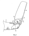
- FIG. 1 is a partially omitted side view of a vehicle seat.
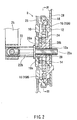
- FIG. 2 is an enlarged cross-sectional view taken along line II-II in FIG. 1 .
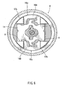
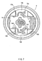
- FIGS. 3-7 are plan views of FIG. 2 viewed along line III-III.
- a rear end of a seat cushion C of a seat is connected to a lower end of a seat back B via a reclining mechanism R.
- the reclining mechanism R can be unlocked by operating an operation lever 25 so that the seat back B can be tilted back and forth around an operating shaft 22.
- the reclining mechanism R includes an outer shell that is constructed from a disk-shaped stationary housing 10 and a disk-shaped rotational housing 12.
- the housings 10 and 12 are oppositely coupled to each other and are relatively rotatably connected by clamping a clip ring 18 that is circumferentially attached thereto ( FIG. 2 ).
- the stationary housing 10 is affixed to a cushion frame 26 of the seat cushion C.
- the rotational housing 12 is affixed to a back frame 28 of the seat back B.
- the housings 10 and 12 define a inner receiving space therebetween that receives an operating cam 14, a pair of slide pawls 16 (16A and 16B), an operating member 20 and a spirally shaped spring 24 therein.
- These construction elements are connected to the operating shaft 22 that passes through central portions of the housings 10 and 12. They are directly connected to the shaft 22 or indirectly connected to the shaft 22 via other members.
- the shaft 22 has opposed ends projecting outwardly through the housings 10 and 12.
- the stationary housing 10 has a receiving opening 10a that passes through the central portion thereof ( FIG. 1 ). Also, as shown in FIG. 3 , the stationary housing 10 has an inner circular recessed portion in which guide grooves 10b and 10c are formed so as to perpendicularly extend vertically and horizontally.
- the operating cam 14 is disposed in the guide grooves 10b.
- the pair of slide pawls 16 (16A and 16B) are disposed in the guide grooves 10c.
- the rotational housing 12 has a receiving opening 12a that passes through the central portion thereof so as to coaxially align with the receiving opening 10a ( FIG. 2 ). Also, as shown in FIG. 3 , the rotational housing 12 has an inner circular recessed portion. The recessed portion has toothed portions constituting ratchets 12b and non-toothed portions 12c. These portions are formed in an outward circumferential surface of the recessed portion. The non-toothed portions 12c are positioned in two locations of the outward circumferential surface of the recessed portion, in which the two locations are angularly spaced apart 180 degrees, so that the ratchets 12b are circumferentially spaced apart by the non-toothed portions 12c. Further, the rotational housing 12 has an outer diameter that can fit within the circular recessed portion of the stationary housing 10 when the rotational housing 12 is coupled to the stationary housing 10.
- the operating cam 14 is a plate having substantially a rectangular shape and has engagement projections 14a and 14b that radially project from around the central portions of opposite longer sides thereof. Also, the operating cam 14 has cam portions 14c and 14d that are respectively formed in the opposite longer sides. They are respectively positioned on both sides of the engagement projections 14a and 14b.
- the operating cam 14 includes a centrally located bore 14e that receives the operating member 20.
- Both of the slide pawls 16 (16A and 16B) are plate members that have the same shape as each other. However, their movement start timings due to the operation of the operating cam 14 are different from one another. Therefore, with regard to the movement of the slide pawls 16, the slide pawls 16A and 16B are separately described. With regard to other points, the slide pawls 16A and 16B are generally described as the slide pawls 16.
- each slide pawl 16 has an arcuate shape.
- a slide pawl 16 has a toothed portion 16a that can engage the ratchet 12b.
- the toothed portion 16a is formed in a pawl top portion that is positioned in a radially outward side when the pawl 16 is assembled into the pawl guide grooves 10c.
- the slide pawl 16 has a pair of right and left contact portions 16b.
- the contact portions 16b are formed in a portion opposite to the pawl top portion, i.e., a portion that is positioned in a radially inward side when the pawl 16 is assembled into the guide grooves 10c.
- Each slide pawl 16 has an engagement recess 16c that is positioned between the contact portions 16b.
- the operating member 20 includes a cylindrical shaft portion 20a and an arm portion 20b that outwardly projects from a circumferencial surface thereof.
- the arm portion 20b engages a part of the bore 14e of the operating cam 14 ( FIG. 3 ).
- a part of the cylindrical shaft portion 20a is positioned in the receiving opening 10a of the stationary housing 10 ( FIG. 2 ).
- a reduced diameter portion 22a of the operating shaft 22 is inserted into the cylindrical shaft portion 20a from the outside of the stationary housing 10.
- An inner circumferential surface of the cylindrical shaft portion 20a and an outer circumferential surface of the reduced diameter portion 22a are shaped to permit transmission of rotational motion therebetween.
- an increased diameter portion 22b of the operating shaft 22 is positioned outside of the stationary housing 10 and has an operation lever 25 attached to its end portion.
- the spring 24 has a spiral shape as described above and functions as a torsion spring between the stationary housing 10 and the operating member 20. That is, the inner end of the spring 24 is connected to the outer circumferential surface of the cylindrical shaft portion 20a and the outer end of the spring 24 is connected to an inner wall portion of the stationary housing 10.
- the operating cam 14 is positioned in the cam guide grooves 10b of the stationary housing 10 so as to slide right and left in FIG. 3 .
- the slide pawls 16 are positioned in the pawl guide grooves 10c of the stationary housing 10 so as to oppose the operating cam 14 and to radially slide without circumferentially moving.
- the engagement projections 14a of the operating cam 14 are respectively positioned in the engagement recesses 16c of the slide pawls 16.
- the cam portions 14c and 14d of the operating cam 14 are positioned so as to contact or to be contactable with the contact portions 16b of the slide pawls 16.
- the operating member 20 is biased counterclockwise in FIG. 3 by the force of the spring 24.
- the operating cam 14 is applied with an actuating force in a leftward direction in FIG. 3 via the arm portion 20b of the operating member 20.
- the operating shaft 22 is rotated about its axis, the operating member 20 moves clockwise in FIG. 3 against the force of the spring 24.
- the operating cam 14 is applied with an actuating force in a rightward direction in FIG. 3 via the arm portion 20b.
- FIG. 3 shows an unlocking or free condition of the reclining mechanism R, i.e., a condition in which the rotational housing 12 can rotate.
- the slide pawls 16 are positioned such that the respective toothed portions 16a faces the non-toothed portions 12c of the rotational housing 12.
- the operating shaft 22 is not applied with a rotational operating force so that the operating cam 14 is applied with the actuating force in a leftward direction in FIG. 2 by the force of the spring 24.
- the cam portions 14c of the operating cam 14 contact the contact portions 16b of the slide pawl 16A that is positioned at the upper side in FIG. 2 , thereby radially outwardly forcing the slide pawl 16A.
- the slide pawl 16A is radially restrictively positioned while the toothed portion 16a contacts the non-toothed portion 12c of the rotational housing 12. Therefore, the operating cam 14 in this condition is applied with a reactive force from the slide pawl 16A so as to be retained by wall surfaces A, positioned on one side (the lower side in FIG. 3 ) of the cam guide grooves 10b. In other words, the operating cam 14 radially outwardly forces the slide pawl 16A by utilizing the wall surfaces A of the cam guide grooves 10b as supporting points. Further, in this condition a narrow clearance is formed between wall surfaces positioned on the opposite side (the upper side in FIG. 3 ) of the cam guide grooves 10b and the operating cam 14. In addition, the cam portions 14d of the operating cam 14 are not contacting the contact portions 16b of the slide pawl 16B that is positioned at the lower side of FIG. 2 .
- the rotational housing 12 rotates clockwise in the configuration shown in FIG. 3 . Due to this rotation, as shown in FIG. 4 , the ratchets 12b are shifted so as to be opposite to the toothed portions 16a of the slide pawls 16.
- the operating cam 14 moves leftwardly by the force of the spring 24 so that the cam portions 14c push the contact portions 16b of the slide pawl 16A. Therefore, the operating cam 14 moves the slide pawl 16A radially outwardly by utilizing the wall surfaces A of the cam guide grooves 10b as supporting points.
- FIG. 4 illustrates a condition immediately before the toothed portion 16a of the slide pawl 16A engages the ratchet 12b. Further, in this condition, the cam portions 14d of the operating cam 14 are not still contacting the contact portions 16b of the slide pawl 16B, so that the slide pawl 16B is not moved.
- FIG. 5 illustrates a condition in which the toothed portion 16a of the slide pawl 16A engages the ratchet 12b over substantially half of their tooth depth. In this condition, the cam portions 14d of the operating cam 14 begin to contact the contact portions 16b of the slide pawl 16B.
- the slide pawl 16B follows the slide pawl 16A so as to begin to move radially outwardly. And due to the difference of the shape of the cam portions 14c and 14d, as shown in FIG. 6 , the toothed portion 16a of the slide pawl 16B completely engages the ratchet 12b just before the toothed portion 16a of the slide pawl 16A completely engages the ratchet 12b.
- the cam portions 14d run on the contact portions 16b of the slide pawl 16B. That is, after this condition, the supporting points of the operating cam 14 shift from the wall surfaces A of the cam guide grooves 10b to the contact portions 16b of the slide pawl 16B. Therefore, the operating cam 14 then moves the slide pawl 16A radially outwardly by utilizing the contact portions 16b as the supporting points so that the corresponding toothed portion 16a completely engages the ratchet 12b. Consequently, the reclining mechanism R is configured in a locking condition in which the relative rotation of the housings 10 and 12 is prevented. This locking condition can be maintained by the force of the spring 24.
- the slide pawls 16 are moved from their free positions to their locking positions in which they engage the ratchets 12b, if the slide pawl 16A completely engaged the ratchet 12b at the time shown in FIG. 5 , the operating cam 14 could not be moved further leftwardly. This may preclude the engagement of the slide pawl 16B to the ratchet 12b. Consequently, the slide pawl 16B is constructed to completely engage the ratchet 12b before the slide pawl 16A (having the preceding movement start timing toward the locking position) completely engages the ratchet 12b. Further, the slide pawl 16A is constructed to finally completely engage the ratchet 12b so that the slide pawls 16A and 16B can appropriately engage the ratchets 12b.
- the operating shaft 22 and the operating member 20 are rotated clockwise against the force of the spring 24 by operating the operation lever 25.
- the operating cam 14 moves in the rightward direction in the drawings so that the engagement projections 14a and 14b respectively enter the engagement recesses 16c of the slide pawls 16.
- the slide pawls 16 are drawn back radially inwardly so that the respective toothed portions 16a are disengaged from the ratchets 12b, thereby permitting relative rotation of the housings 10 and 12.
- FIG. 8 is a plan view corresponding to FIG. 3 and illustrates a reclining mechanism according to the second embodiment.
- the present invention is applied to a reclining mechanism R that includes a rotating-type operating cam and three slide pawls.
- the circular plate-shaped operating cam 114 is positioned in the stationary housing 10 so as to rotate around an axis of an operating shaft 122.
- the three slide pawls 116 (116A, 116B, 116C) are positioned in pawl guide grooves of the stationary housing 10 so as to radially slide without circumferentially moving.
- Each of cam portions 114c, 114d and 114e formed in an outer circumferential surface of the operating cam 114 are positioned so as to contact or to be contactable with contact portions 116b of each of the slide pawls 116.
- the operating cam 114 is rotatably supported about bearing openings 13 of the housings 10 and 12 and is biased in a counterclockwise direction in FIG. 8 by the force of a spring (not shown).
- FIG. 8 shows an unlocking or free condition of the reclining mechanism R, i.e., a condition in which the housings 10 and 12 can rotate relative to each other.
- the cam portions 114c of the operating cam 114 contact the contact portions 116b of the slide pawl 116A, thereby radially outwardly forcing the slide pawl 116A.
- the slide pawl 116A is radially restrictively positioned while its toothed portion 116a contacts the non-toothed portion of the ratchets 12b. Therefore, the operating cam 114 is applied with a reactive force from the slide pawl 116A so as to be retained by a portion of the inner circumferential surfaces of the bearing openings 13.
- the operating cam 114 radially outwardly forces the slide pawl 116A by utilizing the inner circumferential surfaces of the bearing openings 13 as supporting points. Further, the cam portions 114d and 114e of the operating cam 114 are not contacting the contact portions 116b of the slide pawls 116B and 116C.
- the ratchets 12b are shifted so as to be opposite to the toothed portions 116a of the respective slide pawls 116.
- the operating cam 114 rotates counterclockwise by the spring force so that the cam portions 114c push the contact portions 116b of the slide pawl 116A. Therefore, the operating cam 114 radially outwardly moves the slide pawl 116A by utilizing the inner circumferential surfaces of the bearing openings 13 as the supporting points.
- the supporting points of the operating cam 114 shift from the inner circumferential surfaces of the bearing openings 13 to the contact portions 116b of the slide pawls 116B and 116C. Therefore, the operating cam 114 then radially outwardly moves the slide pawl 116A by utilizing the contact portions 116b as supporting points, so that the corresponding toothed portion 116a completely engages the ratchet 12b. Consequently, the reclining mechanism R is configured in a locking condition in which the relative rotation of the housings 10 and 12 is limited.
- the operating cam 144 is rotated clockwise against the spring force, together with the operating shaft 122. Due to the functions of a plate member (not shown) that integrally rotates with the operating cam 144, each of the slide pawls 116 moves radially inwardly so that the respective toothed portions 116a are disengaged from the ratchets 12b. Further, with regard to the reclining mechanism R shown in the second embodiment, four or more slide pawls may be used.
- the first and second embodiments are described with regard to the reclining mechanism R in which the sliding-type pawls 16 and 116 are used.
- the reclining mechanism R may be a reclining mechanism having rotary pawls that are rotatable from a free position to a locking position.
- the first and second embodiments describe the case in which the movement start timing of at least one of the pawls precedes the movement start timing of the other of the pawls.
- the spring force can converge on one of the slide pawls.
- the engagement (locking) force between one of the slide pawls and the ratchet can be increased without increasing the spring force.
- the other slide pawls can completely engage the corresponding ratchets 12b before the slide pawl having the preceding movement start timing completely engages the ratchet 12b. Due to this order of engagement, the operating cam may be prevented from being unable to rotate or slide so that all of the slide pawls can engage the ratchets 12b.
Landscapes
- Engineering & Computer Science (AREA)
- Aviation & Aerospace Engineering (AREA)
- Transportation (AREA)
- Mechanical Engineering (AREA)
- Chairs For Special Purposes, Such As Reclining Chairs (AREA)
- Seats For Vehicles (AREA)
Claims (13)
- Ein Rückenlehnenmechanismus (R), der einen Aufbau aufweist, in dem eine Vielzahl von Klinken (16; 116) in einem Paar von Gehäusen (10, 12) aufgenommen sind, die relativ zueinander drehbar miteinander verbunden sind, wobei jede dieser Klinken (16; 116) am Drehen relativ zu einem der Gehäuse (10, 12) gehindert ist und mit einer Sperrklinke (12b) in Eingriff bringbar ist, die in dem anderen der Gehäuse (10, 12) gebildet ist, wobei jede der Klinken (16; 116) durch eine Federkraft aus einer freien Position, in welcher die relative Drehung der Gehäuse (10, 12) zugelassen wird, in eine Verriegelungsposition bewegt wird, in welcher die relative Drehung der Gehäuse (10, 12) mittels des Eingriffs der Klinken (16; 116) in die Sperrklinke (12b) verhindert wird, wobei sich mindestens eine der Klinken (16; 116) vor der anderen der Klinken (16; 116) bewegt, wenn sich jede der Klinken (16; 116) aus der freien Position in die Verriegelungsposition bewegt.
- Der Rückenlehnenmechanismus (R) nach Anspruch 1, wobei ein Betätigungsnocken (14; 114), der durch die Federkraft betätigt wird, in den Gehäusen (10, 12) aufgenommen ist, und wobei der Zeitpunkt der Bewegung jeder der Klinken (16; 116) bei der Benutzung durch die Form von Nockenabschnitten des Betätigungsnockens (14; 114) definiert ist.
- Rückenlehnenmechanismus (R) nach Anspruch 1, wobei ein Betätigungsnocken (14; 114) in den Gehäusen (10, 12) aufgenommen ist, jede der Klinken (16; 116) einen gezahnten Abschnitt (16a; 116a) aufweist, der dazu fähig ist, in die Sperrklinke (12b) einzugreifen, und einen Kontaktabschnitt (16b; 116b), der dem gezahnten Abschnitt (16a; 116a) gegenüber positioniert ist, wobei der Betätigungsnocken (14; 114) Nockenabschnitte (14c, 14d; 114c, 114d, 114e) aufweist, die jeweils getrennt mit den Kontaktabschnitten (16b; 116b) der jeweiligen Klinken (16; 116) interagieren können, wobei die jeweiligen Nockenabschnitte (14c, 14d; 114c, 114d, 114e) separat mit den Kontaktabschnitten (16b; 116b) der jeweiligen Klinken (16; 116) interagieren, wenn der Betätigungsnocken (14; 114) durch eine vorab festgelegte Federkraft so betätigt wird, dass jede der Klinken (16; 116) aus der freien Position, in welcher die relative Drehung der Gehäuse (10, 12) erlaubt ist, in die Verriegelungsposition bewegt wird, in welcher die relative Drehung der Gehäuse (10, 12) durch den Eingriff der gezahnten Abschnitte (16a; 116a) in die Sperrklinke (12b) verhindert wird, wobei die jeweiligen Nockenabschnitte (14c, 14d; 114c, 114d, 114e) des Betätigungsnockens (14; 114) so geformt sind, dass sich mindestens eine der Klinken (16; 116) vor der anderen der Klinken (16; 116) bewegt.
- Rückenlehnenmechanismus (R) nach Anspruch 3, wobei jeder der Nockenabschnitte (14c, 14d; 114c, 114d, 114e) des Betätigungsnockens (14; 114) so geformt ist, dass, wenn sich eine der Klinken (16; 116) aus der freien Position in die Verriegelungsposition bewegt, die andere der Klinken (16; 116) beginnt, sich so zu bewegen, dass der gezahnte Abschnitt (16a; 116a) in die Sperrklinke (12b) eingreift, bevor der gezahnte Abschnitt (16a; 116a) einer der Klinken (16; 116) vollständig in die Sperrklinke (12b) eingreift.
- Rückenlehnenmechanismus (R) nach Anspruch 3, wobei eine Reaktionskraft von einer der Klinken (16; 116) durch ein Führungsteil aufgenommen wird, welches den Betätigungsnocken (14; 114) operational führt, wenn eine der Klinken (16; 116) durch die Betätigung des Betätigungsnockens (14; 114) zuerst damit beginnt, sich zu bewegen, und wobei die andere der Klinken (16; 116) beginnt, sich zu bewegen, bevor die Bewegung der einen der Klinken (16; 116) abgeschlossen ist, sodass eine Reaktionskraft von der anderen der Klinken (16; 116) durch die eine der Klinken (16; 116) aufgenommen wird.
- Rückenlehnenmechanismus (R) nach Anspruch 3, wobei die Klinken (16; 116) eine Vielzahl von Gleitklinken umfassen, wobei jede dieser Gleitklinken radial gleitfähig ist, während sie daran gehindert ist, sich relativ zu einem der Gehäuse (10, 12) zu bewegen.
- Rückenlehnenmechanismus (R) nach Anspruch 6, wobei der Betätigungsnocken (14) ein Nocken vom Gleittyp ist, und wobei die Bewegung einer der Gleitklinken durch Nutzung eines Kontaktabschnitts einer Seitenoberfläche gegenüber dem Nockenabschnitt (14c, 14d) des Betätigungsnockens (14) durchgeführt wird, der mit dem Kontaktabschnitt (16b) der Gleitklinke und einer Führungsnut (10b) der Wandoberfläche des Gehäuses (10, 12) interagiert, welche den Betätigungsnocken (14) als Lagerpunkt gleitfähig führt.
- Rückenlehnenmechanismus (R) nach Anspruch 6, wobei der Betätigungsnocken (114) ein Nocken vom drehenden Typ ist, und wobei die Bewegung einer der Gleitklinken (116) durch Verwenden eines Kontaktabschnitts des Betätigungsnockens (114) und innerer Umfangsoberflächen von Lageröffnungen (13) der Gehäuse (10, 12) erreicht wird, welche den Betätigungsnocken (114) als Lagerpunkt drehbar lagern.
- Rückenlehnenmechanismus (R) nach Anspruch 6, wobei jeder der Nockenabschnitte des Betätigungsnockens (14; 114) so geformt ist, dass, wenn sich eine der Gleitklinken (16; 116) aus der freien Position in die Verriegelungsposition bewegt, die andere der Klinken (16; 116) beginnt, sich so zu bewegen, dass sie in den gezahnten Abschnitt (16a; 116a) mit der Sperrklinke (12b) eingreift, bevor der gezahnte Abschnitt (16a; 116a) einer der Gleitklinken (16; 116) vollständig in die Sperrklinke (12b) eingreift.
- Rückenlehnenmechanismus (R) nach Anspruch 6, wobei, wenn eine der Gleitklinken (16; 116) zuerst beginnt, sich durch die Betätigung des Betätigungsnockens (14; 114) zu bewegen, eine Reaktionskraft von einer der Gleitklinken (16; 116) durch ein Führungsteil aufgenommen wird, welches den Betätigungsnocken (14; 114) operational führt, und wobei die andere aus den Gleitklinken (16; 116) damit beginnt, sich vor dem Abschluss der Bewegung der einen aus den Gleitklinken (16; 116) so zu bewegen, dass eine Reaktionskraft von der anderen der Gleitklinken (16; 116) jeweils von den Gleitklinken (16; 116) gegenseitig aufgenommen wird.
- Rückenlehnenmechanismus (R) nach Anspruch 3, wobei die jeweiligen Nockenabschnitte des Betätigungsnockens (14; 114) so geformt sind, dass der Bewegungsstartzeitpunkt einer der Klinken (16; 116) dem Bewegungsstartzeitpunkt der anderen der Klinken (16; 116) vorausgeht.
- Rückenlehnenmechanismus (R) nach Anspruch 11, wobei jeder der Nockenabschnitte des Betätigungsnockens (14; 114) so geformt ist, dass, wenn jede der Gleitklauen (16; 116) aus der freien Position in die Verriegelungsposition bewegt wird, die andere der Klinken (16; 116) rechtzeitig damit beginnt, sich so zu bewegen, dass sie in den gezahnten Abschnitt (16a; 116a) in die Sperrklinke (12b) eingreift, bevor der gezahnte Abschnitt (16a; 116a) einer der Klinken (16; 116) vollständig in die Sperrklinke (12b) eingreift.
- Rückenlehnenmechanismus (R) nach Anspruch 11, wobei eine Reaktionskraft von einer der Klinken (16; 116) durch ein Führungsteil aufgenommen wird, welches den Betätigungsnocken (14; 114) operational führt, wenn eine der Klinken (16; 116) als erste damit beginnt, sich zu bewegen, indem sie den Betätigungsnocken (14; 114) betätigt, und wobei die andere der Klinken (16; 116) vor dem Abschluss der Bewegung der einen der Klinken (16; 116) damit beginnt, sich so zu bewegen, dass eine Reaktionskraft von der anderen der Klinken (16; 116) jeweils gegenseitig von den Klinken (16; 116) aufgenommen wird.
Applications Claiming Priority (3)
| Application Number | Priority Date | Filing Date | Title |
|---|---|---|---|
| JP2002226320 | 2002-08-02 | ||
| JP2002226320 | 2002-08-02 | ||
| PCT/JP2003/009700 WO2004012560A1 (ja) | 2002-08-02 | 2003-07-30 | リクライニング装置及びそのロック方法 |
Publications (3)
| Publication Number | Publication Date |
|---|---|
| EP1552769A1 EP1552769A1 (de) | 2005-07-13 |
| EP1552769A4 EP1552769A4 (de) | 2007-05-02 |
| EP1552769B1 true EP1552769B1 (de) | 2009-06-24 |
Family
ID=31492185
Family Applications (1)
| Application Number | Title | Priority Date | Filing Date |
|---|---|---|---|
| EP03766666A Expired - Lifetime EP1552769B1 (de) | 2002-08-02 | 2003-07-30 | Lehnvorrichtung und verfahren zum arretieren der vorrichtung |
Country Status (5)
| Country | Link |
|---|---|
| US (1) | US7222919B2 (de) |
| EP (1) | EP1552769B1 (de) |
| JP (1) | JP4349284B2 (de) |
| DE (1) | DE60328118D1 (de) |
| WO (1) | WO2004012560A1 (de) |
Families Citing this family (23)
| Publication number | Priority date | Publication date | Assignee | Title |
|---|---|---|---|---|
| FR2869848B1 (fr) * | 2004-05-04 | 2006-07-21 | Faurecia Sieges Automobile | Mecanisme d'articulation de siege de vehicule et siege de vehicule equipe d'un tel mecanisme d'articulation |
| JP4736726B2 (ja) * | 2005-11-10 | 2011-07-27 | トヨタ紡織株式会社 | リクライニング装置 |
| US7517021B2 (en) * | 2006-09-12 | 2009-04-14 | Lear Corporation | Reclining mechanism for vehicle seats |
| US20080073961A1 (en) * | 2006-09-12 | 2008-03-27 | Lear Corporation | Reclining mechanism for vehicle seats |
| JP5126227B2 (ja) * | 2007-06-01 | 2013-01-23 | トヨタ紡織株式会社 | 継手装置 |
| US8267476B2 (en) * | 2007-11-09 | 2012-09-18 | Toyota Boshoku Kabushiki Kaisha | Vehicle seat reclining device |
| US7677666B2 (en) | 2008-01-09 | 2010-03-16 | Bae Industries, Inc. | Disc recliner assembly incorporated into a seatback/seat base pivot associated with a vehicle seat |
| WO2009091980A1 (en) | 2008-01-17 | 2009-07-23 | Fisher Dynamics Corporation | Round recliner mechanism |
| JP2009247394A (ja) * | 2008-04-01 | 2009-10-29 | Delta Kogyo Co Ltd | シートのリクライニング装置 |
| JP5315757B2 (ja) | 2008-04-08 | 2013-10-16 | トヨタ紡織株式会社 | 車両用シートの連結装置 |
| WO2010101569A1 (en) * | 2009-03-05 | 2010-09-10 | Lear Corporation | Reclining mechanism for vehicle seats |
| FR2972972B1 (fr) * | 2011-03-22 | 2013-04-26 | Faurecia Sieges Automobile | Systeme d'articulation et siege de vehicule comportant un tel systeme d'articulation |
| JP5770601B2 (ja) * | 2011-10-31 | 2015-08-26 | 富士機工株式会社 | シートリクライニング装置 |
| DE102012008822A1 (de) | 2012-05-07 | 2013-11-07 | GM Global Technology Operations LLC (n.d. Ges. d. Staates Delaware) | Verstellvorrichtung, Kraftfahrzeugsitz, Kraftfahrzeug und Verfahren hierzu |
| US9296315B2 (en) | 2013-02-26 | 2016-03-29 | Fisher & Company, Incorporated | Recliner mechanism with backdriving feature |
| KR101422418B1 (ko) * | 2013-10-31 | 2014-07-22 | 주식회사다스 | 자동차 시트의 리클라이너 |
| US9902297B2 (en) | 2014-06-11 | 2018-02-27 | Fisher & Company, Incorporated | Latch mechanism with locking feature |
| US10220729B2 (en) | 2015-09-24 | 2019-03-05 | Faurecia Automotive Seating, Llc | Seat position-sensing system |
| JP6682300B2 (ja) * | 2016-03-04 | 2020-04-15 | シロキ工業株式会社 | シートリクライニング装置 |
| WO2017180520A1 (en) | 2016-04-11 | 2017-10-19 | Faurecia Automotive Seating, Llc | Recliner for a vehicle seat |
| US10351020B2 (en) | 2016-09-29 | 2019-07-16 | Faurecia Automotive Seating, Llc | Recliner for a vehicle seat |
| US10414296B2 (en) | 2016-12-12 | 2019-09-17 | Faurecia Automotive Seating, Llc | Recliner for a vehicle seat |
| US10611273B2 (en) | 2017-10-09 | 2020-04-07 | Faurecia Automotive Seating, Llc | Recliner system for a vehicle seat |
Family Cites Families (12)
| Publication number | Priority date | Publication date | Assignee | Title |
|---|---|---|---|---|
| FR2462127A1 (fr) * | 1979-08-02 | 1981-02-13 | Faure Bertrand | Perfectionnements aux dispositifs d'articulation des dossiers de siege |
| FR2599684B1 (fr) * | 1986-06-06 | 1990-02-02 | Cousin Cie Ets A & M Freres | Articulations pour dossier de siege de vehicule ou applications analogues comportant des grains a guidages asymetriques |
| JPH02128707A (ja) * | 1988-11-09 | 1990-05-17 | Mitsui Mining & Smelting Co Ltd | シート等の調節装置 |
| JP3080139B2 (ja) * | 1995-11-08 | 2000-08-21 | 池田物産株式会社 | 内歯式リクライニングデバイス |
| JP4265024B2 (ja) | 1998-06-22 | 2009-05-20 | トヨタ紡織株式会社 | リクライニング装置 |
| FR2790230B1 (fr) * | 1999-02-25 | 2002-05-24 | Faure Bertrand Equipements Sa | Mecanisme d'articulation pour siege de vehicule et siege equipe d'un tel mecanisme |
| JP4457434B2 (ja) * | 1999-08-02 | 2010-04-28 | トヨタ紡織株式会社 | リクライニング装置 |
| JP2001149160A (ja) | 1999-11-25 | 2001-06-05 | Ikeda Bussan Co Ltd | リクライニング装置 |
| JP3804431B2 (ja) * | 2000-10-13 | 2006-08-02 | トヨタ紡織株式会社 | リクライニング装置 |
| US7097251B2 (en) * | 2000-10-13 | 2006-08-29 | Toyota Boshoku Kabushiki Kaisha | Reclining device for a seat |
| JP3767387B2 (ja) * | 2001-01-23 | 2006-04-19 | トヨタ紡織株式会社 | リクライニング装置 |
| JP4770067B2 (ja) * | 2001-06-07 | 2011-09-07 | トヨタ紡織株式会社 | シートリクライニング装置 |
-
2003
- 2003-07-30 JP JP2004525802A patent/JP4349284B2/ja not_active Expired - Fee Related
- 2003-07-30 DE DE60328118T patent/DE60328118D1/de not_active Expired - Lifetime
- 2003-07-30 EP EP03766666A patent/EP1552769B1/de not_active Expired - Lifetime
- 2003-07-30 WO PCT/JP2003/009700 patent/WO2004012560A1/ja not_active Ceased
- 2003-07-30 US US10/523,275 patent/US7222919B2/en not_active Expired - Fee Related
Also Published As
| Publication number | Publication date |
|---|---|
| JPWO2004012560A1 (ja) | 2006-09-21 |
| EP1552769A4 (de) | 2007-05-02 |
| DE60328118D1 (de) | 2009-08-06 |
| US20050264076A1 (en) | 2005-12-01 |
| JP4349284B2 (ja) | 2009-10-21 |
| WO2004012560A1 (ja) | 2004-02-12 |
| EP1552769A1 (de) | 2005-07-13 |
| US7222919B2 (en) | 2007-05-29 |
Similar Documents
| Publication | Publication Date | Title |
|---|---|---|
| EP1552769B1 (de) | Lehnvorrichtung und verfahren zum arretieren der vorrichtung | |
| EP2326531B1 (de) | Plattenneiger mit reduziertem spiel | |
| US6609756B2 (en) | Seat reclining device for vehicle | |
| US8042669B2 (en) | Rocker-type selectable one-way clutch with neutral position | |
| EP2062504B1 (de) | Neigungsversteller für einen Sitz | |
| US6007152A (en) | Seat reclining mechanism for vehicles | |
| JP5609889B2 (ja) | ロック装置 | |
| US10112507B2 (en) | Seat reclining apparatus | |
| US7823978B2 (en) | Reclining device | |
| JP4595256B2 (ja) | シートリクライニング装置 | |
| JP4896891B2 (ja) | 車両シート用取り付け具 | |
| US9079517B2 (en) | Dual cam recliner | |
| JP2009066410A (ja) | 自動車シートチルト調節機構 | |
| KR100871745B1 (ko) | 리클라이닝 장치 | |
| JP2008525064A5 (de) | ||
| EP3381743A1 (de) | Sitzneigungsvorrichtung | |
| JP4568762B2 (ja) | 車両シート用取り付け具 | |
| JP2008525065A5 (de) | ||
| JP4736726B2 (ja) | リクライニング装置 | |
| JP4125911B2 (ja) | 可変レバータンブラー錠 | |
| JP4763330B2 (ja) | リクライニング装置 | |
| JP4255811B2 (ja) | リクライニング装置 | |
| JP4824945B2 (ja) | リクライニング装置 | |
| JP2003019052A (ja) | リクライニング装置 | |
| JP7633515B2 (ja) | リクライニング装置 |
Legal Events
| Date | Code | Title | Description |
|---|---|---|---|
| PUAI | Public reference made under article 153(3) epc to a published international application that has entered the european phase |
Free format text: ORIGINAL CODE: 0009012 |
|
| 17P | Request for examination filed |
Effective date: 20050211 |
|
| AK | Designated contracting states |
Kind code of ref document: A1 Designated state(s): AT BE BG CH CY CZ DE DK EE ES FI FR GB GR HU IE IT LI LU MC NL PT RO SE SI SK TR |
|
| RBV | Designated contracting states (corrected) |
Designated state(s): DE FR |
|
| A4 | Supplementary search report drawn up and despatched |
Effective date: 20070402 |
|
| 17Q | First examination report despatched |
Effective date: 20071219 |
|
| GRAJ | Information related to disapproval of communication of intention to grant by the applicant or resumption of examination proceedings by the epo deleted |
Free format text: ORIGINAL CODE: EPIDOSDIGR1 |
|
| GRAP | Despatch of communication of intention to grant a patent |
Free format text: ORIGINAL CODE: EPIDOSNIGR1 |
|
| GRAP | Despatch of communication of intention to grant a patent |
Free format text: ORIGINAL CODE: EPIDOSNIGR1 |
|
| GRAS | Grant fee paid |
Free format text: ORIGINAL CODE: EPIDOSNIGR3 |
|
| GRAA | (expected) grant |
Free format text: ORIGINAL CODE: 0009210 |
|
| AK | Designated contracting states |
Kind code of ref document: B1 Designated state(s): DE FR |
|
| REF | Corresponds to: |
Ref document number: 60328118 Country of ref document: DE Date of ref document: 20090806 Kind code of ref document: P |
|
| PLBE | No opposition filed within time limit |
Free format text: ORIGINAL CODE: 0009261 |
|
| STAA | Information on the status of an ep patent application or granted ep patent |
Free format text: STATUS: NO OPPOSITION FILED WITHIN TIME LIMIT |
|
| 26N | No opposition filed |
Effective date: 20100325 |
|
| PGFP | Annual fee paid to national office [announced via postgrant information from national office to epo] |
Ref country code: DE Payment date: 20140724 Year of fee payment: 12 |
|
| PGFP | Annual fee paid to national office [announced via postgrant information from national office to epo] |
Ref country code: FR Payment date: 20140708 Year of fee payment: 12 |
|
| REG | Reference to a national code |
Ref country code: DE Ref legal event code: R119 Ref document number: 60328118 Country of ref document: DE |
|
| PG25 | Lapsed in a contracting state [announced via postgrant information from national office to epo] |
Ref country code: DE Free format text: LAPSE BECAUSE OF NON-PAYMENT OF DUE FEES Effective date: 20160202 |
|
| REG | Reference to a national code |
Ref country code: FR Ref legal event code: ST Effective date: 20160331 |
|
| PG25 | Lapsed in a contracting state [announced via postgrant information from national office to epo] |
Ref country code: FR Free format text: LAPSE BECAUSE OF NON-PAYMENT OF DUE FEES Effective date: 20150731 |