EP1552780A2 - Reinigungsgerät - Google Patents
Reinigungsgerät Download PDFInfo
- Publication number
- EP1552780A2 EP1552780A2 EP04029378A EP04029378A EP1552780A2 EP 1552780 A2 EP1552780 A2 EP 1552780A2 EP 04029378 A EP04029378 A EP 04029378A EP 04029378 A EP04029378 A EP 04029378A EP 1552780 A2 EP1552780 A2 EP 1552780A2
- Authority
- EP
- European Patent Office
- Prior art keywords
- cleaning
- handle
- pumping
- cleaning device
- housing
- Prior art date
- Legal status (The legal status is an assumption and is not a legal conclusion. Google has not performed a legal analysis and makes no representation as to the accuracy of the status listed.)
- Granted
Links
Images

Classifications
-
- A—HUMAN NECESSITIES
- A47—FURNITURE; DOMESTIC ARTICLES OR APPLIANCES; COFFEE MILLS; SPICE MILLS; SUCTION CLEANERS IN GENERAL
- A47L—DOMESTIC WASHING OR CLEANING; SUCTION CLEANERS IN GENERAL
- A47L1/00—Cleaning windows
- A47L1/06—Hand implements
- A47L1/08—Hand implements with provision for supplying liquids, e.g. cleaning agents
-
- A—HUMAN NECESSITIES
- A47—FURNITURE; DOMESTIC ARTICLES OR APPLIANCES; COFFEE MILLS; SPICE MILLS; SUCTION CLEANERS IN GENERAL
- A47L—DOMESTIC WASHING OR CLEANING; SUCTION CLEANERS IN GENERAL
- A47L13/00—Implements for cleaning floors, carpets, furniture, walls, or wall coverings
- A47L13/10—Scrubbing; Scouring; Cleaning; Polishing
- A47L13/20—Mops
- A47L13/22—Mops with liquid-feeding devices
Definitions
- the present invention relates to a cleaning device for flat surfaces, in particular for household use, with a cleaning plate containing at least one Handle is connected to a pumping device for conveying a cleaning liquid from a tank, an arranged on the handle pumping and a above
- a cleaning plate arranged housing Such devices will be very happy for cleaning windows or other flat, smooth surfaces in the kitchen and used in the bathroom area. Another application is the cleaning of vehicle windows. Also for the cleaning of floors find these devices use.
- German utility model 85 29 619 is a hand-held device for cleaning Surfaces, in particular disc known, in which a cleaning liquid receiving container is integrated in the handle part and this cleaning fluid over a pump spray system can be sprayed on the surface to be cleaned.
- a cleaning liquid receiving container is integrated in the handle part and this cleaning fluid over a pump spray system can be sprayed on the surface to be cleaned.
- one is Cleaning part arranged with a sponge-like cleaning element on the handle.
- this device is only suitable for cleaning surfaces that are in the Arm-grip area and there is no cleaning plate provided for wiping larger areas is suitable.
- the object of the invention is to provide a cleaning device for flat surfaces, with the targeted cleaning surface can be supplied with cleaning fluid and with which both areas of application can be covered, namely in the immediate Arm-grip area as well as at remote floor areas.
- a spray head is provided on the housing of the cleaning device and via the pump operation, the spray head gives targeted cleaning fluid on a surface to be cleaned adjacent to the cleaning plate. The user can thus deliver targeted contaminants on the surface to be cleaned.
- the spray head for a simple construction of the cleaning device in a receptacle held between two housing halves.
- a pressure in the pressure chamber can be generated.
- the tank is between the cleaning plate and the housing arranged above it and thus largely arranged concealed and protected. Furthermore, a balanced handling achieved in that the tank with attached pumping device is arranged directly behind the cleaning plate, ie at the to be cleaned Surface support can take place.
- a first handle is integrally formed on the housing and this handle with a receptacle for a second, arranged on an extension handle is provided, both Handles each equipped with a pumping action acting on the pumping device are.
- the user can thus choose freely, in which version he the cleaning device wants to use, for example, as a manoeuvrable handheld device for low Windows, mirrors, shower cabins or with extension handle for high Windows, flat surfaces in the bathroom and floors.
- the pumping operation of the first handle via a piston lever and the pumping operation of the second handle over a piston rod connected to the pumping device
- the piston rod be guided in a tube and an adapter for connection to the pumping device be provided.
- the pumping device with its piston side to the end arranged the handle, so that a double admission both over the Handle of the first handle, so when used as a compact handset, as also an actuation via a piston rod to a spray lever in a second Handle at the end of the stem extension is possible.
- a rubber lip for scraping Liquid set Preferably, on the cleaning plate, a rubber lip for scraping Liquid set, so that the cleaning device is also particularly good for the Use window cleaning.
- the cleaning device 1 comprises a hand wiper 2 with a first handle 3, which receives in a receptacle 4 an extension 5 with a second handle 6.
- the handle 3 is connected to a cleaning plate 7 and includes a multi-part housing 18, 20 in which a pumping device 8, a tank 9 and a Spray head 10 are added.
- the pumping device 8 is a pumping operation in the form of a handle lever 11th triggered by a piston lever 12.
- the cleaning device is used as a hand wiper.
- This extension 5 ends in the handle 6.
- a spray lever 13 is mounted, which acts on a piston rod 14, the over an adapter 15 acts on the pumping device 8.
- the piston rod 14 is over Foam parts 16 in the extension 5 out. These foam pieces 16 act also stiffening, so that the piston rod 14 can be made quite thin.
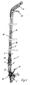
- FIG. 1 the configuration of a cleaning device as a floor and window wiper represents for higher windows
- Fig. 2 shows the cleaning device as a hand wiper.
- the handle 3 is starting from a closed receiving sleeve 17 in Split longitudinally and integrally connected to housing halves 18 and 20. It is on the housing half 18, the receiving sleeve 17 and a half of the cover plate 19th and formed on the other half of the cover plate half 21. Between the cover plate 19 and a bottom plate 21, together forming the cleaning plate 7, is the Tank 9 arranged.
- the tank 9 penetrates with a neck 24, the cover plate 19 and is closed by a fuel cap 25.
- the spray nozzle is in a receptacle 31, which is fixed between the housing halves 18 and 20.
- a clamped between the cover plate 19 and the bottom plate 22 rubber lip 26 serves to remove liquid on even surfaces.
- the rubber lip 26 is protrudes forward and can by appropriate pivoting of the cleaning device be brought into contact with a surface.
- the cover plate halves 20 and 21 are integrally formed with respect to the bottom plate 21 protruding cloth clamps 27 provided for fixing various Serve wipes.
- the tank 9 is connected via a piece of tubing 28 with the pumping device 8 and via a Valve 29 is connected to the spray head 10.
Landscapes
- Cleaning By Liquid Or Steam (AREA)
- Vehicle Cleaning, Maintenance, Repair, Refitting, And Outriggers (AREA)
- Nozzles (AREA)
Abstract
Description
- Fig. 1
- Einen Längsschnitt durch ein Reinigungsgerät mit einer Verlängerung mit zweitem Handgriff (vereinfacht dargestellt), und
- Fig. 2
- das Reinigungsgerät der Figur 1 als Handwischers mit einer Aufnahme für eine Verlängerung.
Claims (9)
- Reinigungsgerät für plane Flächen, insbesondere für den Haushaltsbereich, mit einer Reinigungsplatte (7), die mit mindestens einem Griff (3, 6) verbunden ist, einer Pumpeinrichtung (8) zur Förderung einer Reinigungsflüssigkeit aus einem Tank (9), einer an dem Griff (3, 6) angeordneten Pumpbetätigung (11, 13) und einem oberhalb der Reinigungsplatte (7) angeordnetem Gehäuse (18, 20), dadurch gekennzeichnet, dass an dem Gehäuse (18, 20) ein Sprühkopf (10) vorgesehen ist und über die Pumpbetätigung (11, 13) der Sprühkopf (10) gezielt Reinigungsflüssigkeit auf eine zu reinigende Fläche benachbart zu der Reinigungsplatte (7) abgibt.
- Reinigungsgerät nach Anspruch 1, dadurch gekennzeichnet, dass der Sprühkopf (10) in einer Aufnahme zwischen zwei Gehäusehälften (18, 20) gehalten ist.
- Reinigungsgerät nach Anspruch 1 oder 2, dadurch gekennzeichnet, dass die Pumpeinrichtung (8) eine Druckkammer aufweist und zum Aussprühen der Reinigungsflüssigkeit über die Pumpbetätigung (11, 13) ein Druck in der Druckkammer erzeugbar ist.
- Reinigungsgerät nach einen der Ansprüche 1 bis 3, dadurch gekennzeichnet, dass der Tank (9) zwischen der Reinigungsplatte (7) und dem darüber angeordnetem Gehäuse (18, 20) gehalten ist.
- Reinigungsgerät nach einen der Ansprüche 1 bis 4, dadurch gekennzeichnet, dass ein erster Griff (3) an dem Gehäuse (18, 20) angeformt ist und dieser Griff (3) mit einer Aufnahme (4) für einen zweiten, an einer Verlängerung (5) angeordneten Griff (6) versehen ist, wobei beide Griffe (3, 6) jeweils mit einer auf die Pumpeinrichtung wirkenden Pumpbetätigung (11, 13) ausgestattet sind.
- Reinigungsgerät nach einen der Ansprüche 1 bis 5, dadurch gekennzeichnet, dass an dem Gehäuse (18, 20) an gegenüberliegenden Seiten hervorstehende Tuchklemmen (27) zur Befestigung eines Wischtuches angeformt sind.
- Reinigungsgerät nach einem der Ansprüche 1 bis 6, dadurch gekennzeichnet, dass die Pumpbetätigung (11) des ersten Handgriffes (3) über einen Kolbenhebel (12) und die Pumpbetätigung (13) des zweiten Handgriffes (6) über eine Kolbenstange (14) mit der Pumpeinrichtung (8) verbunden sind.
- Reinigungsgerät nach Anspruch 7, dadurch gekennzeichnet, dass die Kolbenstange (14) in einem Rohr (5) geführt ist und ein Adapter (15) zur Verbindung mit der Pumpeinrichtung (8) angebracht ist.
- Reinigungsgerät nach einem der Ansprüche 1 bis 8, dadurch gekennzeichnet, dass an der Reinigungsplatte (7) eine Gummilippe (26) zum Abstreichen von Flüssigkeit festgelegt ist.
Applications Claiming Priority (4)
| Application Number | Priority Date | Filing Date | Title |
|---|---|---|---|
| DE10358467 | 2003-12-13 | ||
| DE2003158467 DE10358467B4 (de) | 2003-12-13 | 2003-12-13 | Reinigungsgerät |
| DE202004002732U DE202004002732U1 (de) | 2003-12-13 | 2004-02-19 | Reinigungsgerät |
| DE202004002732U | 2004-02-19 |
Publications (3)
| Publication Number | Publication Date |
|---|---|
| EP1552780A2 true EP1552780A2 (de) | 2005-07-13 |
| EP1552780A3 EP1552780A3 (de) | 2009-02-18 |
| EP1552780B1 EP1552780B1 (de) | 2012-06-20 |
Family
ID=34593375
Family Applications (1)
| Application Number | Title | Priority Date | Filing Date |
|---|---|---|---|
| EP20040029378 Expired - Lifetime EP1552780B1 (de) | 2003-12-13 | 2004-12-10 | Reinigungsgerät |
Country Status (1)
| Country | Link |
|---|---|
| EP (1) | EP1552780B1 (de) |
Cited By (5)
| Publication number | Priority date | Publication date | Assignee | Title |
|---|---|---|---|---|
| WO2009026203A1 (en) * | 2007-08-21 | 2009-02-26 | Euro-Pro Operating, Llc | Actuator for steam mop |
| WO2010017657A1 (zh) * | 2008-08-14 | 2010-02-18 | Tsai Sam | 蒸汽拖把 |
| WO2012025734A1 (en) * | 2010-08-27 | 2012-03-01 | Reckitt Benckiser N.V. | Apparatus for mounting a canister thereto and for controlled spraying from said canister |
| CN108061022A (zh) * | 2016-11-08 | 2018-05-22 | 德国福维克控股公司 | 用于湿式清洁设备的泵 |
| CN108937750A (zh) * | 2018-07-17 | 2018-12-07 | 中山市金舜家庭用品有限公司 | 一种表面清洁机 |
Family Cites Families (6)
| Publication number | Priority date | Publication date | Assignee | Title |
|---|---|---|---|---|
| DE1934380A1 (de) * | 1968-07-10 | 1970-01-22 | Agrimi Geb Miani | Reinigungsgeraet,besonders geeignet fuer die Reinigung von Fensterscheiben,Glaswaenden,Fussboeden u.dgl. |
| FR2218867A2 (de) * | 1973-02-23 | 1974-09-20 | Vap Clean Sa | |
| US6497525B1 (en) * | 2002-04-05 | 2002-12-24 | Chiu-Yun Huang | Mop with a liquid spraying device |
| DE20219300U1 (de) * | 2002-04-29 | 2003-03-27 | Kranz, Horst, 40880 Ratingen | Reinigungsgerät mit Sprüheinrichtung |
| US20040223803A1 (en) * | 2003-03-10 | 2004-11-11 | Fahy Cathal L. | Cleaning devices convertible between floor and wall treatment configurations |
| WO2006049499A2 (en) * | 2004-11-06 | 2006-05-11 | Afa Polytek B.V. | Device for cleaning relatively large surface |
-
2004
- 2004-12-10 EP EP20040029378 patent/EP1552780B1/de not_active Expired - Lifetime
Cited By (8)
| Publication number | Priority date | Publication date | Assignee | Title |
|---|---|---|---|---|
| WO2009026203A1 (en) * | 2007-08-21 | 2009-02-26 | Euro-Pro Operating, Llc | Actuator for steam mop |
| CN101835416B (zh) * | 2007-08-21 | 2012-11-07 | 优罗普洛运营有限责任公司 | 蒸汽拖把 |
| WO2010017657A1 (zh) * | 2008-08-14 | 2010-02-18 | Tsai Sam | 蒸汽拖把 |
| WO2012025734A1 (en) * | 2010-08-27 | 2012-03-01 | Reckitt Benckiser N.V. | Apparatus for mounting a canister thereto and for controlled spraying from said canister |
| CN103118580A (zh) * | 2010-08-27 | 2013-05-22 | 雷克特本克斯尔荷兰有限公司 | 用于向其安装罐并且用于控制从所述罐喷射的设备 |
| CN108061022A (zh) * | 2016-11-08 | 2018-05-22 | 德国福维克控股公司 | 用于湿式清洁设备的泵 |
| CN108061022B (zh) * | 2016-11-08 | 2021-05-04 | 德国福维克控股公司 | 用于湿式清洁设备的泵 |
| CN108937750A (zh) * | 2018-07-17 | 2018-12-07 | 中山市金舜家庭用品有限公司 | 一种表面清洁机 |
Also Published As
| Publication number | Publication date |
|---|---|
| EP1552780A3 (de) | 2009-02-18 |
| EP1552780B1 (de) | 2012-06-20 |
Similar Documents
| Publication | Publication Date | Title |
|---|---|---|
| DE69420554T2 (de) | Tragbarer dampfstaubsauger mit wischer | |
| EP0597949B1 (de) | Hartflächenwischgerät, insbesondere fensterwischer | |
| EP0357538A2 (de) | Vorrichtung zum Aufbringen eines flüssigen Reinigungsmittels auf einen Teppich | |
| WO2011085771A1 (de) | Reinigungsgerät | |
| DE60037024T2 (de) | Spritzgerät, das entgegen der spritzrichtung gereinigt werden kann | |
| EP1552780A2 (de) | Reinigungsgerät | |
| DE2649993A1 (de) | Vorrichtung zum reinigen von fensterscheiben | |
| DE10250389B4 (de) | Dampfstrahlvorrichtung eines Staubsaugers | |
| DE69511237T2 (de) | Reinigungsgerät | |
| DE202004002732U1 (de) | Reinigungsgerät | |
| CH635741A5 (en) | Hand implement for wet-cleaning of windows | |
| DE10026522B4 (de) | Vorrichtung zur dosierten Abgabe von Reinigungsmittel | |
| DE2624464B2 (de) | Bodenreinigungsvorrichtung | |
| DE3518544C1 (de) | Saugfuß für ein Naßreinigungsgerät für textile Bodenbeläge | |
| DE10313114A1 (de) | Reinigungsgerät | |
| EP1356757B1 (de) | Feuchtreinigungsvorrichtung | |
| DE2732049B2 (de) | Spritzpistole zum Versprühen von Flüssigkeiten, wie Lacken, Impregnierungsstoffen, Schädlingsbekämpfungsmitteln u.a | |
| DE4230968A1 (de) | Vorrichtung zur Behandlung einer Fläche mit einer Flüssigkeit | |
| DE29512385U1 (de) | Gerät zum Reinigen von Oberflächen | |
| EP0802761A1 (de) | Hartflächenreinigungsgerät, insbesondere fensterwischer | |
| DE1977314U (de) | Reinigungsvorrichtung. | |
| DE8712161U1 (de) | Scheibenreinigungsgerät | |
| DE8529619U1 (de) | Handgerät zum Reinigen von Flächen, insbesondere von Scheiben bei Kraftfahrzeugen | |
| DE8715665U1 (de) | Handgerät zum Auftragen eines Pflegemittels und zur Bearbeitung von Flächen | |
| DE102009034688A1 (de) | Wischapparat mit Wringfunktion |
Legal Events
| Date | Code | Title | Description |
|---|---|---|---|
| PUAI | Public reference made under article 153(3) epc to a published international application that has entered the european phase |
Free format text: ORIGINAL CODE: 0009012 |
|
| AK | Designated contracting states |
Kind code of ref document: A2 Designated state(s): AT BE BG CH CY CZ DE DK EE ES FI FR GB GR HU IE IS IT LI LT LU MC NL PL PT RO SE SI SK TR |
|
| AX | Request for extension of the european patent |
Extension state: AL BA HR LV MK YU |
|
| PUAL | Search report despatched |
Free format text: ORIGINAL CODE: 0009013 |
|
| AK | Designated contracting states |
Kind code of ref document: A3 Designated state(s): AT BE BG CH CY CZ DE DK EE ES FI FR GB GR HU IE IS IT LI LT LU MC NL PL PT RO SE SI SK TR |
|
| AX | Request for extension of the european patent |
Extension state: AL BA HR LV MK YU |
|
| 17P | Request for examination filed |
Effective date: 20090311 |
|
| AKX | Designation fees paid |
Designated state(s): AT BE BG CH CY CZ DE DK EE ES FI FR GB GR HU IE IS IT LI LT LU MC NL PL PT RO SE SI SK TR |
|
| GRAP | Despatch of communication of intention to grant a patent |
Free format text: ORIGINAL CODE: EPIDOSNIGR1 |
|
| GRAS | Grant fee paid |
Free format text: ORIGINAL CODE: EPIDOSNIGR3 |
|
| GRAA | (expected) grant |
Free format text: ORIGINAL CODE: 0009210 |
|
| AK | Designated contracting states |
Kind code of ref document: B1 Designated state(s): AT BE BG CH CY CZ DE DK EE ES FI FR GB GR HU IE IS IT LI LT LU MC NL PL PT RO SE SI SK TR |
|
| REG | Reference to a national code |
Ref country code: GB Ref legal event code: FG4D Free format text: NOT ENGLISH |
|
| REG | Reference to a national code |
Ref country code: CH Ref legal event code: EP |
|
| REG | Reference to a national code |
Ref country code: AT Ref legal event code: REF Ref document number: 562547 Country of ref document: AT Kind code of ref document: T Effective date: 20120715 |
|
| REG | Reference to a national code |
Ref country code: IE Ref legal event code: FG4D Free format text: LANGUAGE OF EP DOCUMENT: GERMAN |
|
| REG | Reference to a national code |
Ref country code: DE Ref legal event code: R096 Ref document number: 502004013593 Country of ref document: DE Effective date: 20120816 |
|
| REG | Reference to a national code |
Ref country code: CH Ref legal event code: NV Representative=s name: ALDO ROEMPLER PATENTANWALT |
|
| REG | Reference to a national code |
Ref country code: NL Ref legal event code: T3 |
|
| PG25 | Lapsed in a contracting state [announced via postgrant information from national office to epo] |
Ref country code: FI Free format text: LAPSE BECAUSE OF FAILURE TO SUBMIT A TRANSLATION OF THE DESCRIPTION OR TO PAY THE FEE WITHIN THE PRESCRIBED TIME-LIMIT Effective date: 20120620 Ref country code: SE Free format text: LAPSE BECAUSE OF FAILURE TO SUBMIT A TRANSLATION OF THE DESCRIPTION OR TO PAY THE FEE WITHIN THE PRESCRIBED TIME-LIMIT Effective date: 20120620 Ref country code: LT Free format text: LAPSE BECAUSE OF FAILURE TO SUBMIT A TRANSLATION OF THE DESCRIPTION OR TO PAY THE FEE WITHIN THE PRESCRIBED TIME-LIMIT Effective date: 20120620 |
|
| REG | Reference to a national code |
Ref country code: LT Ref legal event code: MG4D Effective date: 20120613 |
|
| PG25 | Lapsed in a contracting state [announced via postgrant information from national office to epo] |
Ref country code: GR Free format text: LAPSE BECAUSE OF FAILURE TO SUBMIT A TRANSLATION OF THE DESCRIPTION OR TO PAY THE FEE WITHIN THE PRESCRIBED TIME-LIMIT Effective date: 20120921 Ref country code: SI Free format text: LAPSE BECAUSE OF FAILURE TO SUBMIT A TRANSLATION OF THE DESCRIPTION OR TO PAY THE FEE WITHIN THE PRESCRIBED TIME-LIMIT Effective date: 20120620 |
|
| PG25 | Lapsed in a contracting state [announced via postgrant information from national office to epo] |
Ref country code: RO Free format text: LAPSE BECAUSE OF FAILURE TO SUBMIT A TRANSLATION OF THE DESCRIPTION OR TO PAY THE FEE WITHIN THE PRESCRIBED TIME-LIMIT Effective date: 20120620 Ref country code: IS Free format text: LAPSE BECAUSE OF FAILURE TO SUBMIT A TRANSLATION OF THE DESCRIPTION OR TO PAY THE FEE WITHIN THE PRESCRIBED TIME-LIMIT Effective date: 20121020 Ref country code: SK Free format text: LAPSE BECAUSE OF FAILURE TO SUBMIT A TRANSLATION OF THE DESCRIPTION OR TO PAY THE FEE WITHIN THE PRESCRIBED TIME-LIMIT Effective date: 20120620 Ref country code: CY Free format text: LAPSE BECAUSE OF FAILURE TO SUBMIT A TRANSLATION OF THE DESCRIPTION OR TO PAY THE FEE WITHIN THE PRESCRIBED TIME-LIMIT Effective date: 20120620 Ref country code: CZ Free format text: LAPSE BECAUSE OF FAILURE TO SUBMIT A TRANSLATION OF THE DESCRIPTION OR TO PAY THE FEE WITHIN THE PRESCRIBED TIME-LIMIT Effective date: 20120620 Ref country code: EE Free format text: LAPSE BECAUSE OF FAILURE TO SUBMIT A TRANSLATION OF THE DESCRIPTION OR TO PAY THE FEE WITHIN THE PRESCRIBED TIME-LIMIT Effective date: 20120620 |
|
| PG25 | Lapsed in a contracting state [announced via postgrant information from national office to epo] |
Ref country code: PL Free format text: LAPSE BECAUSE OF FAILURE TO SUBMIT A TRANSLATION OF THE DESCRIPTION OR TO PAY THE FEE WITHIN THE PRESCRIBED TIME-LIMIT Effective date: 20120620 Ref country code: IT Free format text: LAPSE BECAUSE OF FAILURE TO SUBMIT A TRANSLATION OF THE DESCRIPTION OR TO PAY THE FEE WITHIN THE PRESCRIBED TIME-LIMIT Effective date: 20120620 Ref country code: PT Free format text: LAPSE BECAUSE OF FAILURE TO SUBMIT A TRANSLATION OF THE DESCRIPTION OR TO PAY THE FEE WITHIN THE PRESCRIBED TIME-LIMIT Effective date: 20121022 |
|
| PLBE | No opposition filed within time limit |
Free format text: ORIGINAL CODE: 0009261 |
|
| STAA | Information on the status of an ep patent application or granted ep patent |
Free format text: STATUS: NO OPPOSITION FILED WITHIN TIME LIMIT |
|
| PG25 | Lapsed in a contracting state [announced via postgrant information from national office to epo] |
Ref country code: DK Free format text: LAPSE BECAUSE OF FAILURE TO SUBMIT A TRANSLATION OF THE DESCRIPTION OR TO PAY THE FEE WITHIN THE PRESCRIBED TIME-LIMIT Effective date: 20120620 Ref country code: ES Free format text: LAPSE BECAUSE OF FAILURE TO SUBMIT A TRANSLATION OF THE DESCRIPTION OR TO PAY THE FEE WITHIN THE PRESCRIBED TIME-LIMIT Effective date: 20121001 |
|
| 26N | No opposition filed |
Effective date: 20130321 |
|
| REG | Reference to a national code |
Ref country code: DE Ref legal event code: R097 Ref document number: 502004013593 Country of ref document: DE Effective date: 20130321 |
|
| PG25 | Lapsed in a contracting state [announced via postgrant information from national office to epo] |
Ref country code: BG Free format text: LAPSE BECAUSE OF FAILURE TO SUBMIT A TRANSLATION OF THE DESCRIPTION OR TO PAY THE FEE WITHIN THE PRESCRIBED TIME-LIMIT Effective date: 20120920 Ref country code: MC Free format text: LAPSE BECAUSE OF NON-PAYMENT OF DUE FEES Effective date: 20121231 |
|
| REG | Reference to a national code |
Ref country code: IE Ref legal event code: MM4A |
|
| PG25 | Lapsed in a contracting state [announced via postgrant information from national office to epo] |
Ref country code: IE Free format text: LAPSE BECAUSE OF NON-PAYMENT OF DUE FEES Effective date: 20121210 |
|
| PG25 | Lapsed in a contracting state [announced via postgrant information from national office to epo] |
Ref country code: TR Free format text: LAPSE BECAUSE OF FAILURE TO SUBMIT A TRANSLATION OF THE DESCRIPTION OR TO PAY THE FEE WITHIN THE PRESCRIBED TIME-LIMIT Effective date: 20120620 |
|
| PG25 | Lapsed in a contracting state [announced via postgrant information from national office to epo] |
Ref country code: LU Free format text: LAPSE BECAUSE OF NON-PAYMENT OF DUE FEES Effective date: 20121210 |
|
| PG25 | Lapsed in a contracting state [announced via postgrant information from national office to epo] |
Ref country code: HU Free format text: LAPSE BECAUSE OF FAILURE TO SUBMIT A TRANSLATION OF THE DESCRIPTION OR TO PAY THE FEE WITHIN THE PRESCRIBED TIME-LIMIT Effective date: 20041210 |
|
| REG | Reference to a national code |
Ref country code: FR Ref legal event code: PLFP Year of fee payment: 12 |
|
| PGFP | Annual fee paid to national office [announced via postgrant information from national office to epo] |
Ref country code: CH Payment date: 20151026 Year of fee payment: 12 Ref country code: GB Payment date: 20151125 Year of fee payment: 12 |
|
| PGFP | Annual fee paid to national office [announced via postgrant information from national office to epo] |
Ref country code: AT Payment date: 20151124 Year of fee payment: 12 Ref country code: FR Payment date: 20151124 Year of fee payment: 12 Ref country code: NL Payment date: 20151207 Year of fee payment: 12 Ref country code: BE Payment date: 20151209 Year of fee payment: 12 |
|
| PGFP | Annual fee paid to national office [announced via postgrant information from national office to epo] |
Ref country code: DE Payment date: 20161121 Year of fee payment: 13 |
|
| PG25 | Lapsed in a contracting state [announced via postgrant information from national office to epo] |
Ref country code: BE Free format text: LAPSE BECAUSE OF NON-PAYMENT OF DUE FEES Effective date: 20161231 |
|
| REG | Reference to a national code |
Ref country code: CH Ref legal event code: PL |
|
| REG | Reference to a national code |
Ref country code: NL Ref legal event code: MM Effective date: 20170101 |
|
| REG | Reference to a national code |
Ref country code: AT Ref legal event code: MM01 Ref document number: 562547 Country of ref document: AT Kind code of ref document: T Effective date: 20161210 |
|
| GBPC | Gb: european patent ceased through non-payment of renewal fee |
Effective date: 20161210 |
|
| PG25 | Lapsed in a contracting state [announced via postgrant information from national office to epo] |
Ref country code: NL Free format text: LAPSE BECAUSE OF NON-PAYMENT OF DUE FEES Effective date: 20170101 |
|
| REG | Reference to a national code |
Ref country code: FR Ref legal event code: ST Effective date: 20170831 |
|
| PG25 | Lapsed in a contracting state [announced via postgrant information from national office to epo] |
Ref country code: AT Free format text: LAPSE BECAUSE OF NON-PAYMENT OF DUE FEES Effective date: 20161210 Ref country code: FR Free format text: LAPSE BECAUSE OF NON-PAYMENT OF DUE FEES Effective date: 20170102 Ref country code: LI Free format text: LAPSE BECAUSE OF NON-PAYMENT OF DUE FEES Effective date: 20161231 Ref country code: CH Free format text: LAPSE BECAUSE OF NON-PAYMENT OF DUE FEES Effective date: 20161231 |
|
| PG25 | Lapsed in a contracting state [announced via postgrant information from national office to epo] |
Ref country code: GB Free format text: LAPSE BECAUSE OF NON-PAYMENT OF DUE FEES Effective date: 20161210 |
|
| REG | Reference to a national code |
Ref country code: BE Ref legal event code: MM Effective date: 20161231 |
|
| REG | Reference to a national code |
Ref country code: DE Ref legal event code: R119 Ref document number: 502004013593 Country of ref document: DE |
|
| PG25 | Lapsed in a contracting state [announced via postgrant information from national office to epo] |
Ref country code: DE Free format text: LAPSE BECAUSE OF NON-PAYMENT OF DUE FEES Effective date: 20180703 |