EP1552876A1 - Trockenluftzufuhrvorrichtung und -behandlungsvorrichtung - Google Patents
Trockenluftzufuhrvorrichtung und -behandlungsvorrichtung Download PDFInfo
- Publication number
- EP1552876A1 EP1552876A1 EP03797701A EP03797701A EP1552876A1 EP 1552876 A1 EP1552876 A1 EP 1552876A1 EP 03797701 A EP03797701 A EP 03797701A EP 03797701 A EP03797701 A EP 03797701A EP 1552876 A1 EP1552876 A1 EP 1552876A1
- Authority
- EP
- European Patent Office
- Prior art keywords
- rotors
- rotor
- air
- zone
- zones
- Prior art date
- Legal status (The legal status is an assumption and is not a legal conclusion. Google has not performed a legal analysis and makes no representation as to the accuracy of the status listed.)
- Withdrawn
Links
Images



Classifications
-
- F—MECHANICAL ENGINEERING; LIGHTING; HEATING; WEAPONS; BLASTING
- F24—HEATING; RANGES; VENTILATING
- F24F—AIR-CONDITIONING; AIR-HUMIDIFICATION; VENTILATION; USE OF AIR CURRENTS FOR SCREENING
- F24F3/00—Air-conditioning systems in which conditioned primary air is supplied from one or more central stations to distributing units in the rooms or spaces where it may receive secondary treatment; Apparatus specially designed for such systems
- F24F3/12—Air-conditioning systems in which conditioned primary air is supplied from one or more central stations to distributing units in the rooms or spaces where it may receive secondary treatment; Apparatus specially designed for such systems characterised by the treatment of the air otherwise than by heating and cooling
- F24F3/14—Air-conditioning systems in which conditioned primary air is supplied from one or more central stations to distributing units in the rooms or spaces where it may receive secondary treatment; Apparatus specially designed for such systems characterised by the treatment of the air otherwise than by heating and cooling by humidification; by dehumidification
- F24F3/1411—Air-conditioning systems in which conditioned primary air is supplied from one or more central stations to distributing units in the rooms or spaces where it may receive secondary treatment; Apparatus specially designed for such systems characterised by the treatment of the air otherwise than by heating and cooling by humidification; by dehumidification by absorbing or adsorbing water, e.g. using an hygroscopic desiccant
- F24F3/1423—Air-conditioning systems in which conditioned primary air is supplied from one or more central stations to distributing units in the rooms or spaces where it may receive secondary treatment; Apparatus specially designed for such systems characterised by the treatment of the air otherwise than by heating and cooling by humidification; by dehumidification by absorbing or adsorbing water, e.g. using an hygroscopic desiccant with a moving bed of solid desiccants, e.g. a rotary wheel supporting solid desiccants
-
- B—PERFORMING OPERATIONS; TRANSPORTING
- B01—PHYSICAL OR CHEMICAL PROCESSES OR APPARATUS IN GENERAL
- B01D—SEPARATION
- B01D53/00—Separation of gases or vapours; Recovering vapours of volatile solvents from gases; Chemical or biological purification of waste gases, e.g. engine exhaust gases, smoke, fumes, flue gases, aerosols
- B01D53/26—Drying gases or vapours
-
- B—PERFORMING OPERATIONS; TRANSPORTING
- B01—PHYSICAL OR CHEMICAL PROCESSES OR APPARATUS IN GENERAL
- B01D—SEPARATION
- B01D53/00—Separation of gases or vapours; Recovering vapours of volatile solvents from gases; Chemical or biological purification of waste gases, e.g. engine exhaust gases, smoke, fumes, flue gases, aerosols
- B01D53/02—Separation of gases or vapours; Recovering vapours of volatile solvents from gases; Chemical or biological purification of waste gases, e.g. engine exhaust gases, smoke, fumes, flue gases, aerosols by adsorption, e.g. preparative gas chromatography
-
- B—PERFORMING OPERATIONS; TRANSPORTING
- B01—PHYSICAL OR CHEMICAL PROCESSES OR APPARATUS IN GENERAL
- B01D—SEPARATION
- B01D53/00—Separation of gases or vapours; Recovering vapours of volatile solvents from gases; Chemical or biological purification of waste gases, e.g. engine exhaust gases, smoke, fumes, flue gases, aerosols
- B01D53/02—Separation of gases or vapours; Recovering vapours of volatile solvents from gases; Chemical or biological purification of waste gases, e.g. engine exhaust gases, smoke, fumes, flue gases, aerosols by adsorption, e.g. preparative gas chromatography
- B01D53/06—Separation of gases or vapours; Recovering vapours of volatile solvents from gases; Chemical or biological purification of waste gases, e.g. engine exhaust gases, smoke, fumes, flue gases, aerosols by adsorption, e.g. preparative gas chromatography with moving adsorbents, e.g. rotating beds
-
- B—PERFORMING OPERATIONS; TRANSPORTING
- B01—PHYSICAL OR CHEMICAL PROCESSES OR APPARATUS IN GENERAL
- B01D—SEPARATION
- B01D53/00—Separation of gases or vapours; Recovering vapours of volatile solvents from gases; Chemical or biological purification of waste gases, e.g. engine exhaust gases, smoke, fumes, flue gases, aerosols
- B01D53/26—Drying gases or vapours
- B01D53/261—Drying gases or vapours by adsorption
-
- F—MECHANICAL ENGINEERING; LIGHTING; HEATING; WEAPONS; BLASTING
- F24—HEATING; RANGES; VENTILATING
- F24F—AIR-CONDITIONING; AIR-HUMIDIFICATION; VENTILATION; USE OF AIR CURRENTS FOR SCREENING
- F24F3/00—Air-conditioning systems in which conditioned primary air is supplied from one or more central stations to distributing units in the rooms or spaces where it may receive secondary treatment; Apparatus specially designed for such systems
- F24F3/12—Air-conditioning systems in which conditioned primary air is supplied from one or more central stations to distributing units in the rooms or spaces where it may receive secondary treatment; Apparatus specially designed for such systems characterised by the treatment of the air otherwise than by heating and cooling
-
- B—PERFORMING OPERATIONS; TRANSPORTING
- B01—PHYSICAL OR CHEMICAL PROCESSES OR APPARATUS IN GENERAL
- B01D—SEPARATION
- B01D2253/00—Adsorbents used in seperation treatment of gases and vapours
- B01D2253/10—Inorganic adsorbents
- B01D2253/106—Silica or silicates
- B01D2253/108—Zeolites
-
- B—PERFORMING OPERATIONS; TRANSPORTING
- B01—PHYSICAL OR CHEMICAL PROCESSES OR APPARATUS IN GENERAL
- B01D—SEPARATION
- B01D2253/00—Adsorbents used in seperation treatment of gases and vapours
- B01D2253/25—Coated, impregnated or composite adsorbents
-
- B—PERFORMING OPERATIONS; TRANSPORTING
- B01—PHYSICAL OR CHEMICAL PROCESSES OR APPARATUS IN GENERAL
- B01D—SEPARATION
- B01D2253/00—Adsorbents used in seperation treatment of gases and vapours
- B01D2253/30—Physical properties of adsorbents
- B01D2253/34—Specific shapes
- B01D2253/342—Monoliths
- B01D2253/3425—Honeycomb shape
-
- B—PERFORMING OPERATIONS; TRANSPORTING
- B01—PHYSICAL OR CHEMICAL PROCESSES OR APPARATUS IN GENERAL
- B01D—SEPARATION
- B01D2257/00—Components to be removed
- B01D2257/70—Organic compounds not provided for in groups B01D2257/00 - B01D2257/602
-
- B—PERFORMING OPERATIONS; TRANSPORTING
- B01—PHYSICAL OR CHEMICAL PROCESSES OR APPARATUS IN GENERAL
- B01D—SEPARATION
- B01D2257/00—Components to be removed
- B01D2257/80—Water
-
- B—PERFORMING OPERATIONS; TRANSPORTING
- B01—PHYSICAL OR CHEMICAL PROCESSES OR APPARATUS IN GENERAL
- B01D—SEPARATION
- B01D2259/00—Type of treatment
- B01D2259/40—Further details for adsorption processes and devices
- B01D2259/40007—Controlling pressure or temperature swing adsorption
-
- B—PERFORMING OPERATIONS; TRANSPORTING
- B01—PHYSICAL OR CHEMICAL PROCESSES OR APPARATUS IN GENERAL
- B01D—SEPARATION
- B01D2259/00—Type of treatment
- B01D2259/40—Further details for adsorption processes and devices
- B01D2259/40011—Methods relating to the process cycle in pressure or temperature swing adsorption
- B01D2259/40043—Purging
- B01D2259/4005—Nature of purge gas
- B01D2259/40052—Recycled product or process gas
-
- B—PERFORMING OPERATIONS; TRANSPORTING
- B01—PHYSICAL OR CHEMICAL PROCESSES OR APPARATUS IN GENERAL
- B01D—SEPARATION
- B01D2259/00—Type of treatment
- B01D2259/40—Further details for adsorption processes and devices
- B01D2259/40083—Regeneration of adsorbents in processes other than pressure or temperature swing adsorption
- B01D2259/40088—Regeneration of adsorbents in processes other than pressure or temperature swing adsorption by heating
- B01D2259/4009—Regeneration of adsorbents in processes other than pressure or temperature swing adsorption by heating using hot gas
-
- F—MECHANICAL ENGINEERING; LIGHTING; HEATING; WEAPONS; BLASTING
- F24—HEATING; RANGES; VENTILATING
- F24F—AIR-CONDITIONING; AIR-HUMIDIFICATION; VENTILATION; USE OF AIR CURRENTS FOR SCREENING
- F24F2203/00—Devices or apparatus used for air treatment
- F24F2203/10—Rotary wheel
- F24F2203/1032—Desiccant wheel
-
- F—MECHANICAL ENGINEERING; LIGHTING; HEATING; WEAPONS; BLASTING
- F24—HEATING; RANGES; VENTILATING
- F24F—AIR-CONDITIONING; AIR-HUMIDIFICATION; VENTILATION; USE OF AIR CURRENTS FOR SCREENING
- F24F2203/00—Devices or apparatus used for air treatment
- F24F2203/10—Rotary wheel
- F24F2203/1056—Rotary wheel comprising a reheater
-
- F—MECHANICAL ENGINEERING; LIGHTING; HEATING; WEAPONS; BLASTING
- F24—HEATING; RANGES; VENTILATING
- F24F—AIR-CONDITIONING; AIR-HUMIDIFICATION; VENTILATION; USE OF AIR CURRENTS FOR SCREENING
- F24F2203/00—Devices or apparatus used for air treatment
- F24F2203/10—Rotary wheel
- F24F2203/1072—Rotary wheel comprising two rotors
-
- F—MECHANICAL ENGINEERING; LIGHTING; HEATING; WEAPONS; BLASTING
- F24—HEATING; RANGES; VENTILATING
- F24F—AIR-CONDITIONING; AIR-HUMIDIFICATION; VENTILATION; USE OF AIR CURRENTS FOR SCREENING
- F24F2203/00—Devices or apparatus used for air treatment
- F24F2203/10—Rotary wheel
- F24F2203/1084—Rotary wheel comprising two flow rotor segments
-
- F—MECHANICAL ENGINEERING; LIGHTING; HEATING; WEAPONS; BLASTING
- F24—HEATING; RANGES; VENTILATING
- F24F—AIR-CONDITIONING; AIR-HUMIDIFICATION; VENTILATION; USE OF AIR CURRENTS FOR SCREENING
- F24F2203/00—Devices or apparatus used for air treatment
- F24F2203/10—Rotary wheel
- F24F2203/1088—Rotary wheel comprising three flow rotor segments
-
- F—MECHANICAL ENGINEERING; LIGHTING; HEATING; WEAPONS; BLASTING
- F24—HEATING; RANGES; VENTILATING
- F24F—AIR-CONDITIONING; AIR-HUMIDIFICATION; VENTILATION; USE OF AIR CURRENTS FOR SCREENING
- F24F2203/00—Devices or apparatus used for air treatment
- F24F2203/10—Rotary wheel
- F24F2203/1096—Rotary wheel comprising sealing means
Definitions
- the present invention relates to a dry air supplying apparatus and a processing system.
- a process object such as a semiconductor wafer is subjected to various treatments such as an oxidation treatment, a diffusion treatment, and a CVD treatment.
- various processing systems for example, heat-treatment systems are used for carrying out these treatments.
- a vertical heat-treatment system has a transfer space (also referred to as a loading area) in which wafers are conveyed between a transporting container for containing therein a plurality of, for example, 25 wafers, and a processing vessel for performing a predetermined treatment to the wafers contained therein.
- inert gas such as a nitrogen gas
- a chemical filter is provided for removing organic gases from the atmosphere in the transfer space.
- a dry gas of a low dew point be supplied to a transfer space so as to prevent the growth of natural oxide films (see JP6-267933A, for example).
- a dry-type dehumidifying apparatus for generating a dry gas of a low dew point has also been proposed (see JP2000-296309A and JP63-50047A, for example).
- the present invention is made in view of the above problems.
- a first object of the present invention is to provide a dry air supplying apparatus and a processing system which are capable of avoiding a risk of oxygen deficiency and preventing the growth of the natural oxide film on a process object, by using dry air instead of an inert gas.
- a second object of the present invention is to provide a dry air supplying apparatus and a processing system having compact and simple configurations.
- a third object of the present invention is to provide a dry air supplying apparatus which generates little amount of particles, and a processing system capable of preventing a process object from being contaminated with particles.
- the present invention provides a dry air supplying apparatus including: two rotors respectively supported by support frames, each of the rotors having a component member carrying an absorbent; partitioning members respectively supported by the support frames, each of the partitioning members defining at least an absorbing zone and a recovery zone in the rotor corresponding to the partitioning member, depending on an angular positional relationship between the rotor and the corresponding partitioning member, wherein, in the absorbing zone, moisture and organic matters are removed from air passing therethrough by the absorbent in the absorbing zone, and in the recovery zone, the absorbent deteriorated due to absorption of the moisture and the organic matters is recovered; a common drive means for driving both the rotors for rotation; a circulation passage that guides air sucked from a target space so as to sequentially pass through the absorbing zones of the rotors for removing moisture and organic matters from the air, and thereafter return to the target space; and an exhaust passage, provided with heating means, that guides a part of the air
- the present invention provides a processing system including: a processing unit adapted to perform a predetermined process to a process object; a transfer space in which a process object to be processed by the processing unit or a process object having been processed by the processing unit is conveyed; and a dry air supplying apparatus adapted to supply air, from which moisture and organic matters are removed, into the transfer space; said dry air supplying apparatus including: two rotors respectively supported by support frames, each of the rotors having a component member carrying an absorbent; partitioning members respectively supported by the support frames, each of the partitioning member defining at least an absorbing zone and a recovery zone in the rotor corresponding to the partitioning member, depending on an angular positional relationship between the rotor and the corresponding partitioning member, wherein, in the absorbing zone, moisture and organic matters are removed from air passing therethrough by the absorbent in the absorbing zone, and in the recovery zone, the absorbent deteriorated due to absorption of the moisture and the organic matters is recovered; a common drive means for
- cooling means is arranged in the circulation passage between a former-stage rotor and a latter-stage rotor of the two rotors, for cooling air having passed through the absorbing zone of the former-stage rotor;
- the partitioning member corresponding to the latter-stage rotor is configured to define, in the latter-stage rotor, a cooling zone in which the component member carrying the absorbent is cooled, in addition to the absorbing zone and the recovery zone;
- the exhaust passage is configured to guide air, having passed through the former-stage rotor, the cooling means and the latter-stage rotor, to pass through the cooling zone of the latter-stage rotor before the air passes through the recovery zones of the former-stage rotor and latter-stage rotor and the heating means.
- an outlet portion of the circulation passage connected to the transfer space is provided with a filter in order to remove particles generated at contacts between the rotors and the partitioning members.
- the transfer space can be prevented from being contaminated with particles.
- the drive means has two belt wheels to drive the two rotors for rotation via endless belts, respectively, and the two belt wheels have different diameters so that the two rotors rotate at different speeds.
- the two rotors can rotate at different speeds, with a simple structure of the processing system.
- the exhaust passage may be provided with a common heating means to heat air to be supplied respectively to the recovery zones of the two rotors.
- the processing system may further includes: a dew-point meter adapted to measure a dew point of an atmosphere of the transfer space; a dry air controller adapted to control the dry air supplying apparatus based on a measured result by the dew-point meter so that the dew point in the transfer space is maintained at a predetermined value.
- the partitioning member includes a circumferential element arranged in correspondence to a periphery of an end portion of the rotor, and a plurality of radial elements extending from a center of the circumferential element to the circumferential element to divide a space surrounded by the circumferential element into a plurality of zones; and a fin-shaped, flexible sealing member is attached to each of the radial elements, the sealing member is pressed against an end face of the rotor facing the sealing member, and each of the sealing member is configured so that the sealing member slides on the end face of the rotor facing to the sealing member while a tip of the sealing member is resiliently bent towards a rotation direction of the rotor facing the sealing member; whereby air having passed through the different zones of each of the rotors is prevented from being mixed to each other.
- the sealing member Since the sealing member is attached to each of the radial elements, the respective zones can be securely sealed from each other. Further, the frictional force exerted between the sealing member and the rotor can be reduced. As a result, generation of particles caused by the friction between the sealing member and the rotor can be decreased.
- the circumferential element of each of the partitioning members is provided with a circumferential packing member to be pressed against a peripheral edge or an outer circumference of the rotor facing the circumferential element, and a slip sheet is adhered to a contact surface of the packing member facing the rotor corresponding to the packing member. Since the packing member is arranged on the circumferential element, the circumferential element and the rotor can be securely sealed from each other. Further, the frictional force exerted between the packing member and the rotor can be reduced. As a result, generation of particles caused by the friction between the packing member and the rotor can be decreased.
- the drive means is configured to intermittently rotate the two rotors; and the partitioning member is configured to leave an end face of the rotor facing the partitioning member when the rotor is rotating, and contact the end face of the rotor when the rotor halts rotation. Since the partitioning member do not slide on the rotor in rotation, generation of particles which might occur due to the contact between the partitioning member and the rotor can be substantially perfectly prevented.
- the dry air supplying apparatus may be connected to a transfer space of another processing system. Since the plurality of processing systems can share the dray air supplying apparatus, a cost required for the whole structure including the plurality of processing systems can be reduced.
- the reference numeral 1 designates a processing system such as a vertical heat-treatment system.
- the vertical heat-treatment system 1 includes a housing 2 serving as an outer shell thereof.
- a loading/unloading port 4 Provided in the front part of the housing 2 is a loading/unloading port 4, through which a transporting container 3 (also referred to as a carrier) for containing therein a plurality of, e.g., 25 process objects such as semiconductor wafers W is loaded and unloaded to and from the heat-treatment system 1.
- a transporting container 3 also referred to as a carrier
- the transporting container 3 is a so-called close-type carrier, which is capable of containing therein the wafers W in an airtight fashion, and which has a detachable lid 3a for closing a front opening of the carrier.
- a conveying mechanism 6 for conveying the transporting container 3
- a storage shelf 7 for storing thereon the transporting containers 3
- a transfer stage 8 transfer part on which the transporting container 3 is placed for transferring the wafers W.
- a processing vessel 9 (a vertical heat-treatment furnace in the illustrated embodiment) adapted to perform a predetermined treatment such as a CVD treatment, to a plurality of, e.g., about 100 wafers W contained therein.
- a loading area 10 is formed below the processing vessel 9.
- the loading area 10 provides a space in which the wafers W are transferred between the transporting container 3 placed on the transfer stage 8 and a boat 12 which is described below.
- the loading area 10 is referred to as a transfer space 10 hereinafter.
- the transfer space 10 is a target space, which is air-conditioned by a dry air supplying apparatus 15, which will be described later.
- a cover member 11 for closing a throat of the processing vessel 9 is arranged in the transfer space 10.
- the cover member 11 can move vertically by an elevating mechanism (not shown).
- the boat 12 which holds therein a plurality of, for example, about 100 wafers W with vertical intervals is mounted to the cover member 11. The boat 12 is loaded and unloaded to and from the processing vessel 9 by the elevating mechanism.
- a door 13 is arranged in the transfer space 10.
- the door 13 is provided with means for detaching the lid 3a from the transporting container 3 placed on the transfer stage 8 so as to expose the opening of the transporting container 3 to the transfer space 10.
- the transfer space 10 has a transfer mechanism 14 for transferring the wafers W between the transporting container 3 on the transfer stage 8 and the unloaded boat 12.
- the dry air supplying apparatus 15 is connected to the processing system 1 to supply dry air of a low dew point into the transfer space 10.
- the dry air supplying apparatus 15 includes: two rotors 18a and 18b respectively supported by support frames 16; a common drive means such as an electric motor 19 for driving both the rotors 18a and 18b for rotation; a circulation passage 20 for guiding air sucked from the transfer space 10 to sequentially pass through absorbing zones S of the rotors 18a and 18b, and supply the dry air, from which moisture and organic matters are removed by the absorbing zones S of the rotors 18a and 18b, into the transfer space 10; and an exhaust passage 21 for heating a part of the dry air and guiding the air to pass through the recovery zones U of the rotors 18a and 18b for desorbing the moisture and the organic matters from absorbents.
- Each of the rotors 18a and 18b has structures each carrying an absorbent.
- Partitioning members 17 are arranged at opposite ends of each of the rotors 18a and 18b.
- the partitioning members 17 define a plurality of zones (the absorbing zone S, the recovery zone U) in the rotor 18a (18b), depending on the angular position of the rotor 18a (18b) relative to the corresponding partitioning members 17.
- Each of the rotors 18a and 18b is mainly composed of: a cylindrical body 22 having opposite open ends; a rotation shaft 23 positioned at the center of the cylindrical body 22; plate-like spokes 24 radially extending from the rotary shaft 23 and fixed to inner circumference of the cylindrical body 22 to divide the interior of the cylindrical body 22 into a plurality of, for example, 8 chambers each having a sectoral cross-section; and honeycomb structures 25 each having a sectoral cross-section and held in each of the chambers.
- Each of the honeycomb structures 25 is formed of a substrate carrying an absorbent. Air can pass through the honeycomb structures 25 in the axial directions of the cylindrical body 22.
- the absorbent is preferably made of a rare-earth-substituted aluminosilicate, in which a part of sodium in hydrophilic zeolite is substituted by a rare earth element.
- the rare-earth-substituted aluminosilicate is represented by the following structural formula: aMxOy ⁇ bNa 2 O ⁇ cAl 2 O 3 ⁇ dSiO 2 ⁇ eH 2 O, where M denotes a rare earth element, and the characters a, b, c, d, and e denote positive numbers.
- the rare-earth-substituted aluminosilicate may include only one kind of rare earth element, or a plurality of kinds of rare earth elements.
- MxOy is preferably La 2 O 3 , Nd 2 O 3 , CeO 3 , or Pr 6 O 11 .
- the rare-earth-substituted aluminosilicate contains not less than 1% by weight of MxOy. More preferably, MxOy is La 2 O 3 . It is preferable that the concentration of La 2 O 3 in the rare-earth-substituted aluminosilicate is in the range of 4 to 10% by weight, which provides an improved absorption effect.
- the substrate of the honeycomb structure 25 is made of inorganic fibrous paper, because of its good heat resistance and abrasion resistance.
- the honeycomb structure 25 is manufactured by forming inorganic fibrous paper to have suitable honeycomb structures.
- the substrate is impregnated, by spraying or brush coating, with a slurry including the rare-earth-substituted aluminosilicate and an inorganic binder such as silica sol, and then the substrate is dried.
- the support frame 16 is a box-shaped member having dimensions capable of receiving therein the rotor 18a (18b). Formed at opposite ends of the support frame 16 are circular openings 16a, which are shaped and positioned so as to correspond to those of the openings of the rotor 18a (18b).
- Bearings 26 are disposed at the centers of the openings 16a to rotatably support opposite end portions of the rotation shaft 23, respectively.
- the bearings 26 are supported by support columns 27 and the partitioning members 17.
- the partitioning members 17 corresponding to the latter-stage rotor 18b is configured to define, in the latter-stage rotor 18b, a cooling zone T, in addition to the absorbing zone S and the recovery zone U.
- the partitioning member 17 includes a circular circumferential element 17a arranged in correspondence to the periphery of the end portion of the rotor 18a (18b) or the cylindrical body 22, and a plurality of radial elements 17b extending from the center of the circumferential element 17a (e.g., the bearing 26) to the circumferential element 17a.
- a fin-shaped (thin plate-like), flexible sealing member 28 is attached to each of the radial elements 17b. The sealing member 28 is pressed against the end face of the honeycomb structure 25 (i.e., the end face of the rotor 18a (18b)), whereby air having passed through the different zones is prevented from being mixed to each other.
- the sealing member 28 is formed of a material having elasticity and heat resistance, such as a rubber or a soft resin.
- the tip of the sealing member 28 is resiliently bent towards the rotation direction of the rotor 18a (18b).
- the circumferential element 17a is provided with an annular packing member 29, which is in contact with and pressed against the flange 22a.
- a slip sheet 30 is preferably adhered to the packing member 29 to reduce a frictional resistance between the packing member 29 and the flange 22a when the packing member 29 slides on the flange 22a.
- each partitioning member 17 is provided with a cover member 31 for covering a surface of the partitioning member 17. Pipes in communication with the absorbing zone S and the recovery zone U are connected to the cover member 31.
- the circulation passage 20 includes: a sucking line 20a adapted to suck an atmosphere (air), to be processed, from the transfer space 10 of the processing system 1, and supply the same to the absorbing zone S of the former-stage stage rotor 18a; an intermediate line 20b adapted to supply, to the absorbing zone S of the latter-stage stage rotor 18b, the dry air of a low dew point, which has passed through the absorbing zone S of the former-stage rotor 18a, and from which moisture and organic matters have been removed; and a supplying line 20c adapted to supply, to the transfer space 10, the dry air of a low dew point, which has passed through the absorbing zone S of the latter-stage rotor 18b, and from which moisture and organic matters are further removed.
- a sucking line 20a adapted to suck an atmosphere (air), to be processed, from the transfer space 10 of the processing system 1, and supply the same to the absorbing zone S of the former-stage stage rotor 18a
- an intermediate line 20b adapted
- the sucking line 20a is preferably provided with an air inlet 32 for taking an amount of air, corresponding to that of the air to be exhausted, into the sucking line 20a.
- the intermediate line 20b is provided with: a fan 33 adapted to send the air from the upstream (former-stage rotor 18a) side to the downstream (latter-stage rotor 18b) side; and a cooler 34, namely, means for cooling the dry air of a low dew point having passed through the absorbing zone S of the former-stage rotor 18a, from which moisture and organic matters have been removed, to a predetermined temperature such as about 15°C.
- a filter 35 for removing particles generated at contact points between the rotors 18a and 18b and the partitioning members 17 is disposed in an outlet portion of the circulation passage 20, namely, the supplying line 20c.
- the exhaust passage 21 includes: a first line 21a branched, at a position just downstream of the latter-rotor 18b, from the supplying line 20c of the circulation passage 20, and adapted to take out a part of the clean dry air of a low dew point and supply the same, as a cooling gas, to the cooling zone T of the latter-rotor 18b; a second line 21b adapted to supply, as a recovery gas, the dry air having passed through the cooling zone T to the recovery zone U of the latter-stage rotor 18b; a third line 21c adapted to supply the air having passed through the recovery zone U of the latter-stage rotor 18b to the recovery zone U of the former-stage rotor 18a; and a fourth line 21d adapted to exhaust the air having passed through the recovery zone U of the former-stage rotor 18a to, for example, a factory exhaust system.
- the second line 21b and the third line 21c are respectively provided with heaters 36a and 36b, which are means for heating the air to a pre
- the air for recovery is heated by the heaters 36a and 36b at a temperature in the range of about 130 to 200°C, and is supplied to the recovery zones U of the rotors 18a and 18b, whereby moisture and gaseous impurities (organic matters) absorbed by the absorbents are desorbed therefrom. It is preferable that the air for recovery is heated by the heaters 36a and 36b at a higher temperature in the range of about 250 to 400°C to be supplied to the recovery zones U at regular time intervals, in order to desorb high boiling point organic compounds from the absorbents.
- the two rotors 18a and 18b are arranged in parallel with each other, with the motor 19 being interposed therebetween.
- Two belt wheels 38a and 38b (also referred to as pulleys) are mounted on a rotation shaft of the motor 19, for driving the rotors 18a and 18b for rotation via endless belts 37a and 37b, respectively.
- the endless belt 37a is extended around the rotor 18a and the belt wheel 38a, while the endless belt 37b is extended around the rotor 18b and the belt wheel 38b. Since the belt wheels 38a and 38b have different diameters, different rotation speeds can be set for the respective rotors 18a and 18b.
- the rotation speed of the former-stage rotor 18a is set at 10 revolutions per hour, while the rotation speed of the latter-stage rotor 18b is set at 0.5 revolutions per hour, so that the absorbents carried by the honeycomb structures 25 of the rotors 18a and 18b can effectively absorb moisture and organic matters, and the absorbents absorbing the moisture and the organic matters can effectively be recovered by desorbing therefrom the moisture and the organic matters.
- the rotation speeds of the rotors 18a and 18b are determined at optimal values taking into consideration the factors, such as the area ratio of the absorbing zone S and the recovery zone U (3 : 1 in the illustrated embodiment) of the former-stage rotor 18a, the area ratio of the absorbing zone S, the recovery zone U, and the cooling zone T (2 : 1 : 1 in the illustrated embodiment) of the latter-stage rotor 18b, an absorbing efficiency of each of the absorbing zones S, and a recovery efficiency of each of the recovery zones U.
- factors such as the area ratio of the absorbing zone S and the recovery zone U (3 : 1 in the illustrated embodiment) of the former-stage rotor 18a, the area ratio of the absorbing zone S, the recovery zone U, and the cooling zone T (2 : 1 : 1 in the illustrated embodiment) of the latter-stage rotor 18b, an absorbing efficiency of each of the absorbing zones S, and a recovery efficiency of each of the recovery zones U.
- the transfer space 10 is constantly, automatically maintained at a predetermined low dew point, for example, low due point temperature of -80°C
- a dew-point meter 40 arranged in the transfer space 10 of the processing system 1 to measure the dew point (dew-point temperature) of the atmosphere in the transfer space 10
- a dry air controller 41 for controlling the dry air supplying apparatus 15, namely, the motor 19, the fans 33 and 39, the heaters 36a and 36b, and the cooler 34, based on the detected dew point by the dew-point meter 40, such that the dew point of the atmosphere in the transfer space 10 is maintained at a predetermined value.
- the dry air controller 41 preferably has a function for giving an alarm, or stopping an operation of the dry air supplying apparatus 15, when the dry air controller 41 cannot control the dew point of the atmosphere in the transfer space 10 at the predetermined value.
- a system controller 42 for controlling the processing system 1 and the dry air supplying apparatus 15 based on a preset operation program, while monitoring signals from the processing system 1 and the dry air supplying apparatus 15.
- a superordinate controller 43 is preferably provided for controlling the plurality sets of processing systems 1 and the dry air supplying apparatuses 15.
- air having a temperature of about 23°C, and a dew point of about 1.96°C
- air in the transfer space 10 of the processing system 1 is supplied to the absorbing zone S of the former-stage rotor 18a through the sucking line 20a of the circulation passage 20, and is then dehumidified and cleaned (moisture and organic matters are removed from the air) by the absorbent carried by the rotor 18a.
- the temperature of the dry clean air is about 45°C, and a dew point thereof is about -20°C.
- the clean dry air is cooled by the cooler 34 at about 15°C
- the cooled clean dry air is supplied to the absorbing zone S of the latter-stage rotor 18b in which the air is further dehumidified and cleaned, and thereafter, the clean dry air having a temperature of about 23°C and a dew point of -80°C is supplied into the transfer space 10 of the processing system 1 through the supplying line 20c.
- the dry air supplying apparatus 15 includes: two rotors 18a and 18b rotatably supported by the support frames 16, each of the rotors 18a and 18b carrying the absorbent; the partitioning members 17 respectively supported by the support frames 16, each of the partitioning members 17 defining at least the absorbing zone S and the recovery zone U in the rotor 18a (18b) corresponding to the partitioning member 17, depending on an angular positional relationship between the rotor 18a (18b) and the corresponding partitioning member 17, wherein in the absorbing zone S, moisture and organic matters are removed from air passing therethrough by the absorbent in the absorbing zone S, and in the recovery zone U, the absorbent deteriorated due to absorption of the moisture and the organic matters is recovered; the common drive means 19 for driving both the rotors 18a and 18b for rotation; the circulation passage 20 that guides air sucked from a target space (transfer space 10) so as to sequentially pass through the absorbing zones S of the rotors 18a and 18b for removing
- the processing system 1 includes: the processing unit 9 adapted to perform a predetermined process to a process object; the transfer space 10 in which a process object to be processed by the processing unit 9 or a process object having been processed by the processing unit 9 is conveyed; and the dry air supplying apparatus 15 adapted to supply air, from which moisture and organic matters are removed, into the transfer space 10; the dry air supplying apparatus 15 including: two rotors 18a and 18b rotatably supported by the support frames 16, each of the rotors 18a and 18b carrying the absorbent; the partitioning members 17 respectively supported by the support frames 16, each of the partitioning members 17 defining at least the absorbing zone S and the recovery zone U in the rotor 18a (18b) corresponding to the partitioning member 17, depending on an angular positional relationship between the rotor 18a (18b) and the corresponding partitioning member 17, wherein in the absorbing zone S, moisture and organic matters are removed from air passing therethrough by the absorbent in the absorbing zone S, and in the recover zone U, the absorb
- the transfer space 10 Accordingly, moisture and organic matters in the transfer space 10 can be removed therefrom. In addition, a growth of a natural oxide film can be prevented, while eliminating a possibility of oxygen deficiency. Furthermore, the structure of the processing system 1 can be simplified, which results in a reduction in a manufacturing cost thereof.
- the cooling means 34 is arranged between the former-stage rotor 18a and the latter-stage rotor 18b of the two rotors 18a and 18b, for cooling air having passed through the absorbing zone S of the former-stage rotor 18a.
- the partitioning member 17 corresponding to the latter-stage rotor 18b is configured to define, in the latter-stage rotor 18b, the cooling zone T in which the component member 25 carrying the absorbent is cooled, in addition to the absorbing zone S and the recovery zone U.
- the exhaust passage 21 is configured to guide the air, having passed through the former-stage rotor 18a, the cooling means 34, and the latter-stage rotor 18b, to pass through the cooling zone T of the latter-stage rotor 18b before the air passes through the recovery zones U of the former-stage rotor 18a and the latter-stage rotor 18b and the heating means 36a and 36b.
- the air to be supplied to the transfer space 10 after having passed through the recovery zone U of the latter-stage rotor 18b, is prevented from being heated.
- the filter 35 is disposed on the outlet portion of the circulation passage 20 connected to the transfer space 10, for removing particles generated from the contact points between the rotors 18a and 18b and the partitioning members 17 respectively corresponding thereto. Consequently, in the transfer space -10, the wafers W can be prevented from being contaminated with particles which are generated in the dry air supplying apparatus 15.
- the drive means 19 has the two belt wheels 38a and 38b to drive the two rotors 18a and 18b for rotation via the endless belts 37a and 37b.
- the two belt wheels 38a and 38b have different diameters so that the two rotors 18a and 18b rotate at different speeds. Accordingly, the number of revolutions of the two rotors 18a and 18b can be easily set at different values, with a simple structure of the dry air supplying apparatus 15.
- the processing system 1 further includes the dew-point meter 40 disposed in the transfer space 10, and the dry air controller 41 for controlling the dry air supplying apparatus 15 to maintain the dew point of an atmosphere in the transfer space 10 at a predetermined value. Accordingly, the dew point of the atmosphere in the transfer space 10 can be constantly, automatically maintained at a predetermined value.
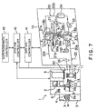
- Fig. 7 shows the structure of a modification of the processing system including a dry air supplying apparatus.
- a common heating means such as a heater 36a for heating dry air (i.e., recovery gas) to be supplied respectively to recovery zones U of two rotors 18a and 18b. That is, a second line 21b and a third line 21c having respective parts arranged adjacent to each other, and the common heater 36a is wound around the adjacent parts. Since the single heater 36a heats dry air to be supplied respectively to the recovery zones U of the two rotors 18a and 18b, a simple and compact configuration of the apparatus and a reduced manufacturing cost of the apparatus can be achieved.
- dry air i.e., recovery gas
- Fig. 8 shows another modification in which an exhaust passage 21 is provided with a common heating means such as a heater 36a to heat dry air (i.e., recovery gas) to be supplied respectively to recovery zones U of two rotors 18a and 18b, which is similar to the modification of Fig. 7.
- a branch pipe 44 bypassing the latter-rotor 18b is branched from a second line 21b at a position downstream of the heater 36a, and is joined to a third line 21c.
- a simple and compact configuration of the apparatus and a reduced manufacturing cost of the apparatus can be achieved.
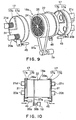
- Figs. 9 and 10 show a modification of the dry air supplying apparatus.
- a rotation shaft of a rotor 18a is omitted.
- the rotor 18a may be configured without including a rotation shaft.
- an outer circumference of the rotor 18a is supported such that the rotor 18a can rotate.
- the rotor 18a intermittently rotates.
- the partitioning members 17 leave the end faces of the rotor 18a when the rotor 18a is rotating (see left part of Fig. 10), and contact the end faces of the rotor 18a when the rotor 18a halts rotation (see right part of Fig. 10).
- the partitioning member 17 having a cover member 31 is provided with means, such as an air cylinder 45, for moving the partitioning member 17 toward or away from the end face of the rotor 18a.
- a sensor 46 is provided for detecting a rotation angle of the rotor 18a.
- a motor 19 is intermittently driven based on detection signals by the sensor 46, such that the rotor 18a can intermittently rotate, like a revolver, at every predetermined rotation angle.
- the rotor 18a intermittently rotates, and the partitioning members 17 are configured to leave the end faces of the rotor 18a when the rotor 18a is rotating, and contact the end faces of the rotor 18a when the rotor 18a halts rotation. Therefore, the rotor 18a does not slide on the partitioning member 17, thereby to prevent generation of particles from contact points between the rotor 18a and the portioning members 17.
- the present invention is not limited thereto, and various modifications are possible without departing from the gist of the present invention.
- the exhaust passage 21 shown in Fig. 1 is provided with the two heaters 36a and 36b, the heater 36b may be omitted so that the exhaust passage 21 is provided with only one heater 36a.
- a plurality of processing systems 1 may share the dry air supplying apparatus 15. In other words, dry air may be supplied by the dry air supplying apparatus 15 to a transfer space 10 of another processing system 1. In this way, the system configuration becomes more simplified and the system manufacturing cost can be further reduced.
Landscapes
- Chemical & Material Sciences (AREA)
- Engineering & Computer Science (AREA)
- Analytical Chemistry (AREA)
- General Chemical & Material Sciences (AREA)
- Oil, Petroleum & Natural Gas (AREA)
- Chemical Kinetics & Catalysis (AREA)
- Combustion & Propulsion (AREA)
- Mechanical Engineering (AREA)
- General Engineering & Computer Science (AREA)
- Separation Of Gases By Adsorption (AREA)
- Drying Of Gases (AREA)
- Treating Waste Gases (AREA)
Applications Claiming Priority (3)
| Application Number | Priority Date | Filing Date | Title |
|---|---|---|---|
| JP2002274214 | 2002-09-20 | ||
| JP2002274214 | 2002-09-20 | ||
| PCT/JP2003/012004 WO2004026442A1 (ja) | 2002-09-20 | 2003-09-19 | 乾燥空気供給装置及び処理装置 |
Publications (2)
| Publication Number | Publication Date |
|---|---|
| EP1552876A1 true EP1552876A1 (de) | 2005-07-13 |
| EP1552876A4 EP1552876A4 (de) | 2006-03-22 |
Family
ID=32024994
Family Applications (1)
| Application Number | Title | Priority Date | Filing Date |
|---|---|---|---|
| EP03797701A Withdrawn EP1552876A4 (de) | 2002-09-20 | 2003-09-19 | Trockenluftzufuhrvorrichtung und -behandlungsvorrichtung |
Country Status (6)
| Country | Link |
|---|---|
| US (1) | US7207123B2 (de) |
| EP (1) | EP1552876A4 (de) |
| KR (1) | KR20050057144A (de) |
| CN (1) | CN100384514C (de) |
| TW (1) | TWI264042B (de) |
| WO (1) | WO2004026442A1 (de) |
Families Citing this family (34)
| Publication number | Priority date | Publication date | Assignee | Title |
|---|---|---|---|---|
| JP2006068582A (ja) * | 2004-08-31 | 2006-03-16 | Seibu Giken Co Ltd | 回転式ガス吸着濃縮装置 |
| US7509588B2 (en) | 2005-12-30 | 2009-03-24 | Apple Inc. | Portable electronic device with interface reconfiguration mode |
| US7877895B2 (en) | 2006-06-26 | 2011-02-01 | Tokyo Electron Limited | Substrate processing apparatus |
| US10313505B2 (en) | 2006-09-06 | 2019-06-04 | Apple Inc. | Portable multifunction device, method, and graphical user interface for configuring and displaying widgets |
| US8619038B2 (en) | 2007-09-04 | 2013-12-31 | Apple Inc. | Editing interface |
| US7753995B2 (en) * | 2007-12-11 | 2010-07-13 | Seibu Giken Co., Ltd. | Gas concentrator |
| US8267081B2 (en) | 2009-02-20 | 2012-09-18 | Baxter International Inc. | Inhaled anesthetic agent therapy and delivery system |
| AT508754B1 (de) * | 2010-03-03 | 2011-04-15 | Wittmann Kunststoffgeraete | Einrichtung zum trocknen von schüttgut |
| JP5566732B2 (ja) * | 2010-03-10 | 2014-08-06 | 富士フイルム株式会社 | シーズニング装置 |
| DE102010011640B4 (de) * | 2010-03-16 | 2020-03-12 | Khs Gmbh | Schrumpftunnel zum Aufbringen von Schrumpffolien, Verfahren zum Betrieb oder Steuern eines Schrumpftunnels sowie Produktionsanlage mit einem Schrumpftunnel |
| US10788976B2 (en) * | 2010-04-07 | 2020-09-29 | Apple Inc. | Device, method, and graphical user interface for managing folders with multiple pages |
| US9170708B2 (en) | 2010-04-07 | 2015-10-27 | Apple Inc. | Device, method, and graphical user interface for managing folders |
| US9303884B2 (en) | 2010-06-22 | 2016-04-05 | Bry Air [Asia] Pvt. Ltd. | System and method for improving the performance of desiccant dehumidification equipment for low-humidity applications |
| KR20130032647A (ko) * | 2011-09-23 | 2013-04-02 | 삼성전자주식회사 | 웨이퍼 테스트 장치 |
| JP5452565B2 (ja) * | 2011-10-27 | 2014-03-26 | 三菱電機株式会社 | 除湿装置 |
| JP5453490B2 (ja) | 2011-12-21 | 2014-03-26 | 財團法人工業技術研究院 | 除湿と離脱装置及びシステム |
| SE537905C2 (sv) * | 2012-06-29 | 2015-11-17 | Ctt Systems Ab | Sorptionstorksystem och förfarande för avfuktning av en fuktig gasström |
| US10232306B2 (en) | 2012-06-29 | 2019-03-19 | Ctt Systems Ab | Sorption drying system |
| KR102132778B1 (ko) * | 2013-10-25 | 2020-07-13 | 삼성디스플레이 주식회사 | 액정 표시 장치 |
| EP3063608B1 (de) | 2013-10-30 | 2020-02-12 | Apple Inc. | Anzeige von relevanten benutzerschnittstellenobjekten |
| EP3086068A1 (de) * | 2015-04-20 | 2016-10-26 | Rhino Research Europe B.V. | Lufttrocknungssystem mittels absorbierenden zeolith |
| JP6367763B2 (ja) * | 2015-06-22 | 2018-08-01 | 株式会社荏原製作所 | ウェーハ乾燥装置およびウェーハ乾燥方法 |
| CN107362652A (zh) * | 2016-05-11 | 2017-11-21 | 中微惠创科技(上海)有限公司 | 可在线测量voc浓度的voc吸附设备及其方法 |
| US12175065B2 (en) | 2016-06-10 | 2024-12-24 | Apple Inc. | Context-specific user interfaces for relocating one or more complications in a watch or clock interface |
| DK201670595A1 (en) | 2016-06-11 | 2018-01-22 | Apple Inc | Configuring context-specific user interfaces |
| US11816325B2 (en) | 2016-06-12 | 2023-11-14 | Apple Inc. | Application shortcuts for carplay |
| WO2018200727A1 (en) * | 2017-04-25 | 2018-11-01 | Oceaneering International, Inc. | Continuously regenerable media purifier |
| CN110465159B (zh) * | 2019-07-25 | 2024-10-01 | 江苏苏净集团有限公司 | 一种处理废气用吸附转轮装置 |
| JP7041373B2 (ja) * | 2020-08-07 | 2022-03-24 | ダイキン工業株式会社 | 空調回転体及び空気処理装置 |
| JP2025518008A (ja) | 2022-05-27 | 2025-06-12 | インテグリス・インコーポレーテッド | フィルタモジュール |
| CN115400543B (zh) * | 2022-09-29 | 2023-06-09 | 广州福麟环保科技有限公司 | 一种VOCs废气处理装置 |
| US20240216852A1 (en) * | 2022-12-28 | 2024-07-04 | Munters Corporation | Sealing device for a gas sorption rotor of an air treatment system and a gas sorption rotor arrangement for an air treatment system |
| KR102600758B1 (ko) * | 2023-07-03 | 2023-11-10 | (주)오디씨티 | Cda용 정제시스템 |
| CN119607579B (zh) * | 2025-02-13 | 2025-05-16 | 坛墨质检科技股份有限公司 | 一种保证有机溶液稳定性的浓缩装置 |
Family Cites Families (15)
| Publication number | Priority date | Publication date | Assignee | Title |
|---|---|---|---|---|
| US3470708A (en) * | 1967-10-12 | 1969-10-07 | Inst Gas Technology | Solid-adsorbent air-conditioning device |
| US3889742A (en) * | 1973-11-13 | 1975-06-17 | Gas Dev Corp | Air conditioning apparatus and method |
| GB1533718A (en) | 1976-08-09 | 1978-11-29 | Nippon Steel Corp | Assembly for dehydrating air to be supplied to blast furnace |
| JPS6171821A (ja) | 1984-07-30 | 1986-04-12 | Daikin Ind Ltd | 乾式除湿装置 |
| JPH0694185B2 (ja) | 1990-02-27 | 1994-11-24 | ダイキン工業株式会社 | フツ素ゴムスポンジ積層体、およびそれを用いたハニカムロータ装置 |
| JP2971202B2 (ja) | 1991-08-05 | 1999-11-02 | 三菱重工業株式会社 | ガス回収装置 |
| US5248325A (en) * | 1991-05-09 | 1993-09-28 | Mitsubishi Jukogyo Kabushiki Kaisha | Gas separating system and gas recovery system |
| JP3120395B2 (ja) | 1993-03-10 | 2000-12-25 | 東京エレクトロン株式会社 | 処理装置 |
| JPH0947627A (ja) | 1995-08-09 | 1997-02-18 | Babcock Hitachi Kk | 排ガス浄化装置 |
| US6016710A (en) * | 1998-02-11 | 2000-01-25 | Semco Incorporated | Method and apparatus for measuring the quantity of outdoor air processed by an air preconditioning module |
| JP2000296309A (ja) | 1999-04-12 | 2000-10-24 | Daikin Ind Ltd | 半導体製造システム |
| JP4664459B2 (ja) * | 1999-07-28 | 2011-04-06 | 高砂熱学工業株式会社 | クリーンルームシステム |
| JP3570621B2 (ja) | 2000-03-30 | 2004-09-29 | ニチアス株式会社 | 回転型ガス吸着機におけるシール装置 |
| JP2002013759A (ja) | 2000-06-28 | 2002-01-18 | Earth Clean Tohoku:Kk | デシカント空調方法 |
| JP2002186824A (ja) | 2000-12-20 | 2002-07-02 | Fujitsu General Ltd | 除湿機 |
-
2003
- 2003-09-19 TW TW092126021A patent/TWI264042B/zh not_active IP Right Cessation
- 2003-09-19 EP EP03797701A patent/EP1552876A4/de not_active Withdrawn
- 2003-09-19 CN CNB038222787A patent/CN100384514C/zh not_active Expired - Fee Related
- 2003-09-19 WO PCT/JP2003/012004 patent/WO2004026442A1/ja not_active Ceased
- 2003-09-19 KR KR1020057003700A patent/KR20050057144A/ko not_active Ceased
- 2003-09-19 US US10/528,230 patent/US7207123B2/en not_active Expired - Fee Related
Also Published As
| Publication number | Publication date |
|---|---|
| TWI264042B (en) | 2006-10-11 |
| KR20050057144A (ko) | 2005-06-16 |
| CN100384514C (zh) | 2008-04-30 |
| CN1681576A (zh) | 2005-10-12 |
| EP1552876A4 (de) | 2006-03-22 |
| TW200416782A (en) | 2004-09-01 |
| US20050246918A1 (en) | 2005-11-10 |
| WO2004026442A1 (ja) | 2004-04-01 |
| US7207123B2 (en) | 2007-04-24 |
Similar Documents
| Publication | Publication Date | Title |
|---|---|---|
| US7207123B2 (en) | Dry air-supplying apparatus and treating apparatus | |
| JP3896343B2 (ja) | 乾燥空気供給装置 | |
| US4946479A (en) | Apparatus for solvent recovery | |
| JPH0775714A (ja) | 有機溶剤蒸気吸着装置 | |
| KR100956356B1 (ko) | 에너지축열회수형 유해물질 처리설비 | |
| JP2004160444A (ja) | 乾燥空気供給装置及び処理装置 | |
| US4895580A (en) | Gas treating apparatus | |
| JP4167114B2 (ja) | 処理装置及びその運転方法 | |
| JPH05200233A (ja) | 乾式除湿装置 | |
| KR102831782B1 (ko) | Voc 필터 및 데시칸트를 이용한 efem 공기 조화 시스템 | |
| JP2020089858A (ja) | 空気浄化装置 | |
| JP6420115B2 (ja) | 気体処理装置及び気体処理装置の機能再生方法 | |
| JP3896344B2 (ja) | 乾燥空気供給装置の運転方法 | |
| JP2681403B2 (ja) | ガス収着方法およびガス収着装置 | |
| JP2002331221A (ja) | 除湿方法及びその装置 | |
| JP4250380B2 (ja) | ガス濃縮装置及びガス濃縮方法 | |
| JPH08112512A (ja) | 気体処理装置 | |
| JP2002143632A (ja) | エチレン除去装置及びこのエチレン除去装置を備えた冷蔵庫 | |
| JP2002273158A (ja) | ガス吸着濃縮装置 | |
| JP2005089029A (ja) | 空気輸送装置 | |
| CN117883956B (zh) | 一种气体干燥装置及方法 | |
| JP2002159821A (ja) | 有機ガス濃縮装置 | |
| KR102741183B1 (ko) | 제습기능을 갖는 반도체설비 | |
| JP6463062B2 (ja) | 気体制御装置、ロータを用いた気体制御装置のゾーン間リークの低減方法、及び気体制御システム | |
| JPH0722378A (ja) | 基板回転乾燥装置の排気装置 |
Legal Events
| Date | Code | Title | Description |
|---|---|---|---|
| PUAI | Public reference made under article 153(3) epc to a published international application that has entered the european phase |
Free format text: ORIGINAL CODE: 0009012 |
|
| 17P | Request for examination filed |
Effective date: 20050420 |
|
| AK | Designated contracting states |
Kind code of ref document: A1 Designated state(s): AT BE BG CH CY CZ DE DK EE ES FI FR GB GR HU IE IT LI LU MC NL PT RO SE SI SK TR |
|
| RBV | Designated contracting states (corrected) |
Designated state(s): DE FR GB IT NL |
|
| A4 | Supplementary search report drawn up and despatched |
Effective date: 20060206 |
|
| RIC1 | Information provided on ipc code assigned before grant |
Ipc: F24F 3/14 20060101ALI20060131BHEP Ipc: B01D 53/06 20060101ALI20060131BHEP Ipc: B01D 53/26 20060101AFI20040406BHEP |
|
| 17Q | First examination report despatched |
Effective date: 20070820 |
|
| STAA | Information on the status of an ep patent application or granted ep patent |
Free format text: STATUS: THE APPLICATION IS DEEMED TO BE WITHDRAWN |
|
| 18D | Application deemed to be withdrawn |
Effective date: 20100401 |