EP1552892B1 - Vorrichtung zum Richten von Metallbändern - Google Patents
Vorrichtung zum Richten von Metallbändern Download PDFInfo
- Publication number
- EP1552892B1 EP1552892B1 EP05300003A EP05300003A EP1552892B1 EP 1552892 B1 EP1552892 B1 EP 1552892B1 EP 05300003 A EP05300003 A EP 05300003A EP 05300003 A EP05300003 A EP 05300003A EP 1552892 B1 EP1552892 B1 EP 1552892B1
- Authority
- EP
- European Patent Office
- Prior art keywords
- active roll
- roll
- machine
- fact
- straightening
- Prior art date
- Legal status (The legal status is an assumption and is not a legal conclusion. Google has not performed a legal analysis and makes no representation as to the accuracy of the status listed.)
- Expired - Lifetime
Links
- 239000002184 metal Substances 0.000 title claims description 25
- 238000000034 method Methods 0.000 claims abstract description 7
- 230000033001 locomotion Effects 0.000 claims abstract description 5
- 230000000284 resting effect Effects 0.000 claims description 10
- 238000005096 rolling process Methods 0.000 claims description 4
- 238000009987 spinning Methods 0.000 claims 14
- 238000003780 insertion Methods 0.000 claims 2
- 230000037431 insertion Effects 0.000 claims 2
- 230000001360 synchronised effect Effects 0.000 abstract 1
- 238000005452 bending Methods 0.000 description 5
- 230000000694 effects Effects 0.000 description 5
- 238000003032 molecular docking Methods 0.000 description 5
- 238000006073 displacement reaction Methods 0.000 description 4
- 238000009434 installation Methods 0.000 description 4
- 238000012423 maintenance Methods 0.000 description 4
- 229910000831 Steel Inorganic materials 0.000 description 3
- 230000007547 defect Effects 0.000 description 3
- 230000002093 peripheral effect Effects 0.000 description 3
- 239000010959 steel Substances 0.000 description 3
- 238000011144 upstream manufacturing Methods 0.000 description 3
- 238000000137 annealing Methods 0.000 description 2
- 230000005540 biological transmission Effects 0.000 description 2
- 230000006835 compression Effects 0.000 description 2
- 238000007906 compression Methods 0.000 description 2
- 238000012937 correction Methods 0.000 description 2
- 230000006866 deterioration Effects 0.000 description 2
- 238000005246 galvanizing Methods 0.000 description 2
- 210000000056 organ Anatomy 0.000 description 2
- 238000012545 processing Methods 0.000 description 2
- 238000003466 welding Methods 0.000 description 2
- 239000000919 ceramic Substances 0.000 description 1
- 229910010293 ceramic material Inorganic materials 0.000 description 1
- 238000013461 design Methods 0.000 description 1
- 238000004519 manufacturing process Methods 0.000 description 1
- 238000005272 metallurgy Methods 0.000 description 1
- 230000000135 prohibitive effect Effects 0.000 description 1
- 238000006748 scratching Methods 0.000 description 1
- 230000002393 scratching effect Effects 0.000 description 1
- 238000010008 shearing Methods 0.000 description 1
- 238000003892 spreading Methods 0.000 description 1
- 229910001220 stainless steel Inorganic materials 0.000 description 1
Images


Classifications
-
- B—PERFORMING OPERATIONS; TRANSPORTING
- B21—MECHANICAL METAL-WORKING WITHOUT ESSENTIALLY REMOVING MATERIAL; PUNCHING METAL
- B21D—WORKING OR PROCESSING OF SHEET METAL OR METAL TUBES, RODS OR PROFILES WITHOUT ESSENTIALLY REMOVING MATERIAL; PUNCHING METAL
- B21D1/00—Straightening, restoring form or removing local distortions of sheet metal or specific articles made therefrom; Stretching sheet metal combined with rolling
- B21D1/05—Stretching combined with rolling
-
- B—PERFORMING OPERATIONS; TRANSPORTING
- B21—MECHANICAL METAL-WORKING WITHOUT ESSENTIALLY REMOVING MATERIAL; PUNCHING METAL
- B21B—ROLLING OF METAL
- B21B13/00—Metal-rolling stands, i.e. an assembly composed of a stand frame, rolls, and accessories
- B21B13/02—Metal-rolling stands, i.e. an assembly composed of a stand frame, rolls, and accessories with axes of rolls arranged horizontally
Definitions
- the subject of the invention is a leveling machine that can be used, in particular, in a tensile planing installation of a metal strip and also covers the process used.
- JP-A-63-149017 discloses a machine and a planing method described in the preamble of claims 1 and 22.
- planing machines are usually used to eliminate as much as possible the unevennesses appearing as a result of rolling.
- a leveling machine comprises, in a general manner, a certain number of rollers rotatably mounted about axes orthogonal to a running direction of the band to be hovered and offset longitudinally and vertically, so as to define a corrugated path of the strip which, in addition, is under tension and thus undergoes traction-bending effects in opposite directions to homogenize the stresses.
- such a machine comprises, inside a frame not shown on the figure 1 at least two longitudinally offset planing crews, respectively an upper crew E 'and a lower crew E, placed respectively above and below the band M and mechanical or hydraulic means for controlling the vertical displacements of each crew plane, transversely to the strip travel plane, between a planing position and a rest position spaced from the strip.
- such a machine may comprise, for example, two bending units F1, F2, each comprising an upper planing unit E 'and a lower unit E, a bending unit T carrying a so-called "tile corrector” roller vertically adjustable by a mechanical system and, often, another bending unit carrying a "hanger” or decambering correction roll.
- Each leveling unit comprises a transverse frame, movable vertically in the frame and carrying a leveling cylinder, called active cylinder, rotatably mounted about an axis transverse to the scroll direction.
- active cylinder For leveling, the active cylinder is of small diameter, and must therefore be supported on support members consisting, in most cases, of two intermediate rollers themselves resting on three rows of rollers.
- the active planishing cylinders must have a relatively small diameter and therefore rotate at a very high speed, resulting in relatively rapid wear of their outer faces.
- the active cylinders and possibly the intermediate rollers must therefore be replaced periodically.
- a disassembly device is usually used which makes it possible to remove the assembly of the planing unit requiring maintenance and to spread it laterally on one side of the machine, the metal strip being able to remain in the machine, ie 'stop, either while scrolling.
- a simple change of the active cylinders or any other short-term maintenance it is preferable to stop only the planeuse to open it and replace the cylinders without stopping the running of the band in the processing section.
- planing was done in separate machines, the band running from a coil placed upstream to be rewound downstream.
- planing machines it is now necessary to install planing machines in continuous lines used, in particular, for annealing or hot-dip galvanizing the strip.
- the coils are welded end to end at the line entrance, the strip being cut into coils at the outlet.
- Tape accumulators are therefore placed, respectively, upstream and downstream to ensure a constant speed of travel of the strip in a central processing section during the stop required for the inlet for welding or the exit for shearing. .
- the planers are normally installed in this central section at a substantially constant speed in order to obtain the desired regularity of the quality parameters of the product.
- the welding between two successive coils is usually an extra thickness that may deteriorate the planing rolls.
- it is preferable to open the planer by spreading the planing rolls at the time of the passage of the weld and then bringing them into contact with the strip.
- the set of active cylinders, intermediate rollers and support rollers is then again dragged by friction during the docking of the equipment on the belt and this inevitably results in slippage due to inertia. rotation of the various cylinders and rollers for a few seconds which may, however, correspond to several tens of meters of tape, given the speed of scrolling.
- the document JP-A-63-149017 provides for rotating the central row of support rollers, the latter being mounted on a splined shaft connected to a motor by a clutch. The rotational movement is then transmitted by friction to the intermediate rollers and then to the active roll, the rotational speed of the driven rollers being adjusted so as to give the active roll an angular velocity corresponding to the running speed of the roll, which allows avoid skating at the time of docking.
- the torque is transmitted to the active cylinder only by friction and this effect depends on the application pressure of the rotating members on each other.
- this application pressure is simply the weight of the active cylinder and the intermediate rollers, as long as the active cylinder is not applied to the belt.
- the active cylinder must be carried at its ends by two bearings suspended from the chassis of the crew by springs which pull up the active cylinder in order to apply it to the intermediate rollers. and the support rollers.
- the springs are connected to the bearings by removable hooks.
- the angular velocity of the support rollers on which the torque is applied must be adjusted according to the ratio of diameters of said rollers, intermediate rollers and the active cylinder so that the angular velocity of the latter corresponds exactly to the speed of the tape.
- the diameters of these different members may vary slightly due to wear and must be taken into account for the adjustment of angular velocities.
- this wear is not evenly distributed over the length of the rolls and there may therefore be a slight difference in diameter and, consequently, in peripheral speed between the successive rollers of the row driven in rotation. This difference results in increased wear of parts of the intermediate rollers and active rolls which can result in defects on the web. The objective sought may therefore not be achieved.
- the invention overcomes these various drawbacks with a new arrangement allowing, by very simple means, to surely drive the active cylinders at an angular speed corresponding to the speed of travel of the product, while maintaining a possibility easy and quick disassembly and reassembly of the active cylinders and, if necessary, intermediate rollers.
- the invention therefore applies, in a general manner, to a leveling machine comprising at least two leveling equipments placed on either side of the strip and each comprising an active cylinder and a set of support members. mounted rotatably about their axes on a transverse frame, the assembly being movable parallel to itself between a rest position for which the active cylinder is spaced from the strip and a leveling position for which the active cylinder is applied to the band bearing on the support side, on the opposite side, each active cylinder can be rotated, before its application on the band, at an angular speed corresponding substantially to the speed of travel of the band.
- the rotational drive of each active cylinder is determined by direct application of a rotational torque on one end of said cylinder, at an angular speed controlled by the running speed of the strip.
- each active cylinder is carried at each of its ends by a centering pin rotatably mounted about the axis of the cylinder, on a support member slidably mounted on the transverse frame of the crew parallel to a plane.
- radial axis passing through the axis of said active cylinder, the positions relative to said frame of the two support pieces being adjustable by radial sliding for the displacement of the active cylinder, parallel to its axis, between a application position on its support members and a spaced position, and one of the centering pins of each active cylinder is connected to a means for direct application of a rotational torque on said pin.
- each support part of an active cylinder comprises a first portion in the form of a cylindrical housing, in which is mounted a rotatable support bearing of the active cylinder, centered on a radial plane passing through the axis of said cylinder. , and a second portion forming an arm slidably mounted on a slide formed on a guide foot fixed to the transverse frame of the leveling crew.
- each piece of sliding support is associated with a return means bearing in one direction on the support piece and in the other on the transverse frame, for the application of the active cylinder on its support members.
- each support member comprises a support means on the frame, advantageously constituted by a cam mounted rotatably between at least two positions, respectively a position spaced from the frame, allowing the application of the active cylinder on its support members , thanks to the biasing means bearing on said support member and a bearing position on the frame to push the support member against the action of the biasing means.
- each support member comprises a bearing portion provided with at least one through hole of at least one guide rod fixed by a first end to the transverse frame and extending, on the other side of the support portion of the support piece, to a second end on which is formed a support flange of a resilient means compressed between said flange and the support portion of the support piece .
- each support part of an active cylinder carries a centering bearing with a rotating internal cage in which is threaded a support pin fixed on the end of the active cylinder, in the axis thereof.
- one of the two journals being extended outwardly by a drive end connected to a means for controlling the rotation of the journal with the active cylinder, about its axis.
- each of the two support journals of the active cylinder forms a shaft end provided, on the side of the active cylinder, with a detachable connecting means with the active cylinder, said shaft end being axially displaceable between a constricted position of connection with the cylinder, for the rotary support of the latter and a spaced apart position, disengaged from the end of the cylinder, for disassembly of the latter, the connecting means being able to consist of two parts of conjugate forms formed respectively on the trunnion; and the end of the cylinder and engaging one another by axial displacement of the journal from a spaced apart position to a constricted position.
- At least the support member of the driving pin of each active cylinder is slidably mounted parallel to a radial plane passing through the axis of said cylinder, on a guide foot integral with a sliding mounted base on the transverse frame, parallel to the axis of the active cylinder, between a constricted position of the two support pieces for engaging the ends of the active cylinder on the centering bearings and a spaced apart position of the ends of the active cylinder, for the disassembly of the latter, the transverse frame being provided with means for fixing the base of the guide foot of each support piece in the constricted position of engagement of the ends of the active cylinder on the centering bearings.
- the active cylinder in the rest position of the planing equipment, can be separated from its support rollers by the two cams, in order to be disassembled and, after reassembly between the two journals, it is pushed back by the two support pieces in the opposite direction so as to bear in advance on its support members. In this position, it is rotated at a peripheral speed corresponding to the running speed of the strip, also driving the support members, so that the contact with the strip, in the planing position, can occur without risk of slippage and, therefore, deterioration of the surface quality of the product.
- the rotational torque is applied directly to the active cylinder, the angular speed of rotation thereof around its axis can be slaved to the running speed of the tape and this, not only in the position rest of the planing crew but also, during the planing, in the working position of the crew.
- the figure 1 is a schematic view of the assembly of a leveling installation.
- the figure 2 is an overview, from the side, of a superior planing crew.
- the figure 3 is a detail view, in axial section, of one end of the upper planing crew.
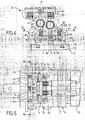
- the figure 4 is a side view of the two planing crews.
- the figure 5 is a horizontal sectional view along line VV of the figure 4 .
- the figure 1 schematically shows the conventional layout of a leveling installation comprising for example two flexion units F1-F2 and a tile correction device T, associated with deflection rollers D and adjustable in height, in order to define a corrugated path of the strip M that runs between the successive rollers in a longitudinal direction parallel to the plane of the figure 1 .
- the strip is put under tension by known means such as so-called "S-roll” tensioning rollers placed upstream and downstream.
- the figure 1 shows, for example, the downstream tensioner device S.
- Each bending unit comprises two planing crews, respectively lower E and upper E 'longitudinally offset and each having, usually, an active cylinder A associated with two intermediate rollers I which are supported on three rows of support rollers G when the cylinder active A is applied to the strip in the planing position shown on the figure 1 by vertical displacement of the frame C, for example, by means of jacks or screws not shown.
- the transverse frame of the upper crew E ' is rotatably mounted about a horizontal axis, according to a provision subject to the FR-A-2,659,254 from the same company, which makes it possible to turn up the entire crew to facilitate disassembly and replacement of cylinders and rollers.
- the active cylinder A and the intermediate rollers I bear on each other and on the rollers G only in the planing position and that is why they are carried with play by the transverse frame C and are only held laterally by axial stops.
- the active cylinder 2 is provided, at its opposite ends, with two journals 3, 3 'centered on the axis 20 of the cylinder and rotatably mounted, by means of bearings 30, 30', on two support pieces 4, 4 'in the way shown in more detail on the figures 3 , 4 and 5 .
- each support piece 4 forms a sort of chock centered on a radial plane P passing through the axis 20 of the active cylinder 2 and comprises an arm 41 mounted to slide radially on a guide foot 5 extending towards the strip from the frame 1, and a box-shaped portion 40 fixed to the end of the arm 41 opposite the frame, and in which is inserted the bearing 30 of the pin 3.
- each support piece 4 of one end of the active cylinder 2 is associated with return means 6 for applying the active cylinder 2 to its support members which consist, in the example shown, of two intermediate rollers 7, 7 ', held axially between the two guide feet 5, 5' and resting on three rows of support rollers 70 rotatably mounted on the transverse frame 1.
- each support piece 4, 4 ' is provided, on the side of the frame 1, with a sole 44 on which at least two springs 6 spaced apart symmetrically on either side of the radial plane P and bearing , in the opposite direction, on the chassis 1.
- each spring 6 is threaded onto a bushing 61 passing through an orifice of the soleplate 44 of the chock 4 and fixed on the chassis 1 by an axial screw 62, the bushing 61 comprising a compression flange 63 of the spring 6.
- Each chock 4, 4 ' is thus mounted to slide radially on at least two bushes 61 and pushed towards the frame 1 by the springs 6 compressed between the flanges 63 and the flange 44 which extends parallel to the base 51, at a low distance from it.
- the two chocks 4, 4 'supporting the ends of the active roller 2 are thus pushed towards the transverse frame 1 by applying the active cylinder on the intermediate rollers 7, 7' which bear on the rollers 70.
- the intermediate rollers 7 are not carried by bearings but simply held laterally between two axial abutments each consisting of a ceramic chip 71 mounted in a housing 72 fixed by a rear extension 73 on the guide foot 5.
- the guide foot 5 comprises two spaced apart amounts 52 carrying the slides 50, between which extends a crossbar 54 provided with two recesses 53 in which are threaded the extensions 73 of the two stops 71 of centering, respectively, of the two intermediate rollers 7, 7 '.
- Each housing 72 is held by a clamping screw engaging in a threaded bore of the extension 73 which is slidably mounted in the housing 53 parallel to the bisecting plane of the two rows of rollers 70 on which it is supported, with a clearance allowing slight adjustments of the intermediate roll.
- the active cylinder 2 when the active cylinder 2 is applied by the springs 6 to the support rollers 7, the latter can move slightly, parallel to themselves so as to be applied on the support rollers 70.
- the active cylinder 2 is subject to wear and must be replaced.
- the bases 51 of the two guide feet 5 carrying the two support pieces 4 are slidably mounted on the transverse frame 1, parallel to the axes of the cylinders.
- each base 51 is provided with a central groove which engages on a rectilinear boss 11 of the transverse frame 1.
- it is provided with two longitudinal housings 12 inside which are mounted sliding, respectively, two strips 13 connected to the base 51 by screws 14 which, after sliding, to block the base 51 in the chosen position.
- each pin 3 of the active cylinder consists of two parts engaging one in the other and secured by a screw 34, respectively a pivot 31 fixed to the end of the active cylinder 2, in the axis of this, and a shaft end 32 threaded into the bearing 30 and, therefore, axially secured to the support part 4 and the guide foot 5.
- the pivot 31 and the shaft end 32 are provided with conical conical portions respectively formed recessed and projecting, and engaging one into the other to ensure both the centering and the rotational drive of the active cylinder 2, one of the shaft ends 32, for example the one on the left on the figure 3 , being provided with a tip 33 on which is applied a rotational torque produced by a motor means not shown.
- each chock 4, 4 'of a trunnion 3, 3' of the active cylinder 2 is equipped with a cylinder spacing means constituted, in the embodiment shown in the drawings, of a cam 8 to eccentric profile rotatably mounted on the central rib 41 of the chock 4 about an axis 80.
- a rotation of the eccentric cam 8 about its axis 80 makes it possible to push the sole 44 of each support piece 4, 4 'by increasing the compression of the springs 6.
- the active cylinder 2 thus being slightly spaced from the intermediate rollers 7, 7 ', it is possible to spread laterally the two guide feet 5, 5' with the support pieces 4, 4 'to release the pivots 31 at both ends of the cylinder 2.
- the two guide feet 5 can be moved axially apart with the support pieces 4, 4 ' and the bearings 30, 30 'which drive the shaft ends 32, 32'.
- the transverse frame 1 is rotatably mounted about a horizontal axis 15, according to a provision which is the subject of the French patent FR 2,659,254 already cited. Indeed, before any disassembly operation, it is thus possible to return 180 ° the upper leveling unit E 'so that the active cylinder 2 is placed above its support members and is based on these last when one discards the two ends of the shaft 32, 32 'with the chocks 4, 4'.
- the chocks 4, 4' are tightened so that the conical portions of the pivot 31 and the shaft end 32 engage one into the other. other.
- the cylinder 2 can then be applied to the intermediate rollers 7, 7 'by rotating in the opposite direction the eccentric cams 8 which are provided with a flat face 81, in order to allow the springs 6 to push the sole 44 towards the base 51.
- the spacing (e) between the sole 44 and the base 51 is kept at a minimum value by adjustable stops 64 consisting of screws engaging in threaded bores of the sole 44.
- one of the two journals of each active cylinder 2, for example the left trunnion 3 on the figure 2 is extended by a drive end 33, for example fluted, which can be removably connected to a motor means such as geared motor, pulley and belt or other motion transmission member, according to the general arrangement selected for the machine .
- a motor means 9 indicated schematically on the Figures 1 and 2 , can be arranged on the fixed frame or on the frame of each planing equipment E, E 'and removably connected to the active cylinder 2, 2', by a telescopic double cardan extension 36 for transmitting the torque to following all the positions of the axis of the active cylinder, according to the diameters of all its support members.
- easy to design means to adjust the rotational speed of the active cylinders of the two planing crews, taking into account their diameters, so as to slave their peripheral speeds to the linear speed of the moving strip.
- This speed of movement can be measured at any moment by a sensor 92, for example from the speed of rotation of the rollers of one of the tensioning units S which, as currently, are placed on either side of the leveling machine in order to put the band in tension.
- the active cylinders 2 can then be started in rotation and they frictionally drive the intermediate rollers and the support rollers.
- the speed of synchronism with the band is reached, one can proceed to the closing of the machine by placing the two crews E, E 'in their planing positions, the docking of the active cylinders on the band being done thus without skating and without risk of marking the product.
- the latter can be driven permanently at an angular speed corresponding to the running speed of the strip, which makes it possible to absorb variations in the planing speed without risk of slipping, even for low friction bands.
- the springs 6 could be replaced by other means.
- the application forces of the active cylinder are not the same for the lower equipment E and for the upper equipment E 'whose weight must be compensated.
- the chocks of the upper active cylinder are advantageously associated with two pairs of springs symmetrical with respect to the radial plane P, on the one hand the springs 60 which exert only the application pressure necessary for the rotational drive of the cylinder and rollers intermediate, and secondly, two springs 65 which are tared so as to take up the weight of the active cylinder 2 with its two chocks 4, 4 ', its drive means 36 and, in a general manner, all the organs which are not worn directly by the chassis.
Landscapes
- Mechanical Engineering (AREA)
- Engineering & Computer Science (AREA)
- Metal Rolling (AREA)
- Soil Working Implements (AREA)
- Iron Core Of Rotating Electric Machines (AREA)
- Reduction Rolling/Reduction Stand/Operation Of Reduction Machine (AREA)
- Orthopedics, Nursing, And Contraception (AREA)
- Coating With Molten Metal (AREA)
- Manufacture Of Alloys Or Alloy Compounds (AREA)
- Casting Or Compression Moulding Of Plastics Or The Like (AREA)
- Replacement Of Web Rolls (AREA)
- Folding Of Thin Sheet-Like Materials, Special Discharging Devices, And Others (AREA)
- Straightening Metal Sheet-Like Bodies (AREA)
- Wire Processing (AREA)
Claims (24)
- Vorrichtung zum Richten von Metallbändern mit Mitteln zum Steuern des Ablaufens des Bandes unter Zug in Längsrichtung und entlang einer Ablaufebene, mit mindestens zwei Richteinheiten E, E', die beiderseits des Bandes M angeordnet sind und jeweils eine Richtwalze (A, 2) und eine Anordnung (1, 7) aus Stützelementen, die an einem Querrahmen (C, 1) um zueinander parallele und im rechten Winkel zur Bandlaufrichtung liegende Drehachsen herum drehend montiert sind, umfassen, und mit Mitteln zur Steuerung der Bewegung jeder Richteinheit (E, E') parallel zu sich selbst zwischen einer Ruheposition, in der die Richtwalze (A, 2) vom Band beabstandet ist, und einer Arbeitsposition, in der die Richtwalze an das Band angestellt ist und auf der gegenüberliegenden Seite auf ihren Stützelementen (1, 7) aufliegt, wobei jede Richtwalze (2) vor dem Anstellen an das Band (M) mit einer Winkelgeschwindigkeit, die in etwa der Bandablaufgeschwindigkeit entspricht, drehend angetrieben werden kann,
dadurch gekennzeichnet, dass jede Richtwalze (2, 2') an jedem ihrer Enden von einem Zentrierzapfen (3, 3') getragen wird, der um die Achse der Walze drehend an einem Tragteil (4, 4') montiert ist, das am Querrahmen (1) der Einheit (E, E') parallel zu einer radialen Ebene (P), die durch die Achse der Richtwalze (2) verläuft, verschiebbar montiert ist, dass die Positionen der beiden Tragteile (4, 4') in Bezug auf den Rahmen zum Bewegen der Richtwalze (2) durch radiales Verschieben parallel zur Achse der Walze zwischen einer Anstellposition an den Stützelementen (7, 7') und einer beabstandeten Position eingestellt werden kann und dass jede Richtwalze (2, 2') durch direktes Anwenden eines Drehmoments an einen ihrer Zentrierzapfen (3) um ihre Achse drehend angetrieben werden kann. - Richtvorrichtung nach Anspruch 1, dadurch gekennzeichnet, dass jedes Tragteil (4, 4') einer Richtwalze (2) ein gehäuseförmiges Teil (40) umfasst, in dem ein Lager (30) zur drehenden Abstützung des entsprechenden Zapfens (3, 3') der Richtwalze (2) montiert ist, das auf eine radiale, durch die Achse (20) der Walze (2) verlaufenden Ebene (P) zentriert ist, und einen Arm (41), der verschiebbar auf einer Gleitschiene (50) montiert ist, die auf einem am Querrahmen (1) der Richtvorrichtung befestigten Führungsfuß (5) angeordnet ist.
- Richtvorrichtung nach einem der Ansprüche 1 und 2, dadurch gekennzeichnet, dass jedes verschiebbare Tragteil (4, 4') mit einem Rückstellmittel (6) zum Anstellen der Richtwalze (2) an ihre Stützelemente (7,7') kombiniert ist, das in einer Richtung am Tragteil (4) anliegt und in entgegengesetzter Richtung am Querrahmen (1).
- Richtvorrichtung nach Anspruch 3, dadurch gekennzeichnet, dass jedes Tragteil (4, 4') ein Mittel (8) zur Auflage am Rahmen (1) umfasst, um die Richtwalze (2) gegen die Kraft des Rückstellmittels (6) in eine Aus- und Wiedereinbauposition zu drücken, in der die Richtwalze (2) von ihren Stützelementen (7, 7') beabstandet ist oder frei auf diesen ruht.
- Richtvorrichtung nach Anspruch 4, dadurch gekennzeichnet, dass das Auflagemittel (8) ein Nocken ist, der um eine Achse (80) drehend montiert ist und eine Fläche umfasst, die sich durch Drehen um die Achse (80) am Rahmen (1) abstützt, um das Tragteil (4, 4') gegen die Kraft des Rückstellmittels (6) zu drücken, und eine ebene Fläche (81), die durch Drehen des Nockens (8) in eine vom Rahmen (1) beabstandete Position gelangt, um das Anstellen der Richtwalze (2) an ihre Stützelemente (7) durch die Rückstellmittel (6) zu ermöglichen.
- Richtvorrichtung nach einem der Ansprüche 1 bis 5, dadurch gekennzeichnet, dass jedes Tragteil (4) ein Auflageteil (44) umfasst, das mit mindestens einem Loch zum Durchführen von mindestens einer Führungsstange (61) versehen ist, die über ein erstes Ende am Querrahmen (1) befestigt ist und sich auf der anderen Seite des Auflageteils (44) des Tragteils bis zu einem zweiten Ende erstreckt, an dem ein Auflageflansch (63) eines federnden Rückstellmittels (6), das zwischen diesem Flansch (63) und dem Auflageteil (44) des Tragteils (4) zusammengedrückt wird, angeordnet ist.
- Richtvorrichtung nach Anspruch 6, dadurch gekennzeichnet, dass jedes Tragteil (4) radial verschiebbar auf mindestens zwei Führungsstangen (61) montiert ist, die jeweils durch ein Loch des Auflageteils (44) geführt sind und jeweils mit einer Feder (6) kombiniert sind, die auf dieser Stange (61) sitzt und zwischen dem Auflageteil (44) und einem am Ende der Führungsstange (61) angeordneten Flansch (63) zusammengedrückt wird.
- Richtvorrichtung nach Anspruch 7, dadurch gekennzeichnet, dass jede Führungsstange aus einer Hülse (61) besteht, die auf einer Schraube (62) sitzt, die am Auflageteil (44) des Tragteils (4) befestigt ist und sich an einem Flansch (63) abstützt, der an dem dem Auflageteil (44) gegenüberliegenden Ende der Hülse (61) angeordnet ist, wobei eine Feder (6) auf der Hülse (61) sitzt und durch Anziehen der Schraube (62) zwischen dem Flansch (63) und dem Auflageteil (44) zusammengedrückt wird.
- Richtvorrichtung nach Anspruch 8, dadurch gekennzeichnet, dass die beiden Tragteile (4, 4') der Enden jeder Richtwalze (2) jeweils mit Rückstellmitteln (6) kombiniert sind, die so vorgespannt sind, dass sie die Richtwalze (2) unter einem Druck, der gerade ausreicht, um den kraftschlüssigen Antrieb der Stützelemente (7, 70) durch die Richtwalze (2) zu gewährleisten, an ihre Stützelemente (7, 70) anstellen.
- Richtvorrichtung nach Anspruch 9, dadurch gekennzeichnet, dass die beiden Tragteile (4, 4') der Richtwalze (2) der oberen Richteinheit (E') jeweils mit einem ersten Rückstellmittel (60) kombiniert sind, das so vorgespannt ist, dass es die Richtwalze (2) an ihre Stützelemente (7, 70) anstellt, und darüber hinaus mit einem zweiten Rückstellmittel (65), das so vorgespannt ist, dass es das Gewicht der Richtwalze, ihrer Tragteile (4, 4') und der Elemente (36), die nicht direkt vom Tragrahmen (1) getragen werden, ausgleicht.
- Richtvorrichtung nach einem der vorangehenden Ansprüche, dadurch gekennzeichnet, dass jedes Tragteil (4) ein Lager (30) zur drehenden Zentrierung eines Endes (3) einer Richtwalze (2) trägt, das mindestens ein Wälzelement mit einem am Tragteil (4) befestigten Außenkäfig (30a) umfasst und einen drehenden Innenkäfig (30b), in den ein Zentrierzapfen (3) eingeführt ist, der am entsprechenden Ende der Richtwalze (2) befestigt ist und auf deren Drehachse (20) zentriert ist.
- Richtvorrichtung nach einem der vorangehenden Ansprüche, dadurch gekennzeichnet, dass einer (3) der beiden an den Enden der Richtwalze (2) befestigten Zapfen nach außen durch ein Antriebsansatzstück (33) verlängert wird, das mit einem Mittel (36) zum Anwenden eines Drehmoments am Zapfen (3) zum Antreiben der Walze (2) um ihre Achse (20) mit einer gewünschten Winkelgeschwindigkeit verbunden ist.
- Richtvorrichtung nach einem der vorangehenden Ansprüche, dadurch gekennzeichnet, dass mindestens das Tragteil (4) des Antriebszapfens (3) verschiebbar auf einem Führungsfuß (5) montiert ist, der wiederum am Querrahmen (1) parallel zur Achse der Richtwalze (2) verschiebbar montiert ist, zwischen einer angezogenen Position der beiden Tragteile (4, 4') zum Einführen jedes Endes (31, 31') der Richtwalze (2) in das entsprechende Tragteil (4, 4') und einer beabstandeten Position zum Ausführen der Enden (31, 31') der Richtwalze (2) zu deren Ausbau.
- Richtvorrichtung nach einem der vorangehenden Ansprüche, dadurch gekennzeichnet, dass mindestens der Antriebszapfen (3), an dem das Drehmoment angreift, abnehmbar mit dem entsprechenden Ende (31) der Richtwalze (2) verbunden ist.
- Richtvorrichtung nach Anspruch 14, dadurch gekennzeichnet, dass mindestens der Antriebszapfen (3) einen Wellenstumpf (32) umfasst, der drehend am Tragteil (4) montiert ist und mit einem abnehmbaren Mittel zur Verbindung mit dem Ende (31) der Richtwalze versehen ist, wobei dieser Wellenstumpf (32) mit dem Tragteil (4) zwischen einer angezogenen Position zum Verbinden mit der Walze (2) zu deren drehender Lagerung und einer beabstandeten Position zum Freigeben des Endes (31) der Walze (2) zu deren Ausbau axial beweglich ist.
- Richtvorrichtung nach Anspruch 15, dadurch gekennzeichnet, dass das Verbindungsmittel (34) zwischen dem Zapfen (3) und der Walze (2) aus zwei Teilen mit konjugierten Formen besteht, die jeweils am Wellenstumpf (32) und am entsprechenden Ende (31) der Walze (2) angeordnet sind und durch axiales Bewegen des Wellenstumpfes (32) aus einer beabstandeten Position in eine angezogene Position ineinander greifen.
- Richtvorrichtung nach Anspruch 16, dadurch gekennzeichnet, dass mindestens der Führungsfuß (5) des Tragteils (4) des Antriebszapfens (3) auf einer Sitzfläche (51) befestigt ist, die parallel zur radialen Ebene (P) verschiebbar am Rahmen (1) montiert ist und mit abnehmbaren Mitteln zur Befestigung des Führungsfußes (5) am Rahmen (1) in der angezogenen Position zum Einführen der Enden (31) der Richtwalze (2) in die Tragteile (4, 4') kombiniert ist.
- Richtvorrichtung nach einem der vorangehenden Ansprüche, dadurch gekennzeichnet, dass die Stützelemente der Richtwalze mindestens zwei zylindrische Rollen (7, 7') umfassen, die um ihre Achse drehend jeweils zwischen zwei fluchtenden Zentrierelementen (71) montiert sind, die jeweils auf zwei Gleitfüßen (5) angeordnet sind, die am Querrahmen befestigt sind und auf denen die beiden Tragteile (4, 4') der Richtwalze (2) parallel zu einer radialen Ebene (P), die durch die Achse (20) der Richtwalze (2) verläuft, jeweils verschiebbar montiert sind
- Richtvorrichtung nach Anspruch 18, dadurch gekennzeichnet, dass die Zentrierelemente jeder Stützrolle (7) aus zwei axialen Anschlägen (71) bestehen, die jeweils auf den Führungsfüßen (5) der beiden Tragteile (4, 4') der Richtwalze (2) montiert sind.
- Richtvorrichtung nach einem der vorangehenden Ansprüche, dadurch gekennzeichnet, dass die Stützelemente (7) der Richtwalze (2) jeder Richteinheit (E) mindestens zwei Zwischenrollen (7,7') umfassen, die seitlich zwischen zwei axialen Anschlägen (71) gehalten werden und jeweils auf mindestens zwei Rollenreihen (70) aufliegen, die drehend am Querrahmen (1) montiert sind.
- Richtvorrichtung nach Anspruch 20, dadurch gekennzeichnet, dass jedes Ende einer Zwischenrolle (7) auf einen in einem Gehäuse (72) montierten axialen Anschlag (71) mit einer Verlängerung (73) zentriert ist, die in einer an einem Teil (52) des Führungsfußes (5) angeordneten Aussparung (53) untergebracht ist, und dies mit einem Spiel, das eine Justierung der Position der Zwischenrolle (7) in Abhängigkeit von den Durchmessern der Richtwalze (2) und der Stützelemente (7, 70) ermöglicht.
- Verfahren zum Richten von Metallbändern (M) durch Ablaufen dieses Bandes entlang einer Längsachse zwischen mindestens zwei Richteinheiten (E, E') mit jeweils einer Richtwalze (2), die um eine senkrecht zur Ablaufachse des Bandes (M) verlaufende Achse (20) dreht und mit mindestens zwei drehenden Stützelementen (7) kombiniert ist, die um parallel zur Achse der Richtwalze (2) verlaufende Achsen drehen, wobei die Anordnung von einem Querrahmen (1) getragen wird, der quer zu einer Ablaufebene des Bandes (M) zwischen einer Richtposition, in der die Richtwalze (2) an das Band (M) angestellt ist und auf der gegenüberliegenden Seite auf ihren Stützelementen (7, 70) aufliegt, mit Drehantrieb der Walze (2) und der Rollen (7), und
einer Ruheposition, in der die Richtwalze (2) vom Band beabstandet ist, verschiebbar ist, wobei bei diesem Verfahren jede Walze (2, 2') in der vom Band beabstandeten Position um ihre Achse drehend mit einer Winkelgeschwindigkeit angetrieben wird, die der Bandlaufgeschwindigkeit entspricht,
dadurch gekennzeichnet, dass der Drehantrieb jeder Richtwalze (2) durch direktes Anwenden eines Drehmoments an einem Ende (31) der Walze (2) mit einer von der Ablaufgeschwindigkeit des Bandes M abhängigen Winkelgeschwindigkeit der Richtwalze (2) bestimmt wird. - Richtverfahren nach Anspruch 22, dadurch gekennzeichnet, dass jede Richtwalze (2) nicht nur in ihrer vom Band (M) beabstandeten Position drehend angetrieben werden kann, sondern auch in der an das Band angestellten Position, wobei die Winkelgeschwindigkeit der Walze (2) zu jedem Zeitpunkt von der Ablaufgeschwindigkeit des Bandes (M) beim Ansetzen der Walzen und während des Richtens abhängig ist.
- Richtverfahren nach einem der Ansprüche 22 und 23, dadurch gekennzeichnet, dass die Richtwalze (2) in der Ruheposition der Richteinheit (E) ständig an ihren Stützelementen (7) anliegt und dass sie bei Bedarf zum Ausbauen und Auswechseln der Richtwalze (2) von diesen Stützelementen (7) beabstandet werden kann.
Applications Claiming Priority (2)
| Application Number | Priority Date | Filing Date | Title |
|---|---|---|---|
| FR0450021 | 2004-01-06 | ||
| FR0450021A FR2864797B1 (fr) | 2004-01-06 | 2004-01-06 | Machine de planage d'une bande metallique |
Publications (2)
| Publication Number | Publication Date |
|---|---|
| EP1552892A1 EP1552892A1 (de) | 2005-07-13 |
| EP1552892B1 true EP1552892B1 (de) | 2008-07-09 |
Family
ID=34586500
Family Applications (1)
| Application Number | Title | Priority Date | Filing Date |
|---|---|---|---|
| EP05300003A Expired - Lifetime EP1552892B1 (de) | 2004-01-06 | 2005-01-04 | Vorrichtung zum Richten von Metallbändern |
Country Status (8)
| Country | Link |
|---|---|
| US (1) | US7251977B2 (de) |
| EP (1) | EP1552892B1 (de) |
| KR (1) | KR101157661B1 (de) |
| CN (1) | CN1636643B (de) |
| AT (1) | ATE400376T1 (de) |
| DE (1) | DE602005007943D1 (de) |
| ES (1) | ES2308412T3 (de) |
| FR (1) | FR2864797B1 (de) |
Families Citing this family (11)
| Publication number | Priority date | Publication date | Assignee | Title |
|---|---|---|---|---|
| DE102007006810B3 (de) * | 2007-02-07 | 2008-10-02 | Bwg Bergwerk- Und Walzwerk-Maschinenbau Gmbh | Vorrichtung zum Planieren von Metallbändern |
| CN101733285B (zh) * | 2008-11-05 | 2011-11-16 | 中冶赛迪工程技术股份有限公司 | 一种具有弯窜辊功能的平整机 |
| KR101084314B1 (ko) * | 2010-03-18 | 2011-11-16 | 강릉원주대학교산학협력단 | 비대칭 압연장치, 비대칭 압연방법 및 이를 이용하여 제조된 압연재 |
| CN105327939B (zh) * | 2015-11-27 | 2017-07-25 | 山东钢铁集团日照有限公司 | 一种能快速更换防皱辊的辊组 |
| KR101779334B1 (ko) * | 2015-12-29 | 2017-09-19 | 주식회사 성우하이텍 | 가변 두께 판재 성형용 롤 포밍 장치 |
| CN109604339B (zh) * | 2018-08-13 | 2023-09-01 | 襄阳博亚精工机器有限公司 | 一种辊盒 |
| CN109604378B (zh) * | 2018-12-24 | 2024-06-11 | 杭州恒创精密机械有限公司 | 拉弯矫直机 |
| CN110038902A (zh) * | 2019-04-03 | 2019-07-23 | 马鞍山市恒强合金科技有限公司 | 一种基于冷轧中间辊便于调节的切削装置 |
| CN112775264A (zh) * | 2020-12-23 | 2021-05-11 | 安徽宜万丰电器有限公司 | 一种新型v型卡箍扎带冲切模具 |
| FR3145882B1 (fr) * | 2023-02-22 | 2025-03-21 | Fives Dms | Laminoir à cage mobile et à porte étanche |
| CN118162544B (zh) * | 2024-03-26 | 2024-09-20 | 扬中凯悦铜材有限公司 | 一种u型铜材连续挤压等距扩展设备及其使用方法 |
Family Cites Families (5)
| Publication number | Priority date | Publication date | Assignee | Title |
|---|---|---|---|---|
| US2091789A (en) | 1934-12-11 | 1937-08-31 | Hedwig Maussnest | Sheet straightening machine |
| US2963071A (en) * | 1957-03-15 | 1960-12-06 | Lake Erie Machinery Corp | Leveler for sheet metal strips |
| DE2537188C3 (de) * | 1975-08-21 | 1978-05-18 | Bwg Bergwerk- Und Walzwerk-Maschinenbau Gmbh, 4100 Duisburg | Verfahren und Vorrichtung zur Herstellung von Warmband mit verbesserten Qualitätseigenschaften |
| US4286451A (en) * | 1979-06-18 | 1981-09-01 | The Yoder Company | Forming leveller |
| JPH0741317B2 (ja) * | 1986-12-11 | 1995-05-10 | 石川島播磨重工業株式会社 | テンシヨンレベラ− |
-
2004
- 2004-01-06 FR FR0450021A patent/FR2864797B1/fr not_active Expired - Fee Related
-
2005
- 2005-01-04 AT AT05300003T patent/ATE400376T1/de active
- 2005-01-04 DE DE602005007943T patent/DE602005007943D1/de not_active Expired - Lifetime
- 2005-01-04 EP EP05300003A patent/EP1552892B1/de not_active Expired - Lifetime
- 2005-01-04 ES ES05300003T patent/ES2308412T3/es not_active Expired - Lifetime
- 2005-01-06 KR KR1020050001419A patent/KR101157661B1/ko not_active Expired - Fee Related
- 2005-01-06 CN CN2005100037219A patent/CN1636643B/zh not_active Expired - Fee Related
- 2005-01-06 US US11/029,484 patent/US7251977B2/en not_active Expired - Lifetime
Also Published As
| Publication number | Publication date |
|---|---|
| DE602005007943D1 (de) | 2008-08-21 |
| FR2864797B1 (fr) | 2007-02-23 |
| US20050172691A1 (en) | 2005-08-11 |
| ES2308412T3 (es) | 2008-12-01 |
| KR20050072701A (ko) | 2005-07-12 |
| CN1636643B (zh) | 2010-12-08 |
| EP1552892A1 (de) | 2005-07-13 |
| CN1636643A (zh) | 2005-07-13 |
| FR2864797A1 (fr) | 2005-07-08 |
| US7251977B2 (en) | 2007-08-07 |
| ATE400376T1 (de) | 2008-07-15 |
| KR101157661B1 (ko) | 2012-06-20 |
Similar Documents
| Publication | Publication Date | Title |
|---|---|---|
| EP1552892B1 (de) | Vorrichtung zum Richten von Metallbändern | |
| EP1560667A1 (de) | Verfahren zum verbreitern der produktpalette einer walzanlage für metallische produkte und anlage zur durchführung des verfahrens | |
| CA2164046C (fr) | Dispositif de support d'une face laterale d'une installation de coulee continue de bandes metalliques entre cylindres | |
| FR2481398A1 (fr) | Transmission par chaine de precision | |
| EP0707902B1 (de) | Walzanlage | |
| EP1685934A1 (de) | Drahtsägevorrichtung und Verfahren | |
| EP0225827B1 (de) | Drehender Walzenring | |
| EP3024602B1 (de) | Walzwerk mit mindestens einer kühldüse | |
| EP3762161A1 (de) | Walzverfahren mit einem schritt zur anpassung des zwischenraums zwischen der seitenlagerwalze und der stützwalze | |
| BE550693A (de) | ||
| EP0225198A1 (de) | Vorrichtung zum Streckrichten eines metallischen Bandes | |
| EP1336454A1 (de) | Verfahren und Vorrichtung zur Fenstbearbeitung der Lagerfläche eines Werkstücks, insbesondere für die Feinstbearbeitung der Nockenfläche einer Nockenwelle | |
| FR2575682A1 (fr) | Dispositif pour le dressage de pieces a symetrie de revolution deformables a froid, en particulier des axes, des arbres, des boulons et des pieces analogues | |
| EP3743223B1 (de) | Walzwerk mit kühl- oder schmiervorrichtung | |
| EP1749603A1 (de) | Vorrichtung zum Längsteilen von dünnen Bändern | |
| EP2792772B1 (de) | Zuführvorrichtung für Stauchkräuselgehäuse mit Zuführwalze | |
| FR2865722A1 (fr) | Dispositif d'enroulement a deux rouleaux d'entrainement pour machine a enrouler en continu et procede d'enroulement avec regulation de l'effort d'application des rouleaux d'entrainement | |
| EP1226886B1 (de) | Einrichtung zum Fördern und Führen eines Metallbandes | |
| CH618751A5 (de) | ||
| FR2701419A1 (fr) | Appareil de découpage rotatif. | |
| BE348447A (de) | ||
| EP2030934B1 (de) | Vorrichtung zum Transport eines oder mehrerer übereinander angeordneter Bänder für Rundlaufpresse und entsprechende Rundlaufpresse | |
| CH646474A5 (en) | Cam box for a weaving machine (loom) | |
| CH623285A5 (en) | Method for acting on the fibres of a material in the form of a moving web and device for implementing the method | |
| FR2698033A1 (fr) | Dispositif pour la coupe transversale d'un matériau alimenté en continu. |
Legal Events
| Date | Code | Title | Description |
|---|---|---|---|
| PUAI | Public reference made under article 153(3) epc to a published international application that has entered the european phase |
Free format text: ORIGINAL CODE: 0009012 |
|
| AK | Designated contracting states |
Kind code of ref document: A1 Designated state(s): AT BE BG CH CY CZ DE DK EE ES FI FR GB GR HU IE IS IT LI LT LU MC NL PL PT RO SE SI SK TR |
|
| AX | Request for extension of the european patent |
Extension state: AL BA HR LV MK YU |
|
| 17P | Request for examination filed |
Effective date: 20060113 |
|
| AKX | Designation fees paid |
Designated state(s): AT BE DE ES FR IT |
|
| GRAP | Despatch of communication of intention to grant a patent |
Free format text: ORIGINAL CODE: EPIDOSNIGR1 |
|
| GRAS | Grant fee paid |
Free format text: ORIGINAL CODE: EPIDOSNIGR3 |
|
| GRAA | (expected) grant |
Free format text: ORIGINAL CODE: 0009210 |
|
| AK | Designated contracting states |
Kind code of ref document: B1 Designated state(s): AT BE DE ES FR IT |
|
| REF | Corresponds to: |
Ref document number: 602005007943 Country of ref document: DE Date of ref document: 20080821 Kind code of ref document: P |
|
| REG | Reference to a national code |
Ref country code: ES Ref legal event code: FG2A Ref document number: 2308412 Country of ref document: ES Kind code of ref document: T3 |
|
| PLBE | No opposition filed within time limit |
Free format text: ORIGINAL CODE: 0009261 |
|
| STAA | Information on the status of an ep patent application or granted ep patent |
Free format text: STATUS: NO OPPOSITION FILED WITHIN TIME LIMIT |
|
| 26N | No opposition filed |
Effective date: 20090414 |
|
| REG | Reference to a national code |
Ref country code: FR Ref legal event code: PLFP Year of fee payment: 11 |
|
| REG | Reference to a national code |
Ref country code: DE Ref legal event code: R081 Ref document number: 602005007943 Country of ref document: DE Owner name: PRIMETALS TECHNOLOGIES FRANCE SAS, FR Free format text: FORMER OWNER: VAI CLECIM, SAINT-CHAMOND, FR |
|
| REG | Reference to a national code |
Ref country code: FR Ref legal event code: PLFP Year of fee payment: 12 |
|
| REG | Reference to a national code |
Ref country code: FR Ref legal event code: CD Owner name: PRIMETALS TECNOLOGIES FRANCE SAS, FR Effective date: 20151218 |
|
| REG | Reference to a national code |
Ref country code: FR Ref legal event code: CD Owner name: PRIMETALS TECNOLOGIES FRANCE SAS, FR Effective date: 20160107 |
|
| REG | Reference to a national code |
Ref country code: DE Ref legal event code: R082 Ref document number: 602005007943 Country of ref document: DE Representative=s name: KINNSTAETTER, KLAUS, DIPL.-PHYS.UNIV., DE |
|
| REG | Reference to a national code |
Ref country code: ES Ref legal event code: PC2A Owner name: PRIMETALS TECHNOLOGIES FRANCE SAS Effective date: 20161202 |
|
| REG | Reference to a national code |
Ref country code: FR Ref legal event code: PLFP Year of fee payment: 13 |
|
| REG | Reference to a national code |
Ref country code: AT Ref legal event code: PC Ref document number: 400376 Country of ref document: AT Kind code of ref document: T Owner name: PRIMETALS TECHNOLOGIES FRANCE SAS, FR Effective date: 20170403 |
|
| PGFP | Annual fee paid to national office [announced via postgrant information from national office to epo] |
Ref country code: BE Payment date: 20170119 Year of fee payment: 13 |
|
| PGFP | Annual fee paid to national office [announced via postgrant information from national office to epo] |
Ref country code: ES Payment date: 20170113 Year of fee payment: 13 |
|
| REG | Reference to a national code |
Ref country code: FR Ref legal event code: PLFP Year of fee payment: 14 |
|
| REG | Reference to a national code |
Ref country code: BE Ref legal event code: HC Owner name: PRIMETALS TECHNOLOGIES FRANCE SAS; FR Free format text: DETAILS ASSIGNMENT: CHANGE OF OWNER(S), CHANGEMENT NOM PROPRIETAIRE, NOM ET ADRESSE; FORMER OWNER NAME: SIEMENS VAI METALS TECHNOLOGIES SAS Effective date: 20160909 Ref country code: BE Ref legal event code: MM Effective date: 20180131 |
|
| PG25 | Lapsed in a contracting state [announced via postgrant information from national office to epo] |
Ref country code: BE Free format text: LAPSE BECAUSE OF NON-PAYMENT OF DUE FEES Effective date: 20180131 |
|
| REG | Reference to a national code |
Ref country code: ES Ref legal event code: FD2A Effective date: 20190730 |
|
| PG25 | Lapsed in a contracting state [announced via postgrant information from national office to epo] |
Ref country code: ES Free format text: LAPSE BECAUSE OF NON-PAYMENT OF DUE FEES Effective date: 20180105 |
|
| PGFP | Annual fee paid to national office [announced via postgrant information from national office to epo] |
Ref country code: IT Payment date: 20210121 Year of fee payment: 17 Ref country code: FR Payment date: 20210121 Year of fee payment: 17 |
|
| PGFP | Annual fee paid to national office [announced via postgrant information from national office to epo] |
Ref country code: AT Payment date: 20210121 Year of fee payment: 17 Ref country code: DE Payment date: 20210120 Year of fee payment: 17 |
|
| REG | Reference to a national code |
Ref country code: DE Ref legal event code: R082 Ref document number: 602005007943 Country of ref document: DE Representative=s name: KINNSTAETTER, KLAUS, DIPL.-PHYS.UNIV., DE Ref country code: DE Ref legal event code: R081 Ref document number: 602005007943 Country of ref document: DE Owner name: CLECIM SAS, FR Free format text: FORMER OWNER: PRIMETALS TECHNOLOGIES FRANCE SAS, SAVIGNEUX, FR |
|
| REG | Reference to a national code |
Ref country code: AT Ref legal event code: HC Ref document number: 400376 Country of ref document: AT Kind code of ref document: T Owner name: CLECIM S.A.S., FR Effective date: 20220311 |
|
| REG | Reference to a national code |
Ref country code: DE Ref legal event code: R119 Ref document number: 602005007943 Country of ref document: DE |
|
| REG | Reference to a national code |
Ref country code: AT Ref legal event code: MM01 Ref document number: 400376 Country of ref document: AT Kind code of ref document: T Effective date: 20220104 |
|
| PG25 | Lapsed in a contracting state [announced via postgrant information from national office to epo] |
Ref country code: DE Free format text: LAPSE BECAUSE OF NON-PAYMENT OF DUE FEES Effective date: 20220802 Ref country code: AT Free format text: LAPSE BECAUSE OF NON-PAYMENT OF DUE FEES Effective date: 20220104 |
|
| PG25 | Lapsed in a contracting state [announced via postgrant information from national office to epo] |
Ref country code: FR Free format text: LAPSE BECAUSE OF NON-PAYMENT OF DUE FEES Effective date: 20220131 |
|
| PG25 | Lapsed in a contracting state [announced via postgrant information from national office to epo] |
Ref country code: IT Free format text: LAPSE BECAUSE OF NON-PAYMENT OF DUE FEES Effective date: 20220104 |